Modern Mechanical Engineering
Vol.2 No.2(2012), Article ID:19027,9 pages DOI:10.4236/mme.2012.22007
A Comparative Study of Stress Recovery Method and Error Estimation of Plate Bending Problem Using DKMQ Element
1Universitas Indonesia, Depok, Indonesia
2LEPTIAB, Université de La Rochelle, La Rochelle, France
Email: irwan.katili@eng.ui.ac.id
Received November 24, 2011; revised January 29, 2012; accepted February 10, 2012
Keywords: Bending Plate; Finite Element Method; Superconvergent Patch Recovery; Recovery by Equilibrium in Patches; DKMQ Element
ABSTRACT
Recovery by Equilibrium in Patches (REP) is a recovery method introduced by B. Boroomand. This method is using patch as recovery media as is used by Superconvergent Patch Recovery (SPR) which is well known as a good recovery method. In this research, a numerical study of REP implementation is held to estimate error in finite element analysis using DKMQ element. The numerical study is performed with both uniform and adaptive h-type mesh refinement. The result is compared with three other recovery method, i.e. SPR method, averaging method, and projection method.
1. Introduction
Solution error is unavoidable in finite element method application, either caused by inappropriate model, numerical integration usage, inaccuracy of numerical solution, or rounding error accumulation in numerical process. A complex problem usually has no exact solution, therefore, the error happened is also difficult to determine. Error estimator is developed to gain solution as close as possible compared to exact solution.
Error estimation procedure based on recovery method gives good result for various plate problem. A widely used error estimator is superconvergent method which has known giving high error convergence rate. The first superconvergent method is Superconvergent Patch Recovery (SPR) method which is developed by ZienkiewiczZhu [1,2]. The basic principle of this method is recovering element nodal forces by least square fit method analogy on some internal force sample which is known more accurate.
A study developed by Zhang [3] showed that the Zienkiewicz-Zhu patch recovery technique gives ultraconvergent result when even-order finite element spaces and local uniform meshes are used.
The next super-convergent method is Recovery by Equilibrium in Patches (REP) which is developed by Boroomand [4-6]. This method is based on equilibrium of solution formulation to produce recovered internal forces field. Like SPR, REP uses patches as calculation media.
Estimation error a posteriori continues to develop because it is more easily and efficiently.
Zhang [7] in 2004 named the method as a method of Polynomial Preserving Gradient Recovery, sometimes referred as the Polynomial Preserving Recovery (PPR).
Zienkiewicz O.C. [8] in 2006 summarized the present state of the art concerning error estimation and adaptive re-meshing in finite element computation. He found that the residuals of the original solution need not be calculated to obtain the best answers, because process of recovery has important role in error estimation and its accuracy.
Duster [9] in 2007 presented a pq-adaptive finite element procedure for three-dimensional computation of thinwalled structures. He used for the application plates and shells and this approach is using the hexahedral element with high-order shape functions.
Destuynder [10] in 2008 presented a strategy concerning mesh refinements for thin shells computation especially adaptive mesh refinements for thin shells whose middle surface is not exactly known.
Ainsworth [11] in 2009 gave an overview of recent progress in developing a framework for the derivation of fully computable guaranteed posteriori error bounds for finite element approximation. He focused his study on conforming, non-conforming, mixed and discontinuous finite element schemes.
Nie [12] in 2009 found that the CPU time cost greatly increases if we use the overall mesh refinement thus the adaptive mesh is refined only in the localization region.
Lukin [13] in 2011 used the HiFi/SEL high-order finite element code to study the effects of various mesh distortions on solution quality of analytic problems. He uses the problems for spatial discretizations with different order of finite elements. He found that the total error increases with the degree of distortion.
Bathe [14] in 2011 introduced a novel approach of stress calculations in finite element analysis using the element nodal point forces. It is very simple than using the stress assumption employed in establishing the stiffness matrix. Also, it is very simple to enhance the finite element stress predictions at a low computational cost.
In this paper, a comparative study is held to evaluate the several stress recovery method in estimating error of finite element result using DKMQ (Discrete Kirchoff Mindlin Quadrilateral) element [15], which has been acknowledged internationally and implemented in commercial software of MIDAS. The performance of REP is then compared with other method, i.e. SPR method, projection method and averaging method.
2. The Recovery Method
While FEM solution has been known to give continuity in displacement at nodal points, it yields discontinuity and inaccuracy problems when used to calculate internal forces at joined sides of the boundary elements [16]. By theory or analytical solution, the problem should not happen as adjacent elements maintains uniformity in form and characteristics. Yet, the nature of FEM solution which calculates internal forces using the derivation of displacement function has created such problem (Figure 1).
Displacement continuity resulted by FEM solution at nodal points does not occur to the internal forces at joined sides of the boundary elements. These internal forces are calculated from the derivation of displacement function which causes problems in continuity and accuracy. By theory or analytical solution, the problem should not happen as the geometry maintains the continuity of shape. This problem occurs in the finite element method that later being the basic approach for estimating the error of finite element calculation.
2.1. The Averaging Method
The recovery is taken from the average value of finite element result in each element.
 and
and  (1)
(1)
where  and
and  are recovered moment and shear forces,
  and
and  are finite element result of moment and shear forces in node i, while m is number of elements consisting node i.
2.2. The Superconvergent Patch Recovery (SPR)
Superconvergent Patch Recovery method is relative simple and easy-used. The idea is recovering finite element result with least square fit method analogy.
The recovered moment/shear force  is assumed as
 (2)
(2)
where  is polinomial expansion function in
  parametric local coordinate system which assumed as continuous stress field in evaluated patch (Figure 2). The unknown parameter {an} is solved by minimizing the following function
 (3)
(3)
where  is Gauss coordinat in patch local coordinate system, n is number of Gauss point in patch,
  is finite element result.

Figure 1. Illustration of internal forces continuity on 2D problem.
 (a) (b) (c)
Figure 2. Model of patch: (a) Nodal based patch; (b) Element interface based patch; (c) Element based patch.
The minimization yields
 (4)
(4)
and
 (5)
(5)
where
 (6)
(6)
2.3. The Recovery by Equilibrium in Patches (REP)
The Recovery by Equilibrium in Patches uses a weighted form of equilibrium equation to produce recovered solution.
The equilibrium equation of patch is expressed as
 (7)
(7)
This leads us to a simple requirement that the recovered values satisfy approximately
 (8)
(8)
Where:
 (9a)
(9a)
 (9b)
(9b)
Hence, Equation (8) can be expressed as:
 (10a)
(10a)
 (10b)
(10b)
 (10c)
(10c)
 (10d)
(10d)
 (10e)
(10e)
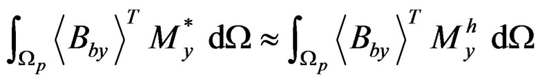
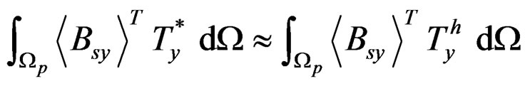
As an example, in recovering , substituting Equation (2) to Equation (10a) will produce:
 (11)
(11)
Using Gauss numerical integration, Equation (11) can be expressed as:
 (12)
(12)
with n is the number of element’s Gauss integration points which included in patch, J is Jacobian matrix and ω is weighting factor.
Equation (12) can also be expressed as
 (13)
(13)
Where
 and
and  (14)
(14)
with m is number of elements in a patch, and
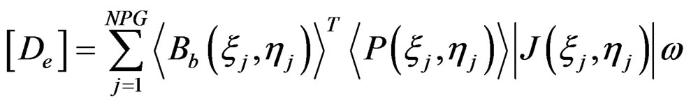 (15)
(15)
 (16)
(16)
with NPG is number of Gauss points in each element in a patch, and n = m × NPG. Then, using least square fit method, we define the following function
 (17)
(17)
And minimizing it to , yields
 (18)
(18)
In some patch configuration, [D] is probably unstable. This problem can be solved by defining function
 (19)
(19)
Minimizing that equation to {an} will produce:
 (20)
(20)
or
 (21)
(21)
with
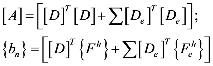 ; (22)
In above,  and
and  have the same expression as
  and
and , but the integrals are applied on each element.
2.4. Error Indicator and Refinement
Error estimation will become actual error if element size is set to be very small so as to approach zero, which creates infinite number of elements. Since calculation will never stop if element size is close to zero, we need an effective condition as criteria to terminate discrete process.
Indicator for exact error of a structure is defined by exact error of energy norm that is normalized by exact strain energy norm:
 (23)
(23)
where  is error in energy norm from this equation
 (24)
(24)
 = total exact error in energy norm and m = number of element in structure while
  is twice as much as exact strain energy of the whole structure, which for plate structure consists of bending and shear energy.
The above indicator can be computed only if exact solution is available which can be estimated by recovering the solution as discussed before.
Indicator for relative error f* of a structure with recovery method is:
 (25)
(25)
Value of  is obtained from:
 ;
; (26)
(26)
Error indicator represents value used as criteria to terminate the refinement process. This can be done by setting a condition for , that is whenever
  then the refinement process will stop. Generally, the value of
  is taken to be 5%. The permitted error indicator for structure is determined by:
 (27)
(27)
where  is permitted error of global energy norm, given by:
 (28)
(28)
In an optimal element mesh, distribution of error of energy norm is uniform in all elements, thus:
 (29)
(29)
where: m = number of element.
And then, we have:
 (30)
(30)
Thereby we can set a condition that error in every element i must be equal to or less than:
 (31)
(31)
where:  = permitted error of energy norm estimated for each element i.
Element whose error exceeds the permitted value most probably will be refined. Let us set a ratio:

An element must be refined if: 
3. Numerical Study
The following notation is used in the numerical study.
REP1: REP method, element based patch, minimum 3 elements in one patch.
REP2: REP method, element based patch, minimum 5 elements in one patch.
REP3, REP: REP method, element based patch, minimum 7 elements in one patch.
SPR1: SPR method, nodal based patch.
SPR2: SPR method, element based patch.
NELT: number of elements.
A study is held subjected to circular plate under uniform load (Figure 3). The study implements REP methods and covers various patch configurations as classified above. The result shows that all patch configuration give accurate result and close to other recovery methods for moment recovery.
However, external patch usage, happened if we allow minimum 3 or 5 elements in one patch (REP1 and REP2), may produce inaccurate result for shear force (Figure 4). Meanwhile, using only internal patches, which have minimum 7 elements in one patch, gives better result for shear force.
Figure 4 shows that external patches produce very large different results for shear force in the center of the plate. Approaching plate edge/support, the difference between REP1, REP2 and REP3 becomes smaller, but the result differs quite significant compared to other method’s result. It is widely known that bending plate element like DKMQ is developed with an aim to solve shear locking problem, hence, shear force accuracy is not considered important (Figure 5 and Figure 6).
The circular plate study is also analyzed for various plate thickness, including thin and thick plates, with R/h varied from 50, 5, and 2. The study shows similar accuracy characteristic for all R/h (Figure 7 and Figure 8). External patches usage for all R/h values produces inaccurate result for shear force in plate center.

Figure 3. Circular plate under uniform load.

Figure 4. Shear force distribution, circular plate, R/h = 50.

Figure 5. Mr moment distribution, circular plate, R/h = 50.

Figure 6. Mθ moment distribution, circular plate, R/h = 50.

Figure 7. Shear force distribution, circular plate, R/h = 5.

Figure 8. Shear force distribution, circular plate, R/h = 2.
In this numerical study, relative error indicator is studied for various element numbers, i.e. 3, 12, 27, and 48 elements. For thin plate (R/h = 50), all patch configuration including external patch give close relative error indicator result compared to SPR method result (Figure 9). However, for thicker plate with R/h equal 5 and 2 (Figure 10 and Figure 11), only full internal patch usage (REP3) gives very close result compared to SPR, while other patch configurations give fluctuant result. Based on this result, it can be concluded that only full internal patch usage is reliable and hence, for other study, only this patch configuration will be applied for REP method.
Another way to obtain good relative error indicator result is to consider only bending error indicator partially. Partial relative error indicator for bending gives no fluctuant result (Figures 12-14).
The next numerical study is held on fixed supported rectangular plate under uniform load (Figure 15). Uniform mesh refinement is used with 2 × 2, 4 × 4, 8 × 8 and 16 × 16 meshing. Moment recovery is studied at the plate center and at the support. The study shows that REP method gives super convergent result (Figures 16-18).
At plate center, 2 × 2 mesh of REP method gives quite high error percentage, but the result converges rapidly which is less than tolerance limit 5% for only 4 × 4 mesh.

Figure 9. Total relative error indicator, circular plate, R/h = 50.

Figure 10. Total relative error indicator, circular plate, R/h = 5.

Figure 11. Total relative error indicator, circular plate, R/h = 2.

Figure 12. Partial relative error indicator for bending, circular plate, R/h = 50.

Figure 13. Partial relative error indicator for bending, circular plate, R/h = 5.

Figure 14. Partial relative error indicator for bending, circular plate, R/h = 2.

Figure 15. Rectangular plate under uniform load.

Figure 16. Error percentage of flexural moment, center of fixed supported rectangular plate, uniform load.

Figure 17. Error percentage of flexural moment, support of fixed supported rectangular plate, uniform load.

Figure 18. Relative error indicator, fixed supported rectangular plate, uniform load.
With the same meshing, SPR1 (nodal based patch) has reached that tolerance limit, but SPR2 (element based patch), projection method and averaging method give higher value than tolerance limit.
At plate support, 4 × 4 mesh of REP method still gives much high error percentage (24.5%), but 16 × 16 mesh gives almost exact solution (0.01%) which is much better compared to SPR and averaging method. In this case, projection method gives very poor result compared to others.
Total relative error indicator produced by REP method shows close result to SPR1, SPR2, and averaging method, while projection method gives poorer result.
Circular plate as shown in Figure 19 is also studied for both uniform and adaptive mesh refinement. The uniforrn mesh refinement scheme is shown in Figure 20 and the adaptive mesh refinement is shown in Figure 21. It has been shown that adaptive mesh refinement gives better result than uniform one. For both refinements, for either fixed nor simply supported circular plate, REP method gives super convergent result, close to SPR result (Figures 22 and 23 for uniform mesh refinement and Figures 24 and 25 for adaptive mesh refinement). REP’s total error indicator for both refinements and both support types are closed to those of SPR1, SPR2 and averaging method, which are much better than that of projection method.
4. Conclusions
Patch type usage is sensitive in REP application. External patches usage gives fluctuant result in shear force recovery in REP application, hence, only internal patches are recommended. External patch usage still gives similar REP relative error indicator for thin plate, but gives higher relative error indicator for thick plate. Full internal patch usage does not give significant REP relative error indicator difference for both thin and thick plates.
Partial relative error indicator for bending gives good result without any fluctuant result for various element numbers.

Figure 19. ¼ of circular plate under uniform load.

Figure 20. Uniform mesh refinement scheme for circular plate.

Figure 21. Adaptive mesh refinement scheme for circular plate.

Figure 22. Relative error indicator, fixed supported circular plate, uniform mesh refinement.

Figure 23. Relative error indicator, simply supported circular plate, uniform mesh refinement.

Figure 24. Relative error indicator, fixed supported circular plate, adaptive mesh refinement.

Figure 25. Relative error indicator, simply supported circular plate, adaptive mesh refinement.
REP method gives very close result compared to SPR method. Generally, both REP and SPR give better result than averaging and projection method.
5. Acknowledgements
The writer would like to thank to the Indonesian Ministry of National Education, Directorate General of Higher Education (MNE-DGHE) and French Embassy in Jakarta for the research grant given to the writer in the project of International Joint Research between Universitas Indonesia (UI), Indonesia and Université de La Rochelle (ULR), France.
REFERENCES
- O. C. Zienkiewicz and J. Z. Zhu, “The Superconvergence Patch Recovery and a Posteriori Error Estimation in the Finite Element Method, Part 1: The Recovery Technique,” International Journal for Numerical Methods in Engineering, Vol. 33, No. 7, 1992, pp. 1331-1364. doi:10.1002/nme.1620330702
- O. C. Zienkiewicz and J. Z. Zhu, “The Superconvergence Patch Recovery and a Posteriori Error Estimation in the Finite Element Method, Part 2: Error estimates and adaptivity,” International Journal for Numerical Methods in Engineering, Vol. 33, No. 7, 1992, pp. 1364-1382. doi:10.1002/nme.1620330703
- Z. Z. Zhang, “Ultraconvergence of the Patch Recovery Technique,” Mathematics of Computations, Vol. 65, No. 216, 1996, pp. 1431-1437. doi:10.1090/S0025-5718-96-00782-X
- B. Boroomand and O. C. Zienkiewicz, “Recovery by Equilibrium in Patches (REP),” International Journal for Numerical Methods in Engineering, Vol. 40, No. 1, 1997, pp. 137-164. doi:10.1002/(SICI)1097-0207(19970115)40:1<137::AID-NME57>3.0.CO;2-5
- B. Boroomand and O. C. Zienkiewicz, “An Improved REP Recovery and the Effectivity Robustness Test,” International Journal for Numerical Methods in Engineering, Vol. 40, No. 17, 1997, pp. 3247-3277. doi:10.1002/(SICI)1097-0207(19970915)40:17<3247::AID-NME211>3.0.CO;2-Z
- B. Boroomand, M. Ghaffarian and O. C. Zienkiewicz, “On Application of Two Superconvergent Recovery Procedures to Plate Problems,” International Journal for Numerical Methods in Engineering, Vol. 61, No. 10, 2004, pp. 1644-1673. doi:10.1002/nme.1128
- Z. Zhang and A. Naga, “Polynomial Preserving Gradient Recovery and A Posteriori Estimate for Bilinear Element on Irregular Quadrilaterals,” International Journal of Numerical Analysis and Modeling, Vol. 1, No. 1, 2004, pp. 1-24.
- O. C. Zienkiewicz and J. Z. Zhu, “The background of Error Estimation and adaptivity in Finite Element Computations,” Computer Methods in Applied Mechanics and Engineering, Vol. 195, No. 4-6, 2006, pp. 207-213. doi:10.1016/j.cma.2004.07.053
- A. Duster, et al., “pq-Adaptive Solid Finite Elements for Three-Dimensional Plates and shells,” Computer Methods in Applied Mechanics and Engineering, Vol. 197, No. 1-4, 2007, pp. 243-254. doi:10.1016/j.cma.2007.07.020
- Ph. Destuynder, et al., “Adaptive Mesh Refinements for Thin Shells Whose Middle Surface Is Not Exactly Known,” Computer Methods in Applied Mechanics and Engineering, Vol. 197, No. 51-52, 2008, pp. 4789-4811. doi:10.1016/j.cma.2008.07.001
- M. Ainsworth, et al., “A framework for Obtaining Guaranteed Error Bounds for Finite Element Approximations,” Journal of Computational and Applied Mathematics, Vol. 234, No. 9, 2010, pp. 2618-2632. doi:10.1016/j.cam.2010.01.037
- J. H. Nie, et al., “Development of an Object-Oriented Finite Element Program with Adaptive Mesh Refinement for Multi-Physics Applications,” Advances in Engineering Software, Vol. 41, No. 4, 2010, pp. 569-579. doi:10.1016/j.advengsoft.2009.11.004
- V. S. Lukin, et al., “A Priori Mesh Quality Metric Error Analysis Applied to a High-Order Finite Element Method,” Journal of Computational Physics, Vol. 230, No. 14, 2011, pp. 5564-5586. doi:10.1016/j.jcp.2011.03.036
- K. J. Bathe, et al., “The use of Nodal Point Forces to Improve Element Stresses,” Computers and Structures, Vol. 89, No. 5-6, 2011, pp. 485-495. doi:10.1016/j.compstruc.2010.12.002
- I. Katili, et al., “A New Discrete Kirchoff-Mindlin Element Based on Mindlin-Reissner Plate Theory an Assumed Shear Strain Fields. Part 2: An extended DKQ element for Thick-Plate Bending Analysis,” International Journal for Numerical Methods in Engineering, Vol. 36, No. 11, 1993, pp. 1885-1908. doi:10.1002/nme.1620361107
- J. E. Akin, “Finite Element Analysis with error estimators,” Elsevier Butterworth-Heinemann, Burlinton, 2005.