World Journal of Nuclear Science and Technology
Vol.2 No.3(2012), Article ID:21248,3 pages DOI:10.4236/wjnst.2012.23014
Gearbox Scheme in High Temperature Reactor Helium Gas Turbine System
1Qinghuangdao School, North East Petroleum University, Qinghuangdao, China
2Institute of Nuclear and New Energy Technology, Tsinghua University, Beijing, China
Email: 36190@qq.com, xuanyu@tsinghua.edu.cn
Received January 2, 2012; revised February 17, 2012; accepted March 15, 2012
Keywords: High Temperature Gas Cooled Reactor; Gear Box; Planetary Gear
ABSTRACT
Helium Turbine is used in High Temperature Reactor Helium Gas Turbine (HTR-GT) system, by which the direct helium circulation between the reactor and turbine generator system will come true. Between helium turbine and generator, there is gearbox device which reduces the turbine rotation speed to normal speed required by the generator. Three optional gearbox schemes are discussed. The first is single reduction cylindrical gearbox, which consists of one high speed gear and one low speed gear. Its advantage is simple structure, easy to manufacture, and high reliability, while its disadvantage is large volume and misalignment of input and output axle. The second is planetary gear mechanism with static planet carrier. The third is planetary gear mechanism with static internal gear. The latter two gearbox devices have similar structure. Their advantage is small volume and high reduction gear ratio, while disadvantage are complicated structure, many gears, low reliability and low mechanical efficiency.
1. Introduction
The 10 MW High Temperature Gas-cooled Test Reactor (HTR-10) has been built and come critical in 2000. HTR- 10 still uses steam generator to transfer decay energy to electric power generator [1,2]. In detail, the coolant helium in primary circuit flows to evaporator, in which water vapor is produced and decay energy is transferred from helium to water vapor. The hot water vapor flows to turbine which drives the electric generator to generate power. High Temperature Reactor Helium Gas Turbine (HTR-GT) system, which will be developed based on HTR-10, will use coolant helium to drive the turbine directly, without intermediate heat transfer circuit. The project will simplify the whole energy converse system and increase the heat efficiency [3].
The thermal circuit for HTR-GT is shown in Figure 1. Helium with high pressure, heated in the nuclear reactor core, flows from the reactor to the turbine and drives it. The turbine drives the electric generator and compressors simultaneously. The off-gas from the turbine is still hot and will flow through recuperator, where heat is transferred to helium at high pressure side. Then the off-gas flows through precooler and the temperature is reduced lower. Helium, with low pressure and low temperature, flows through compressor group including inter cooler and is compressed to high pressure. High pressure helium
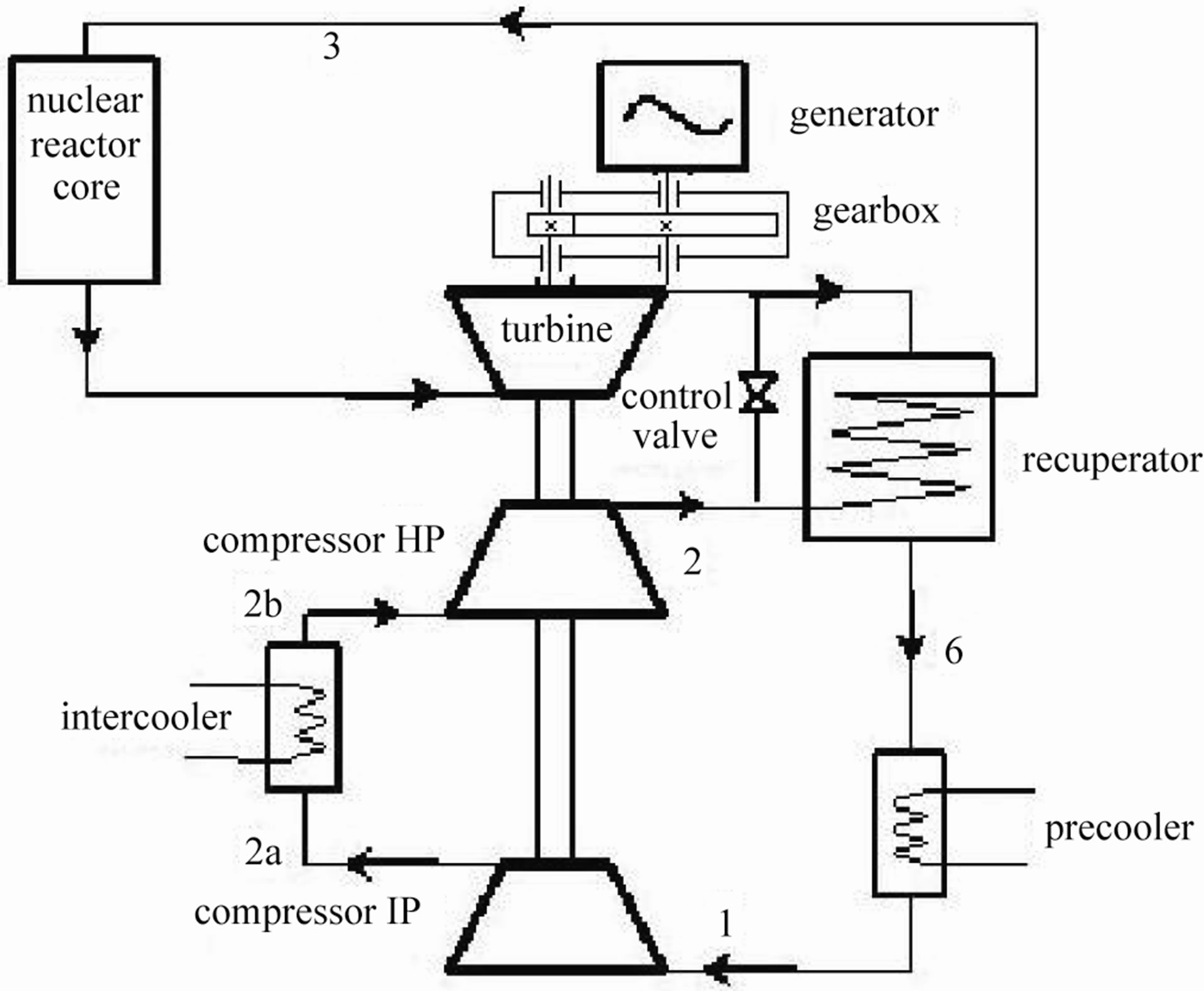
Figure 1. Thermal circuit of Helium turbine power generation system.
flows through recuperator at the high pressure side and is preheated. Finally the preheated high pressure helium flows to the reactor core and is heated again.
From Figure 1, it can be seen there is a gearbox between turbine and generator. In Power Conversion Unit (PCU), Turbine and generator are integrated vertical layout system. From bottom to top, there are low pressure compressor, high pressure compressor, turbine, joint coupler 1, gear box (including gear box module, flexible joint coupler 2 and thrust bearing module), and generator. The real position of gearbox in PCU is shown in Figure 2.
The function of gear box is transferring the rotation energy of helium turbine to rotor of generator, reducing rotation speed to normal electric network frequency, and supporting the rotor of generator. The rotation speed of helium turbine is 15,000 rpm, and 3000 rpm for generator.
The transfer power of gearbox is 2500 kW. The normal input speed is 15,000 rpm, while highest input speed is 18,000 rpm. The normal output speed is 3000 rpm, while highest output speed is 3600 rpm. The mechanical efficiency is 98%. The leakage ratio for lubricant is <5 g/day. The working atmosphere is helium. The pressure in gearbox is 0.7 MPa, while temperature is 65˚C.
The differences between this gearbox and other normal industrial gear box are high rotation speed, high power transfer, and vertical layout. Most of gearboxes are installed horizontally, that is the axle of gear box is parallel to ground. The gearbox in HTR-GT is installed vertically, that is the axle of gear box is perpendicular to ground.
2. Single Reduction Cylindrical Gearbox
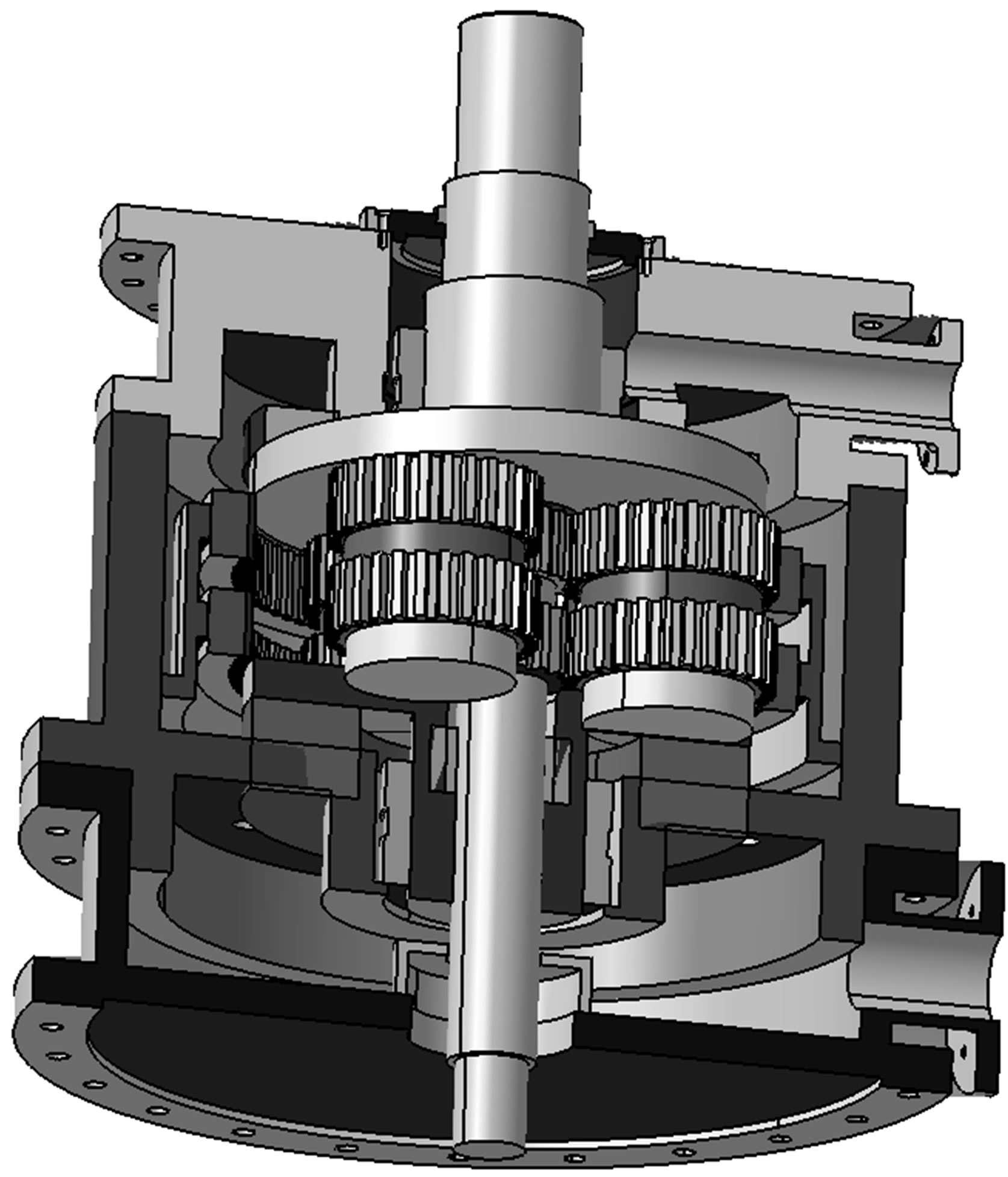
The main parts of single reduction cylindrical gearbox are a pair of meshing gears. The input side of high speed gear is connected to the output axle of helium turbine by flexible joint coupler. The high speed gear has small diameter, while low speed gear has large diameter. These two gears are installed side by side vertically. As the power is relatively high, the designed width of two gears is large. To ensure the length of action, there is not tooth in central part. The mate tooth becomes two parts, upper and lower. The 3 dimensional modal is shown in Figure 3. The 2 dimensional design drawing is shown in Figure 4" target="_self"> Figure 4.
Figure 2. Gearbox device in power conversion unit.
Because the rotation speed is very high, the meshing parts of the two gears are lubricated by oil injection. Special oil supply line and nozzle are installed for direct oil injection on the gears. At the bottom of the gearbox, special oil return line is installed for collecting oil back to the oil station. The oil is filtered and cooled in the special oil station.
At the bottom internal side of gearbox, there is a shoe plate, by which both high speed gear and low speed gear are supported. On the contrary, the upper parts of these two gears are supported directly on gearbox case. There

Figure 3. Meshed gear part of single reduction cylindrical gearbox.
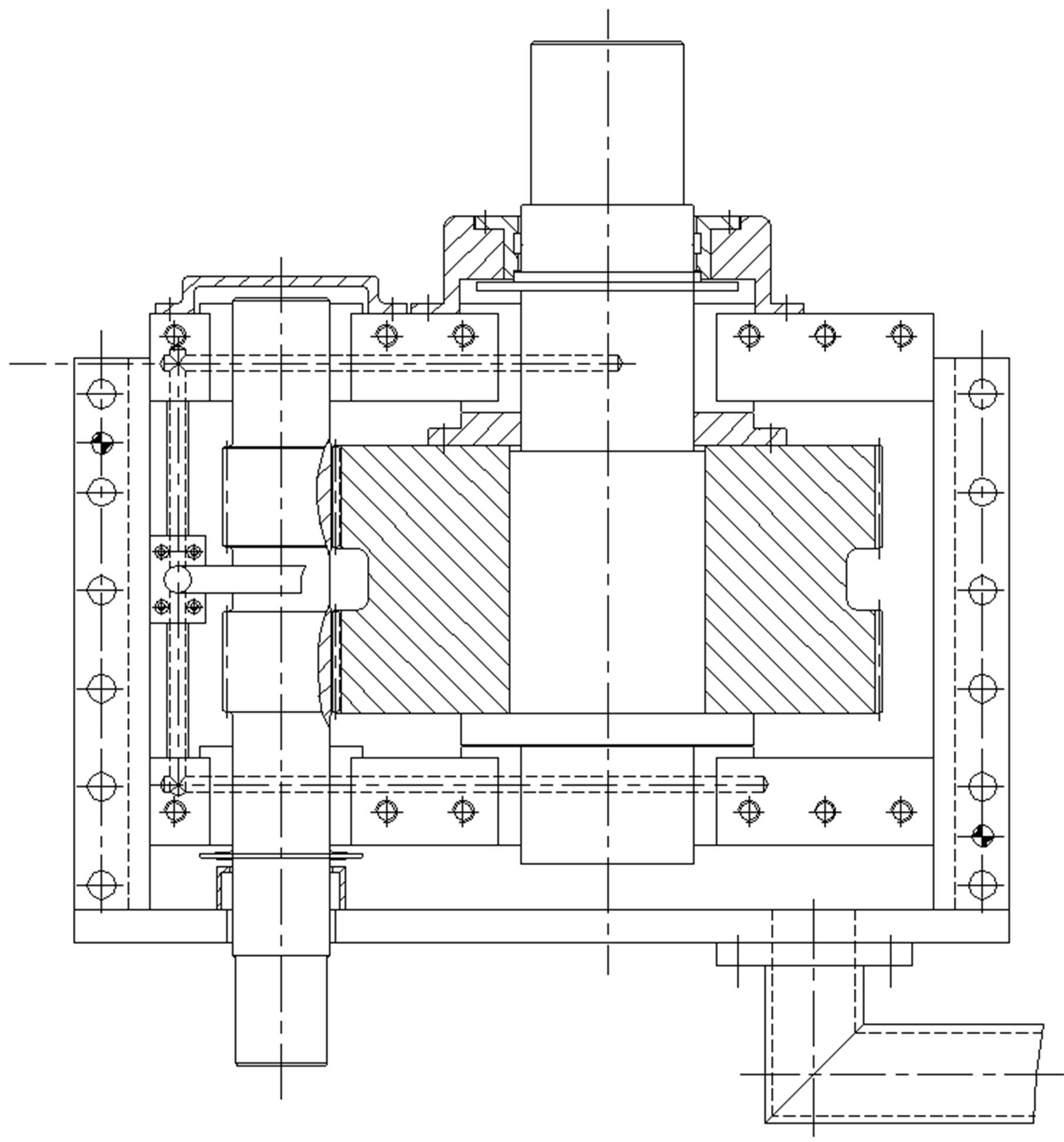
Figure 4. Assembly diagram of single reduction straight gearbox.
are high speed bearings on both ends of the high speed gear. For low speed gear, there are thrust bearings on both ends, which bear the axial force and the weight of low speed gear.
Both high speed gear and low speed gear are skew gear, with upper gear tooth skew opposite to the lower gear tooth. With this kind of skew direction, the axial force of two meshing parts is counteracted.
The whole gearbox case is divided into 2 parts, which are connected by bolts. The contacting area is sealed by special material to prevent lubricant leakage.
3. Planetary Gear Mechanism with Static Planet Carrier
For the planetary gear mechanism with static planet carrier, it is not the real planetary gear train but ordinary gear train in concept because all the gear axles are fixed. Planetary gear mechanism with static planet carrier can be divided into double-geared drive. Because there are 3 planetary gears, the gear mechanism includes 3 doublegeared drives which deliver the power together.
The structure of planetary gear mechanism with static planet carrier is shown in Figure 5. The whole gearbox case is cylinder which is divided into 2 parts, the upper and lower. There is intermediate shoe plate between these two part cases. All 3 parts, intermediate shoe plate, upper gearbox case and lower gearbox case, are connected together by bolts. The contacted area is also sealed by special sealing material to prevent lubricant leakage. There is shoe plate under the gear box by which whole gear box is fixed in the power conversion unit (PCU).

Figure 5. 3-dimension schematic sketch of planetary gear mechanism with static planet carrier.
To prevent the lubricant leakage from the bottom of high speed gear, a special seal device is installed. There is a shoe pallet, with center part a through hole, under the intermediate shoe plate. The input high speed axle cross the central hole and connected with high speed sun wheel. A pair of high speed rolling bearings is also installed in the central hole to support the high speed axle.
Three axles of planetary gears are equally distributed and all the axles are fixed on static planet carrier. The static planet carrier is connected together with intermediate shoe plate. Three planetary gears mesh with high speed sun wheel on one side, while meshing annular wheel on the other side. The annual wheel rotates and drives output axle rotating together.
4. Planetary Gear Mechanism with Static Internal Gear
Planetary gear mechanism with static internal gear is real planetary gear. The planet carrier rotates, while the annual wheel is fixed. This kind of gear mechanism has relatively high speed reduction rate.
The structure of planetary gear mechanism is shown in Figure 6. The gearbox case is also cylinder, divided into 3 parts, upper, intermediate, and lower and connected by bolts. The contacting area is sealed by special material. The input oil line is installed on the upper case, while the output oil line is installed on the lower case. There is a horizontal back plate, supporting the whole planetary gear mechanism, under the lower surface of intermediate gearbox case. There is also a through hole in the horizontal back plate in which the high speed axle crosses. To support the high speed axle, a high speed bearing is installed in the through hole, too. The planet carrier, at the outer side of the high speed axle, is partially installed in the through hole in the horizontal back plate. The outer ring of high speed bearing contacts with the hole of planet carrier. Between the planet carrier and the through hole in the horizontal back plate, another rolling bearing is installed to support the carrier.
The carrier supports 3 evenly distributed planetary wheels. The inner side of 3 planetary wheels meshes with high speed gear, while outer side meshing with annular wheel. The annular wheel is fixed on the horizontal back plate. The carrier is connected with the lower speed output axle which makes them rotating simultaneously.
There is also a through hole on the center of upper gearbox case. The upper end of high speed axle is installed in this through hole, supported by a rolling bearing. To secure enough meshing length, the teeth of the high speed gear, planetary gear and annular gear are all divided into two parts, with intermediate blank.
5. Comparisons of 3 Gearbox Schemes
Single reduction cylindrical gearbox consists one high
 (a)
(a) (b)
(b)
Figure 6. Planetary gear mechanism with static internal gear, (a) 3-dimension schematic sketch; (b) 2-dimension assembly diagram.
speed gear and one low speed gear. The advantage of this kind of gearbox is simple structure, easy manufactured, high reliability because of only two gears. The power lose is lower because the motion transfers between only two gears, which makes single reduction cylindrical gearbox higher efficiency. Because of relatively high reduction ratio, 5, the pith circle diameters of two gear different greats. The diameter of low speed gear is very large which leads to big volume of the gear box. As two axles lay parallel, the input and output axles are not concentricity.
There are similar structures for planetary gear mechanism with static planet carrier and planetary gear mechanism with static internal gear. As their speed reduction ratio can be very high, the volume and weight are small and the structure is compact. The supporter for gearbox in PCU can also be designed easily. The disadvantages of these two kinds of gearbox are more complicated structure, more gears and lower reliability. Any meshing teeth on 5 gears fails, the reactor should be stopped and the gearbox should be repaired or replaced. The maintenance for components in PCU is not an easy task. More gears in motion transfer lead to higher power loss and lower efficiency. Another problem of power loss is that the lost power is converted into heat. This heat increases the temperature of gearbox and lubricant and thus increases the temperature of PCU. The requirement for cooling system of PCU and lubricant would be stricter.
In summary, for 3 gearbox schemes, each has its strong point. The authors prefer to single reduction cylindrical gearbox. One main point of nuclear power plant is high reliability. Designer should try to increase the reliability of nuclear power plant in any kind of possible way. The loss is also very high for each shut-down. To increase the reliability of PCU, single reduction cylindrical gearbox should be used because of fewer gears. Although planetary gear mechanism is small and easy to install, it should be avoided because of its more gears default.
Finally, gearbox scheme in helium turbine system is successful, avoiding the high speed electric generator and high power transducer to reduce the speed. The manufacture fee of PCU is reduced. The shortage of this scheme is the introduction of lubricant subsystem into PCU.
REFERENCES
- Z. X. Wu, D. Lin and D. Zhong, “The Design Features of the HTR-10,” Nuclear Engineering and Design, Vol. 218, No. 1-3, 2002, pp. 25-32. doi:10.1016/S0029-5493(02)00182-6
- Z. Y. Zhang and S. Y. Yu, “Future HTGR Developments in China after the Criticality of the HTR-10,” Nuclear Engineering and Design, Vol. 218, No. 1-3, 2002, pp. 249-257. doi:10.1016/S0029-5493(02)00204-2
- Y. L. Sun, Z. K. Zhang and Y. G. Zhang, “Preliminary Study on the HTR-10 Gas Turbine Cycle Design,” High Technology Letters, Vol. 11, No. 7, 2001, pp. 99-102.