Optics and Photonics Journal, 2012, 2, 294-299
http://dx.doi.org/10.4236/opj.2012.24036 Published Online December 2012 (http://www.SciRP.org/journal/opj)
Controlling the Flow of Microscopic Particles—The
Role of Beam Size
Jitendra Bhatt1*, Ashok Kumar2, Saiyed Nisar Ali Jaaffrey1, Ravindra Pratap Singh2
1Department of Physics, University College of Science, Mohan Lal Sukhadia University, Udaipur, India
2Theoretical Physics Division, Physical Research Laboratory, Ahmedabad, India
Email:*jitendrabhattprl@gmail.com
Received September 16, 2012; revised October 15, 2012; accepted October 28, 2012
ABSTRACT
Flow of micro particles and fluids is important in many microscopic systems. Here we present details of our finding of a
directional flow of micro particles due to a single beam optical trap. It was found that the directional flow depends upon
the size of optical trap, the number density of particles in the solution and the time after the trap was created. We sug-
gest controlling the motion of microscopic particles in a fluid by varying a simple parameter like beam size for micro-
fluidics applications.
Keywords: Optical Manipulation; Optical Tweezers; Directional Flow
1. Introduction
Since the pioneering work done by Ashkin [1] on single
beam gradient trap sometimes referred to as optical
tweezers, optical trapping has found diverse applications
in biophysical and colloidal studies as a tool for micro-
manipulation [2-7]. In most of the applications, micro-
scopic objects like particles, colloids or biological cells
moving around in a fluid are forced to remain confined
in the trap volume. However, instead of restricting the
movement, the optical trapping can also be used to fa-
cilitate the desired movement of the microscopic objects.
In 1980s when researchers were still struggling for a 3D
trap, Buican et al. [8] used properties of a 2D optical trap
for transporting microspheres and biological cells to mil-
limeter distances. Their automated optical manipulator
used two orthogonal laser beams—propulsion beam and
deflection beam for this purpose while a third beam was
used as a probe beam to discriminate cells to be deflected.
In their experiment the cells moved along with the beam
trapped in two dimensions. In late 1980s invention of 3D
optical traps popularly known as optical tweezers caught
the fancy of biologists and the work shifted towards
trapping and manipulating single biological cells. Here
we point out our observations, which we believe are sig-
nificant one, the role of a 2D trap in an inverted micro-
scope configuration. In our experiment we have obtained
a controlled flow of micro-particles and fluids using an
optical trap. We have found that the trap is able to attract
particles from substantially large distances, the distances
being orders of magnitude more than the diameter of the
beam or the particle itself. One can easily see that the
directional movement in our experiment is very much
different from the transportation achieved by Buican et al.
[8]. Although light intensity of the trap has been used to
control the flow of particles earlier [9], these methods
relied on well established technique for optical trapping
and used overfilling of the objective lens for their purpose.
The present experiment provides extra handle in the
form of beam size to control the movement of micro-
scopic particles in a standard 3D optical trap configura-
tion that uses inverted microscope. However, it is very
important that before making the observations, one takes
care of certain practical considerations associated with
the set up [2,10].
2. Experimental Setup
Our experimental setup shown in Figure 1, is typical of
an inverted optical microscope based optical tweezers
setup. It consists of a diode laser (785 nm, maximum
power 46 mW) and inverted microscope from Nikon
(TE-2000 U). The size of the beam entering the back
aperture of the objective lens is 0.18 mm. It is a diverg-
ing beam with divergence of 0.02 radians at the back
aperture of the objective lens. The laser beam is directed
to the oil-immersion high numerical aperture (NA 1.40)
100X objective lens (Plan Apo vc 100X/1.40 oil, Nikon)
using periscopic mirrors (M1, M2) and the dichroic mir-
ror (DM). The refractive index of the immersion oil is
1.515. The particles used in this experiment are 0.99 µm
*Corresponding author.
C
opyright © 2012 SciRes. OPJ
J. BHATT ET AL. 295
Figure 1. Experimental set up for directional flow of micro-
scopic particles.
polystyrene latex beads (from Bang’s Laboratory). These
particles are spherical in shape and they were suspended
in double distilled water. The specimen sample was illu-
minated by a halogen lamp assembly. The light from
illuminated particles was sent to the cooled color CCD
camera (Evolution VF, Q-Imaging) through the objective
lens, dichroic mirror (DM) and a beam steering prism (P).
The halogen lamp is used to illuminate the sample. The
same objective lens is used for viewing and trapping of
the particles. A color glass filter (F) is used before the
CCD camera to block the laser for avoiding saturation of
the camera. The stage movement with a knob was used to
bring the trap at the different parts of the sample. Unlike
the most optical trapping experiments which use a beam
expanding device to fill the back aperture of the objective
lens by the trapping beam, we do not use any beam ex-
panding device.
3. Theoretical Background
Most of the theoretical work on optical tweezing or trap-
ping of particles that involves calculation of optical gra-
dient forces is applicable to either small particles (parti-
cle size wavelength λ) or very large particles R

R
[11,12]. The estimation of force for small par-
ticles requires electromagnetic (EM) theory where the
EM field is computed by plane wave Fourier decomposi-
tion of the focused beam which is used to calculate the
Maxwell stress tensor to find out the force on the parti-
cle. For very large particles the EM theory can be re-
duced to geometrical ray optics approximation and the
force is calculated by vector summation of the contribu-
tions of single rays which are reflected and refracted by
the particle. For R
, the EM approach reduces to a
dipole approximation where the particle interacts with
the field only as an electric dipole. However, for com-
puting the force on a particle with size comparable to the
wavelength, one needs to sum over the plane wave Fou-
rier components for the entire volume of the particle.
This makes the calculations very difficult. Moreover, due
to interference effects between the plane waves, the cal-
culated forces are found to be weaker than the experi-
mental results [2]. To solve this problem, Tlusty, Meller
and Bar-Ziv (TMB) [13] adapted a new approach for
calculating the interaction of the dielectric particle with
the focused beam of light. Instead of decomposing the
fields into Fourier components they used the property of
strong localization of the fields that makes the phase
variation of the EM fields appreciably small over the
diffraction limited spot of the beam. Therefore, the main
contribution to the interaction arises from the steep varia-
tions in the amplitude of the fields and not from the in-
terference effects. Thus, the relevant length scale for in-
teraction becomes the spot size w and not R that makes
this approach [13] applicable to particles of any size. In
our experiment, the particle size R being comparable to
the wavelength λ, and the experimental results depending
on the beam spot, we find the TMB approach most suit-
able for our purpose of calculating the force on the parti-
cle. Since the interaction depends on the amplitude of the
field only, one can deal with the observable quantity that
is intensity of the light. In case of a diode laser, on fo-
cusing a laser beam through an objective lens, the spot
formed is not exactly spherical; rather it is an ellipsoidal
with the eccentricity ε. Considering the trap volume to
have an axial symmetry, the localized electromagnetic
fields near the focal point can be given by [13].

22
0222
,exp
22
rz
Irz Iww



(1)
where 0
I
is the energy density at the center of the trap,
and w w
are the dimensions of the beam waist in
transverse and axial dimensions respectively. The frame
of reference is defined by the geometrical focus of the
beam, 0rz
. It is known that the optical trap formed
by focusing of a laser beam through an objective lens is
of the form of an Airy disc (first bright disc of the Airy
pattern formed). Under Gaussian approximation its size
w can be given by
0.42
f
wD
(2)
where λ is the wavelength of the light, ƒ is the focal
length of the lens, and D is diameter of the beam being
focused.
The TMB approach makes the calculation of the force
quite simple, knowing the intensity one can calculate the
dipole interaction energy by a simple integral and taking
the gradient of the dipole energy provides with the rele-
vant central restoring force of the trap [13].
Copyright © 2012 SciRes. OPJ
J. BHATT ET AL.
Copyright © 2012 SciRes. OPJ
296
 


2
12
2
0esinh
u
c
rIwA a

u
(3)
The anisotropy factors are embedded in the term

A



2
12
4πesinh
22
c
a
cc
c
bb
A
erferfa u

 
 
 .
In Equation (3), 0p1

 is the relative differ-
ence of the dielectric constants of particle
p
and the
surrounding medium 0
. The radius of the particle
being trapped is normalized as
R
Rw
, while the dis-
tance of the particle from the trap centre r is the normal-
ized to urw and

13
π6
cc
Rwab .
Based on Equation (3) the central restoring forces have
been plotted in Figure 2. The variation of central restor-
ing force for trap size 0.96 µm has been shown in Figure
2(a) and for trap size 0.45 µm in Figure 2(b).
These graphs convincingly suggest that for large trap
sizes the range of trapping force is large while for small
trap sizes the range is small.
4. Results and Discussion
In our experiment, the size of the beam before entering
the back aperture of the objective lens is 0.67 mm. The
focal length of the objective lens is 2 mm that gives the
spot size of the focused trapping beam as 0.99 µm; how-
ever, the experimentally measured spot size of the trap
has come out to be 0.96 µm.
Figure 2 shows the variation of central restoring force
with distance calculated from Equation (3). The restoring
force for the particle size R = 0.99 µm and the trap size w
= 0.96 µm are shown in Figure 2(a), while Figure 2(b)
shows the same for a reduced trap size of w = 0.45 µm. It
becomes clear from these graphs that when the trap size
is large, the range of force is large, thus the trap attracts
the particles even from the large distances. While for
small trap size, the value of maximum force is large but
the range of the force is reduced, and the trap cannot at-
tract particles from the large distances.
In our experiment, we observed that for the trap size
0.96 µm, obtained with a beam without any lens before
the objective, there was a directional flow of particles
from all parts of the sample towards the trap position.
This flow was found to be dependent on the number den-
sity of the particles; it was observed that below a certain
number density (~2 × 10⁸ particles/ml) no significant
directional flow could be observed. It was also observed
that even for sufficient number density of particles, the
establishment of directional flow takes some time to be-
gin. It was found that the particles were coming to the
trap and moving out of it. This phenomenon can be seen
in the frames captured by the CCD camera (Figure 3).
For the smaller trap size (0.45 µm), which could be
achieved through filling the back aperture of the objec-
tive lens, no significant directional flow of particles
could be observed, but the particles could be trapped
stably at the trap position. It suggests that for larger trap
size the range of trapping force in the X-Y plane is large,
while the trap strength is low. However, for smaller trap
sizes the range of trapping force in the X-Y plane has
decreased although the trap strength has increased.
For calculating the velocity of particles under the in-
fluence of trapping force, we analyzed the frames cap-
tured with CCD camera. We obtained distances of dif-
ferent particles from the trap centre by measuring dis-
tances they moved between the two frames. We have
taken 48 frames with a time interval of 0.1 seconds be-
tween two consecutive frames (frame rate of the CCD is
10 fps). This information was used to calculate the aver-
age velocity of the particles and the force acting on them
at different distances from the trap centre. Following the
2
1
0
0 1 2 3 4 5
Distance from the trap centre in μm
Force in pN
4
3
2
1
0
Force in pN
0 1 2 3 4 5
Distance from the trap centre in μm
(a) (b)
Figure 2. Graphs showing theoretical variation (plot of Equation 3) of restoring trap force with distance from trap centre, (a)
Represents the variation for the trap size 0.96 µm; (b) Represents the variation for the trap size 0.45 µm. For theoretical cal-
culations we have taken αp = 2.5, α0 = 80.
J. BHATT ET AL. 297
(a) (b)
(c) (d)
Figure 3. Frames showing the directional motion of polystyrene particles towards the trap position. The trap position has
been shown by the circle towards which the arrows are pointing. The same numbers inside the circle represent the same par-
ticle at different positions. (a) and (b) show the movement of particle 1 in two successive frames; (c) and (d) show the move-
ment of particle 2 in two successive frames.
calculated plot for the force (Figure 4), it is clear that
with the distance from the trap, the average velocity first
increases, reaches to the maximum and then decreases.
As the particles approach the trap, they start hindering
the motion of each other because of collisions, which is
the reason for the average velocity to be maximum not at
very near to the trap but slightly far from it. The posi-
tioning accuracy of the particle is fundamentally limited
by the Brownian motion of the particle and the accuracy
of vision sensing [14]; this led to the precision of ±0.5
µm/sec in determination of the velocity.
The range of central restoring force of optical trap of
size 0.96 µm is about 4 µm; hence trap must attract parti-
cles from distances up to 4 µm only and bring them at the
trap centre. However, because of Brownian motion of
particles, another particle comes in the position of the
previous particle and consequently gets attracted towards
the trap. Such action sets the formation of a short lived
channel (where these particles have to face less visco-
sity) for easy flow of other particles. This phenomena of
channel formation draws similarity from the flow in-
duced channel formation under pressure gradient forces
[15]. Once the channels are formed, they lead to the at-
traction of particles towards the trap even from the dis-
tances several times the range of central restoring force
of the trap. The higher number density of particles helps
in the formation of these short lived channels, this leads
to easier observation of directional flow in higher particle
number density solutions. For smaller trap size (0.45 µm),
the range of the central restoring force is about 2 µm.
The smaller range of force results into attraction of less
number of particles towards the trap centre. It causes
decrease in formation of short lived channels and hence
less significant directional flow. As the formation of
short lived channels by movement of particles is impor-
tant in this directional flow, therefore, it takes time for a
Copyright © 2012 SciRes. OPJ
J. BHATT ET AL.
298
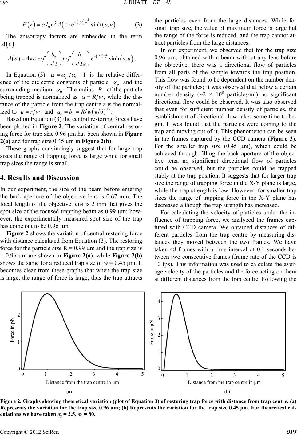
Figure 4. The experimental data showing variation of trap-
ping force on the particles with distance from the trap centre.
The size of the trap is 0.96 µm.
significant directional flow to take place since the trap is
switched on.
We observe that the theoretical approach which takes
spot size w as the relevant length scale of interaction and
valid for all the particle sizes [13], should have given the
correct range of forces to us. However, it is not very
successful in the present case, although it provides us a
qualitative explanation regarding range of forces for
bigger and smaller trap sizes. We can say that the gradi-
ent forces alone cannot describe this kind of directional
flow, one need to consider hydro-dynamical processes
involved in the system.
We know that the spherical aberrations [16-18] which
come into play because of refractive index mismatch in
the glass-water boundary decrease the stability of the
optical traps due to distorted focus. However, for a com-
parative study like ours, this does not affect the conclu-
sions, the aberrations being same throughout the experi-
ment.
5. Conclusion
In conclusion, we show an obvious but unexplored me-
thod to control the flow of particles that does not use
micro-channels and may allow the possibility of an en-
tirely fluidic process. Earlier studies used the light inten-
sity of the trap to control the flow of particles and used
the conventional method of overfilling the objective lens.
In contrast, we show that it’s not always required to
overfill the objective; instead one can use the original
beam and its different magnifications to control the flow
of microscopic particles.
REFERENCES
[1] A. Ashkin, J. M. Dziedzic, J. E. Bjorkholm and S. Chu,
trap for Dielectric Particles,” Optics Letters, Vol. 11, No.
5, 1986, pp. 288-290.
“Observation of a Single-Beam Gradient Force Optical
doi:10.1364/OL.11.000288
[2] K. Svoboda and S. M. Block, “Biological Applications of
Optical Forces,” Annual Review of Biophysics and Bio-
molecular Structure, Vol. 23, 1994, pp. 247-285.
doi:10.1146/annurev.bb.23.060194.001335
[3] K. Dholakia, G. Spalding and M. MacDonald, “Optical
Revolution in Optical Manipulation,”
Tweezers: The Next Generation,” Physics World, Vol. 15,
2002, pp. 31-35.
[4] D. G. Grier, “A
Nature, Vol. 424, No. 6950, 2003, pp. 810-816.
doi:10.1038/nature01935
[5] R. Dasgupta, S. K. Mohanty and P. K. Gupta, “Controlled
Rotation of Biological Microscopic Objects Using Opti-
cal Line Tweezers,” Biotechnology Letters, Vol. 25, No.
19, 2003, pp. 1625-1628. doi:10.1023/A:1025678320136
[6] C.-C. Huang, C.-F. Wang, D. S. Mehta and A. Chiou,
“Optical Tweezers as Sub-Pico-Newton Force Transduc-
ers,” Optics Communication, Vol. 195, No. 1-4, 2001, pp.
41-48. doi:10.1016/S0030-4018(01)01329-3
[7] V. Garbin, et al., “Changes in Microbubble Dynamics
ingle-Cell Manipula-
near a Boundary Revealed by Combined Optical Micro-
manipulation and High-Speed Imaging,” Applied Physics
Letters, Vol. 90, No. 11, 2007, p. 1.
[8] T. N. Buican, et al., “Automated S
tion and Sorting by Light Trapping,” Applied Optics, Vol.
26, No. 24, 1987, pp. 5311-5316.
doi:10.1364/AO.26.005311
[9] P. G. Schiro, C. L. Dubois and A. S. Kwok, “Large Cap-
ture-Range of a Single-Beam Gradient Optical Trap,”
Optics Express, Vol. 11, No. 25, 2003, pp. 3485-3489.
doi:10.1364/OE.11.003485
[10] K. C. Neuman and S. M. Block, “Optical Trapping,” Re-
view of Scientific Instruments, Vol. 75, No. 9, 2004, pp.
2787-2809. doi:10.1063/1.1785844
[11] M. Kerker, “The Scattering of Light and Other Electro-
magnetic Radiation,” Academic Press, New York, 1969.
[12] A. Ashkin, “Forces of a Single-Beam Gradient Laser Trap
on a Dielectric Sphere in the Ray Optics Regime,” Bio-
physical Journal, Vol. 61, No. 2, 1992, pp. 569-582.
doi:10.1016/S0006-3495(92)81860-X
[13] T. Tlusty, A. Meller and R. Bar-Ziv, “Optical Gradient
Forces of Strongly Localized Fields,” Physical Review
Letters, Vol. 81, No. 8, 1998, pp. 1738-1741.
doi:10.1103/PhysRevLett.81.1738
[14] C. Ropp, et al., “Manipulating Quantum Dots to Nano-
meter Precision by Control Of Flow,” Nano Letters, Vol.
10, No. 7, 2010, pp. 2525-2530. doi:10.1021/nl101105j
[15] R. D. Guy, T. Nagagaki and G. B. Wright, “Flow-Induced
ach and E. H. K. Stelzer, “Trapping Forces,
Channel Formation in the Cytoplasm of Motile Cells,”
Physical Review E, Vol. 84, No. 1, 2011, Article ID:
016310.
[16] A. Rohrb
Force Constants, and Potential Depths for Dielectric
Spheres in the Presence of Spherical Aberrations,” Ap-
plied Optics, Vol. 41, No. 13, 2002, pp. 2494-2507.
doi:10.1364/AO.41.002494
Copyright © 2012 SciRes. OPJ
J. BHATT ET AL.
Copyright © 2012 SciRes. OPJ
299
eng and D. [17] X. C. Yao, Z. L. Li, H. L. Guo, B. Y. ChZ.
Zhang, “Effects of Spherical Aberration on Optical Trap-
ping Forces for Rayleigh Particles,” Chinese Physics Let-
ters, Vol. 18, No. 3, 2001, pp. 432-434.
doi:10.1088/0256-307X/18/3/341
[18] E. Fallman and O. Axner, “Influence of a Glass-Water
Interface on the On-Axis Trapping of Micrometer-Sized
Spherical Objects by Optical Tweezers,” Applied Optics,
Vol. 42, No. 19, 2003, pp. 3915-3926.
doi:10.1364/AO.42.003915