Paper Menu >>
Journal Menu >>
 Journal of Minerals & Materials Characterization & Engineering, Vol. 9, No.3, pp.231-246, 2010 jmmce.org Printed in the USA. All rights reserved 231 Investigation on Two-Body Abrasive Wear Behavior of Silicon Carbide Filled Glass Fabric-Epoxy Composites N. Mohan*1, S. Natarajan1, S.P. KumareshBabu1, Siddaramaiah2 1Department of Metallurgical and Materials Engineering, National Institute of Technology, Tiruchirapplli- 620 015, India. 2Department of Polymer Science and Technology, Sri Jayachamarajendra College of Engineering, Mysore- 570 006, India. *Corresponding author: mohan_aitnit@yahoo.com ABSTRACT The effect of silicon carbide (SiC) particulate fillers incorporation on two-body abrasive wear behaviour of Glass Fabric - Epoxy (GE) composites was investigated and findings are analysed. The mechanical properties such as impact strength and surface hardness of the composites have also been reported. The wear behaviour of the composites were performed using pin-on-disc tester at varying abrasive distances viz., 25, 50, 75 and 100 m at a constant load of 10 N. The experiment was conducted using two different water proof silicon carbide (SiC) abrasive papers of 600 and 1000 grit size at a constant speed of 200 rpm under multi-pass condition. The wear loss of the composites was found increasing with the increase in abrading distances. A significant reductio n i n w e ar l os s and specific wear rates were noticed after incorporation of SiC filler into GE composite. This result indicates that the significant influence of SiC filler allowing less wear of matrix during abrasion which in turn facilitates lower fiber damage, due to the presence of SiC particles on the counter surface, which act as a transfer layer and effective barriers to prevent large-scale fragmentation. The worn surface features, were examined through scanning electron microscopy (SEM), in order to probe the wear mechanism. Key Words: Two-body abrasive wear, Glass-fabric, Epoxy-composites, Silicon carbide, Impact strength, Wear mechanisms. 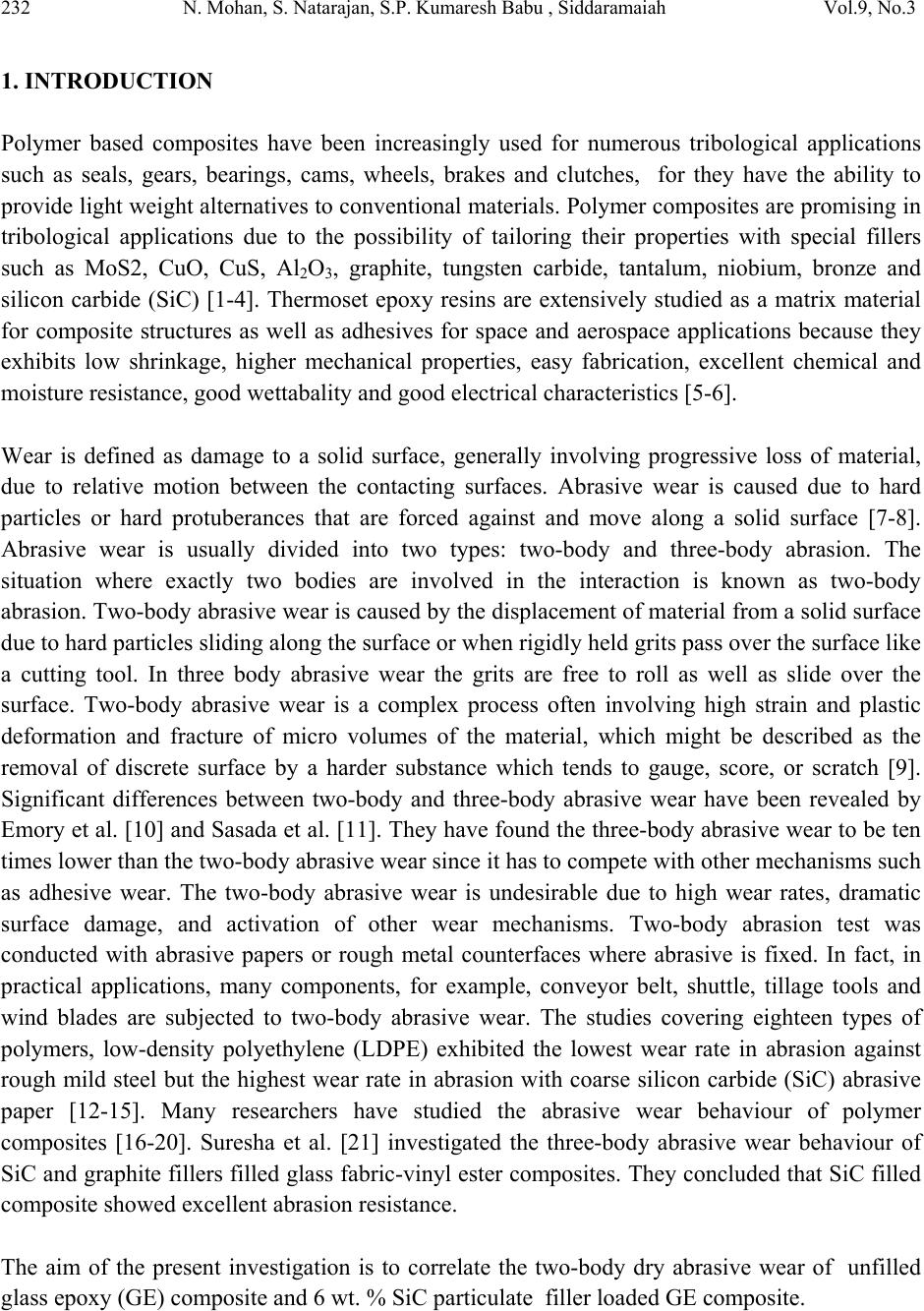 232 N. Mohan, S. Natarajan, S.P. Kumaresh Babu , Siddaramaiah Vol.9, No.3 1. INTRODUCTION Polymer based composites have been increasingly used for numerous tribological applications such as seals, gears, bearings, cams, wheels, brakes and clutches, for they have the ability to provide light weight alternatives to conventional materials. Polymer composites are promising in tribological applications due to the possibility of tailoring their properties with special fillers such as MoS2, CuO, CuS, Al2O3, graphite, tungsten carbide, tantalum, niobium, bronze and silicon carbide (SiC) [1-4]. Thermoset epoxy resins are extensively studied as a matrix material for composite structures as well as adhesives for space and aerospace applications because they exhibits low shrinkage, higher mechanical properties, easy fabrication, excellent chemical and moisture resistance, good wettabality and good electrical characteristics [5-6]. Wear is defined as damage to a solid surface, generally involving progressive loss of material, due to relative motion between the contacting surfaces. Abrasive wear is caused due to hard particles or hard protuberances that are forced against and move along a solid surface [7-8]. Abrasive wear is usually divided into two types: two-body and three-body abrasion. The situation where exactly two bodies are involved in the interaction is known as two-body abrasion. Two-body abrasive wear is caused by the displacement of material from a solid surface due to hard particles sliding along the surface or when rigidly held grits pass over the surface like a cutting tool. In three body abrasive wear the grits are free to roll as well as slide over the surface. Two-body abrasive wear is a complex process often involving high strain and plastic deformation and fracture of micro volumes of the material, which might be described as the removal of discrete surface by a harder substance which tends to gauge, score, or scratch [9]. Significant differences between two-body and three-body abrasive wear have been revealed by Emory et al. [10] and Sasada et al. [11]. They have found the three-body abrasive wear to be ten times lower than the two-body abrasive wear since it has to compete with other mechanisms such as adhesive wear. The two-body abrasive wear is undesirable due to high wear rates, dramatic surface damage, and activation of other wear mechanisms. Two-body abrasion test was conducted with abrasive papers or rough metal counterfaces where abrasive is fixed. In fact, in practical applications, many components, for example, conveyor belt, shuttle, tillage tools and wind blades are subjected to two-body abrasive wear. The studies covering eighteen types of polymers, low-density polyethylene (LDPE) exhibited the lowest wear rate in abrasion against rough mild steel but the highest wear rate in abrasion with coarse silicon carbide (SiC) abrasive paper [12-15]. Many researchers have studied the abrasive wear behaviour of polymer composites [16-20]. Suresha et al. [21] investigated the three-body abrasive wear behaviour of SiC and graphite fillers filled glass fabric-vinyl ester composites. They concluded that SiC filled composite showed excellent abrasion resistance. The aim of the present investigation is to correlate the two-body dry abrasive wear of unfilled glass epoxy (GE) composite and 6 wt. % SiC particulate filler loaded GE composite. 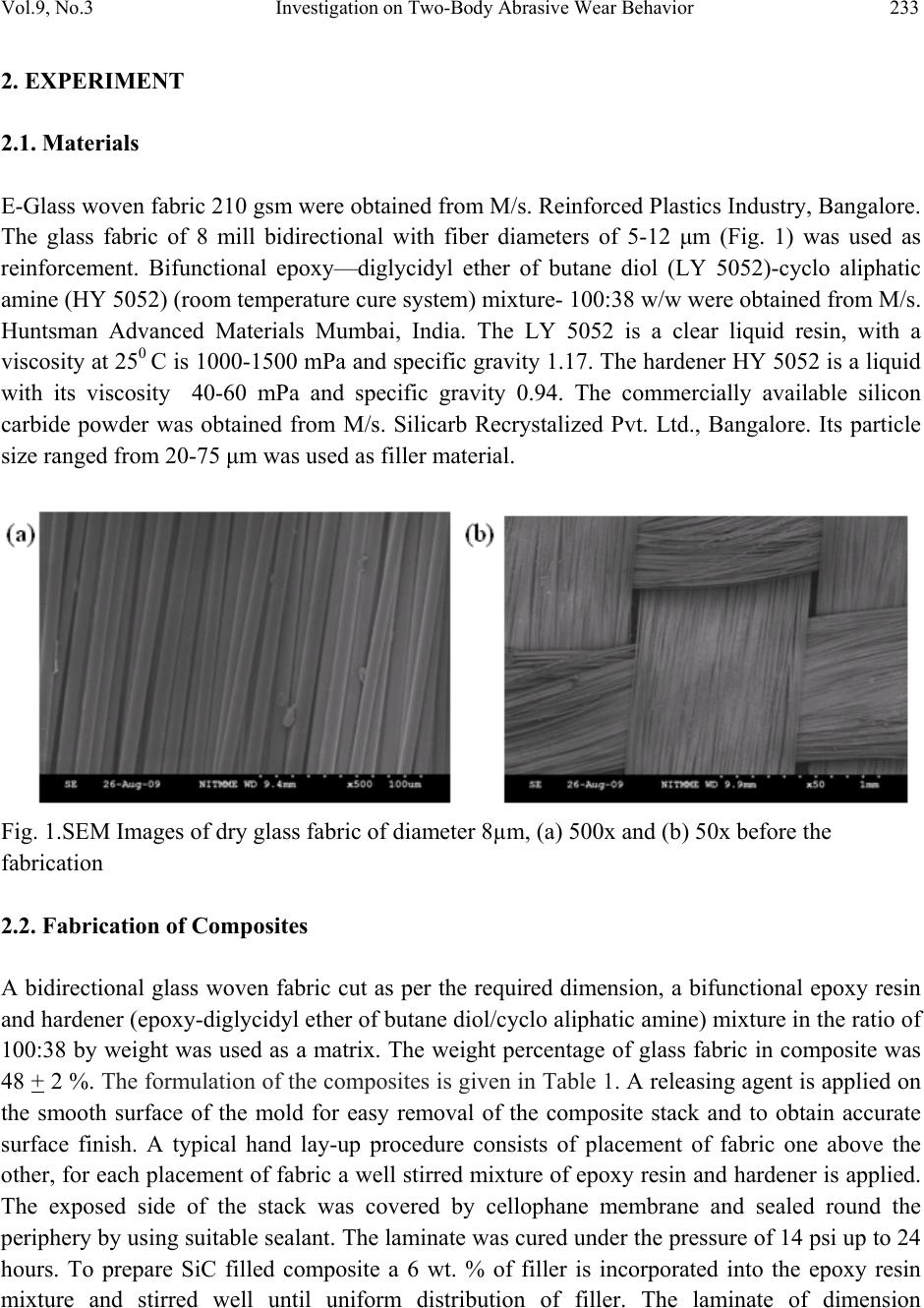 Vol.9, No.3 Investigation on Two-Body Abrasive Wear Behavior 233 2. EXPERIMENT 2.1. Materials E-Glass woven fabric 210 gsm were obtained from M/s. Reinforced Plastics Industry, Bangalore. The glass fabric of 8 mill bidirectional with fiber diameters of 5-12 μm (Fig. 1) was used as reinforcement. Bifunctional epoxy—diglycidyl ether of butane diol (LY 5052)-cyclo aliphatic amine (HY 5052) (room temperature cure system) mixture- 100:38 w/w were obtained from M/s. Huntsman Advanced Materials Mumbai, India. The LY 5052 is a clear liquid resin, with a viscosity at 250 C is 1000-1500 mPa and specific gravity 1.17. The hardener HY 5052 is a liquid with its viscosity 40-60 mPa and specific gravity 0.94. The commercially available silicon carbide powder was obtained from M/s. Silicarb Recrystalized Pvt. Ltd., Bangalore. Its particle size ranged from 20-75 μm was used as filler material. Fig. 1.SEM Images of dry glass fabric of diameter 8µm, (a) 500x and (b) 50x before the fabrication 2.2. Fabrication of Composites A bidirectional glass woven fabric cut as per the required dimension, a bifunctional epoxy resin and hardener (epoxy-diglycidyl ether of butane diol/cyclo aliphatic amine) mixture in the ratio of 100:38 by weight was used as a matrix. The weight percentage of glass fabric in composite was 48 + 2 %. The formulation of the composites is given in Table 1. A releasing agent is applied on the smooth surface of the mold for easy removal of the composite stack and to obtain accurate surface finish. A typical hand lay-up procedure consists of placement of fabric one above the other, for each placement of fabric a well stirred mixture of epoxy resin and hardener is applied. The exposed side of the stack was covered by cellophane membrane and sealed round the periphery by using suitable sealant. The laminate was cured under the pressure of 14 psi up to 24 hours. To prepare SiC filled composite a 6 wt. % of filler is incorporated into the epoxy resin mixture and stirred well until uniform distribution of filler. The laminate of dimension 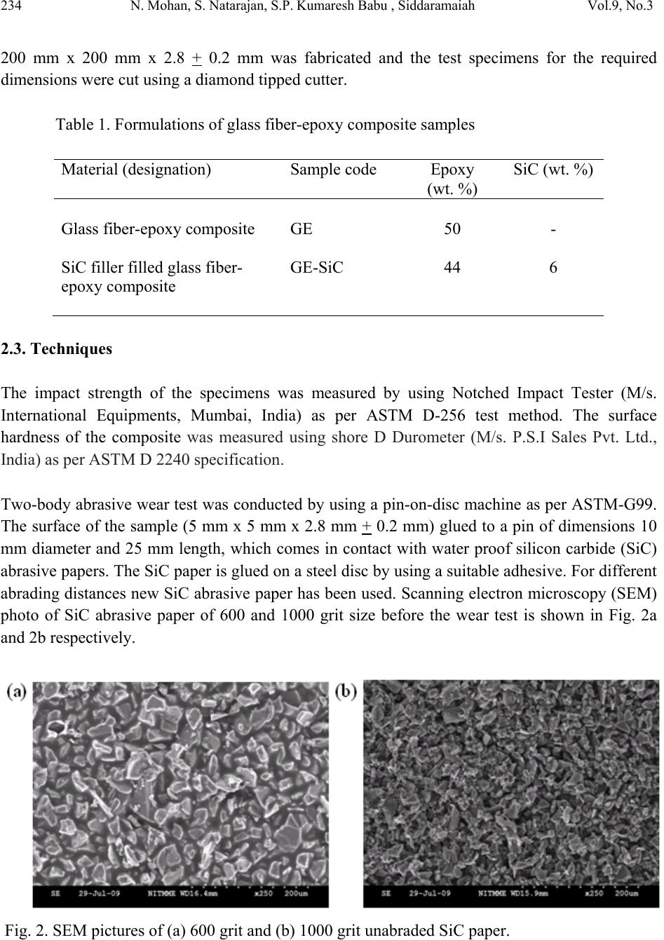 234 N. Mohan, S. Natarajan, S.P. Kumaresh Babu , Siddaramaiah Vol.9, No.3 200 mm x 200 mm x 2.8 + 0.2 mm was fabricated and the test specimens for the required dimensions were cut using a diamond tipped cutter. Table 1. Formulations of glass fiber-epoxy composite samples Material (designation) Sample code Epoxy (wt. %) SiC (wt. %) Glass fiber-epoxy composite GE 50 - SiC filler filled glass fiber- epoxy composite GE-SiC 44 6 2.3. Techniques The impact strength of the specimens was measured by using Notched Impact Tester (M/s. International Equipments, Mumbai, India) as per ASTM D-256 test method. The surface hardness of the composite was measured using shore D Durometer (M/s. P.S.I Sales Pvt. Ltd., India) as per ASTM D 2240 specification. Two-body abrasive wear test was conducted by using a pin-on-disc machine as per ASTM-G99. The surface of the sample (5 mm x 5 mm x 2.8 mm + 0.2 mm) glued to a pin of dimensions 10 mm diameter and 25 mm length, which comes in contact with water proof silicon carbide (SiC) abrasive papers. The SiC paper is glued on a steel disc by using a suitable adhesive. For different abrading distances new SiC abrasive paper has been used. Scanning electron microscopy (SEM) photo of SiC abrasive paper of 600 and 1000 grit size before the wear test is shown in Fig. 2a and 2b respectively. Fig. 2. SEM pictures of (a) 600 grit and (b) 1000 grit unabraded SiC paper.  Vol.9, No.3 Investigation on Two-Body Abrasive Wear Behavior 235 The abrasion wear test was conducted on a track of 20 mm diameter. The composite specimens were abraded against 600 and 1000 grit SiC papers at a constant load of 10 N, at 200 rpm and at four abrading distances viz., 25, 50, 75 and 100 m under multipass condition. The surface of the samples is cleaned with a soft paper soaked in acetone before the test. The specimen weight is recorded using an electronic balance (made A&D GR-300, 0.1 mg accuracy). The difference between initial and final weight of the specimen were measured as the slide wear loss. A minimum of three trials for each specimens was conducted to ensure repeatability of test data. The frictional force is measured by attaching a force transducer on pin-on-disc machine and it touches the loaded lever arm (Fig. 3). The coefficient of friction was obtained by dividing the tangential frictional force by the applied normal force. The weight loss was converted into volume loss by using a measured density of the specimen. The specific wear rate (KS) was calculated using following mathematical relation: NmmK dL V S/ 3 × Δ = (1) where, ∆V is the volume loss in m3, L is the load in Newton, and d is the abrading distance in meters. The worn surface of the composite specimen was examined using a scanning electron microscope (SEM) (S3000H, V1, Hitachi). Fig. 3. Digital Photographs of pin-on-disc machine setup, (a) Loading arrangement (i) Loaded lever arm (ii) Load cell and (iii) Force transducer, (b) Pin and disc set up (i) Pin holder with screw, (ii) Specimen with holder (iii) Water proof Silicon carbide (SiC) abrasive paper is glued on a steel disc.  236 N. Mohan, S. Natarajan, S.P. Kumaresh Babu , Siddaramaiah Vol.9, No.3 3. RESULTS AND DISCUSSION 3.1 Impact strength The measured impact strength and surface hardness of all the composites are shown in Table 2. The notched Izod impact strength of GE composite was found to be 453 J/m. The incorporation of 6 wt. % SiC particulate filler into GE composite enhanced the impact strength significantly from 453 to 615 J/m. That means about 36% improvement in fracture toughness after incorporation of SiC filler. The measured surface hardness values of GE and SiC filled GE composites were found to be 85 and 88 shore D respectively. The surface hardness value of the SiC filled GE composite has been slightly higher than the unfilled composite. This is due to SiC is comprising of tetrahedral crystals of carbon and silicon atoms with strong bonds in the lattice. This exhibits a very hard and strong material that has the ability to provide reinforcement. It is evident that the SiC filled composite showed higher impact strength and higher hardness value confirming the effect of silicon carbide as filler. Table 2. Impact strength and surface hardness of GE and GE-SiC composites Properties Method GE GE-SiC Impact strength (J /m) Notched Izod impact test ASTM D 256 453 615 Surface hardness Shore- D 85 88 Density (g/cc) - 1.30 1.36 3.2. Fracture Analysis The SEM images in Figs. 4a-b and 5a-b show the fractured surfaces (obtained by impact test) of the unfilled and SiC particulates filled composite systems, respectively. The SEM images revealed that brittle type of fracture for unfilled GE composites, along with instant multiple fractures. For unfilled GE composites the fracture was brittle and could be explained by the plastic deformation of the matrix after fiber breakage. The SEM images shown in Fig. 4b supported interfacial adhesion between fiber and matrix. Other important failure mechanisms of the composites such as fiber fracture and resin fracture were also observed in the SEM images in Fig. 4a.  Vol.9, No.3 Investigation on Two-Body Abrasive Wear Behavior 237 SEM images of the SiC particulates filled GE composite fractured surface (obtained by impact test) revealed very different fracture morphologies as shown in Fig. 5a and 5b than that of the unfilled GE composite. SiC filled GE composites revealed the simultaneous breakage of fibers and matrix, which evidenced better interfacial adhesion is shown in Fig. 5b and led to a higher impact toughness. The hard SiC particles appearance on the matrix surface was attributed to the improvement in impact strength. Other important failure features, such as a ridge in the matrix (marked as “a”), radial pattern on the fiber (marked as “b”), fiber fracture (marked as “c”) and SiC particles adhering to the surface of the fiber (marked as “d”) and good fiber matrix bonding are also evident in the SEM pictures Fig. 5b. Fig. 4. SEM images of impact fractured surface of GE composite, (a) 500 x and (b) 1000 x Fig. 5. SEM images of impact fractured surface of GE-SiC composite (a) 500 x and (b) 1000 x  238 N. Mohan, S. Natarajan, S.P. Kumaresh Babu , Siddaramaiah Vol.9, No.3 3.3. Abrasive Wear Loss The graphical plots of two-body wear loss as a function of abrading distances of unfilled and SiC particulates filled GE composites abraded against abrasive papers of 600 and 1000 grit SiC are shown in Fig. 6a and 6b, respectively. From Fig. 6a-b, it is obvious that the wear loss of composites increases with increase in abrading distances. As increase in abrading distances, the wear debris consists of shear deformed polymer matrix containing broken pulverized glass particles and SiC particles on the counter surface. The particles can either be lost from the contact zone or remain there for a fixed time as a transfer layer. In such cases, their polymer component can barrier the counter surface asperities and reduces the effective toughness, but the broken pulverized glass particles can act as a third body abrasive leading to enhanced roughening of the counter surface. Hence the wear loss increases with increase in abrading distances. The wear loss of unfilled GE is much higher than those of SiC filled GE composite. The SiC filled composite exhibited the higher wear resistance under different abrading distances. This behaviour can be attributed to the presence of SiC particles on the counter surface, which act as a transfer layer and effective barriers to prevent large-scale fragmentation of epoxy. This is also evident from the small size of the wear debris particles as determined by SEM analysis (refer Figs. 11a-b and 13a-b). Fig. 6. Wear loss of GE and GE-SiC composites as a function of abrading distance at a constant load of 10N and abraded against, (a) 600 grit and (b) 1000 grit SiC papers The lowest wear loss of 5x10⁻³ g was observed for GE-SiC composite at 25m abrading distance in 1000 grits SiC paper and highest wear loss of 13x10-3 g was observed for GE composite at 100 m abrading distance in 600 grits SiC paper. In addition, the higher wear loss was noticed at the specimens worn on 600 grit SiC paper than 1000 grit SiC paper. This is due to the larger size of the abrasive grains in 600 grit SiC paper causing greater damage to the specimen surface. In unfilled GE composites shows an excessive surface damage was seen and due to its brittle nature  Vol.9, No.3 Investigation on Two-Body Abrasive Wear Behavior 239 and the dominant cutting wear mechanism. This is also evident from the photo micrograph in Fig.10 and Fig.12. The wear data of the composites reveal that the wear behavior strongly depends on the grit size of the abrasive paper. 3.4. Coefficient of Friction The plots of coefficient of friction as a function of abrading distances of GE and GE-SiC composites at a constant load of 10 N and abraded against 600 and 1000 grits SiC papers were shown in Fig. 7a and b. The unfilled GE composite abraded against SiC paper due to rapture at the interface of the composite causes matrix debonding. From the Fig. 7a-b it was noticed that coefficient of friction decreases with increase in abrading distance for all the composites. This is due to at an increase in abrading distance some of the worn debris clog the abrasive paper and reduces the further coefficient of friction. In multipass testing as per the current studies, the passage of the specimen slides over the same wear track, the wear debris are formed and accumulates in spaces between the abrasive grits and are termed as clogging of the abrasive grits [22-24]. Fig. 8 shows the clogging of the abrasive grits with wear debris of SiC filled composite and clogging of the abrasive grits that has a dominant effect on the wear rate of SiC filled composite. Fig. 7. The plot of coefficient of friction (COF) as a function of sliding distances at a constant load of 10N and for two abrasive papers, (a) 600 grit and (b) 1000 grit SiC paper This result clearly indicates that wear mechanism of SiC filled composite is different from unfilled GE composite. The SiC filled composite shows higher coefficient of friction and less wear loss as compared to unfilled GE composite. This is due to in SiC rich surface layer and the well bonded SiC particles in matrix. During abrasion the SiC particles are well entrapped in between the specimen and the counter surface. As compared to composites was rubbed against 600 grit SiC paper (Fig.7a), in 1000 grit SiC paper (Fig.7b), it was noticed that the rate of reduction of coefficient of friction becomes slow and highest coefficient of friction was observed  240 N. Mohan, S. Natarajan, S.P. Kumaresh Babu , Siddaramaiah Vol.9, No.3 when the composite are rubbed against 1000 grits SiC paper because of more adhesive friction and less coarse action of the abrasive paper. Fouquet [25] reported that the presence of silicon in the composite matrix greatly influences the third body morphology and generates adhesive friction due to increase in coefficient of friction there by leading to less wear. Fig. 8. Clogging of the abrasive grits by SiC filled GE composites on 600 grit SiC Paper. 3.5. Specific Wear Rate The plot of specific wear rate versus abrading distance of composites at constant load of 10 N and abraded against 600 and 1000 grit water proof SiC papers is presented in Fig. 9a and 9b, respectively. The specific wear rate significantly reduces as increase in abrading distances and grit size of the SiC abrasive paper. Fig. 9 reveals that a drastic reduction in specific wear rate with an increase in abrading distances from 25 m to 50 m. However, with further increase in abrading distances above 50 m the rate of reduction in specific wear rate was found to slowing down. The variation of specific wear rate with abrading distances from 50 to 100 m follows a linear behaviour. This can be attributed to the following reasons: (i) initially when the specimen is in contact with the abrasive paper the specific wear rate is high and (ii) with increase in abrading distance some of the worn particles clog the abrasive paper and slows down further wear. At lower abrading distance, low modulus polymer matrix (soft component) was exposed to abrasion and hence, high specific wear rate. At higher abrading distance high modulus glass fabric was exposed to abrasion, which showed low specific wear rate. This is due to their (fibers) high hardness values, better resistance against abrasion and in turn, abrasive particles have to work more to facilitate failure in the fibers (i.e., much higher amount of energy is required to facilitate fiber failure). Thus, the rate at which the material is removed with respect to the abrading distance decreases (Figs. 9a and b). The obtained specific wear rates are in agreement with the findings reported in the literature [26–28]. This result clearly indicates that the specific wear rate depends on abrading distances and grit size of abrasive papers.  Vol.9, No.3 Investigation on Two-Body Abrasive Wear Behavior 241 The highest specific wear rate (KS) of 2.8 x 10⁻¹² m3 /Nm for unfilled GE composite for 600 grit SiC paper and lowest (KS) of 0.5 x 10⁻¹² m3 /Nm for SiC particulate filler filled GE composite at 1000 grit SiC paper were observed. The matrix used in this work is thermoset and the reduction in specific wear rate after incorporation of SiC filler in GE composite. Fig. 9. The plot of specific wear rate versus abrading distance for GE and SiC filled GE composites abraded against, (a) 600 grit SiC paper and (b) 1000 grit SiC paper. 4. WORN SURFACE ANALOGY The worn surface features of the composite specimen was examined using a scanning electron microscope (SEM). The SEM features of the worn surfaces of unfilled and SiC filled GE composite samples at a constant load of 10 N for two abrasive SiC papers (600 and 1000 grit) and at two abrading distances (25 and 100 m) are shown in Figs. 10-13. Fig. 10. SEM pictures of worn surface of GE samples abraded against 600 grit SiC paper at, (a) 25 m and (b) 100 m  242 N. Mohan, S. Natarajan, S.P. Kumaresh Babu , Siddaramaiah Vol.9, No.3 The surface features of unfilled GE composite worn surfaces abraded at 25 and 100 m as shown in Fig. 10a and b. SEM images of higher abrading distance Fig. 10b depicted that more damage to the epoxy matrix and glass fibers as compared with that of lower abrading distance (Fig.10a). Fig.10a evidenced the micro-cracking, chip formation, exposure of fibers, and less fiber breakage. As in Fig. 10b fiber cutting and void formation due to chips out of matrix are seen predominantly perpendicular to the wear direction. There is evidence of matrix removal and deep furrows in the epoxy matrix as shown in Fig. 10b. Furthermore, severe damage to the fibers, crushed and fragmented fibers, and delamination between fiber and matrix were noticed at higher abrading distance (Fig. 10b). Fig. 11. SEM pictures of worn surface of SiC filled GE samples abraded against 600 grit SiC paper at, (a) 25 m and (b) 100 m The abrasive wear loss of unfilled GE composite is higher than the GE-SiC composite because of the soft matrix exposed to abrasion force. The GE system showed severe matrix failure for at the initial stage of abrasion, hard abrasive particles was in contact with soft matrix resulting in severe matrix damage and the rate of material removal was very high. SEM images of worn surface of GE-SiC composite at 600 grit SiC paper at 25m showed smooth surfaces less matrix damage and matrix is well bonded with fiber and it protects the fiber in position as shown in Fig. 11a where as SEM images at higher abrading distance 100 m showed rough surface. Fig. 11b also reveals formation of fiber skin. This result clearly indicate as abrading distance increases wear loss also increases.  Vol.9, No.3 Investigation on Two-Body Abrasive Wear Behavior 243 Fig. 12. SEM pictures of worn surface of GE samples abraded against 1000 grit SiC paper at, (a) 25 m and (b) 100 m The wear behaviour was found to be varying with grit size of the abrasive papers. The surface of composite specimen abraded against 1000 grit SiC paper was less damaged (Figs.12 and 13) as compared to the specimens abraded against 600 grit SiC paper (Figs. 10 and 11) under the same test condition. The damage of the matrix and fiber were found to be much thinner and lesser for the composites abraded at 1000 grit SiC paper as compared to 600 grit SiC paper. Fig. 13. SEM pictures of worn surface of SiC filled GE samples abraded against 1000 grit SiC paper at, (a) 25 m and (b) 100 m In case of GE composites, a thin layer of matrix was eroded as shown in Fig.12a. In Fig.12b, displacement of broken fibers, debris formation and fiber skin formation followed with fiber damage were noticed. The worn surface of SEM images of SiC filler loaded composite (Fig.13a-b) showed less damage to matrix and embedded fiber as expected. This is due to the  244 N. Mohan, S. Natarajan, S.P. Kumaresh Babu , Siddaramaiah Vol.9, No.3 incorporated hard SiC particles present along with matrix on surface of the composite specimen, which acts as antiwear additive and hence retard the wear loss. 5. CONCLUSIONS The two-body wear behaviors of unfilled and SiC particulates filled GE composites were studied. The following are the salient observations made from the aforesaid investigation. • Impact test results indicate a significant improvement in impact strength (36%) after incorporation of SiC filler. • The two-body abrasive wear performance of GE and GE-SiC composites depends significantly on the abrading distances and grit size of the abrasive paper. The wear loss was found to increase in composites with the increase in abrading distances. • The enhancement on the wear resistance after incorporation of SiC filler in GE composite was generally associated with less matrix and less fiber damage and/or removal. SiC filled GE composite exhibits better wear resistance under all test conditions. • SEM observations threw light on features such as matrix fracture, inclined fiber fracture, and disorientation of transverse fibers. The unfilled GE composite worn surface features exhibits severe matrix damage, fiber exposure, fiber thinning, great damage to fiber and separation of fibers from the matrix. However, SEM studies revealed that in SiC filled GE composite severity and the extent of damage on the surface become less as noticed in the softer region owing to the presence of hard SiC particles phase. • The performance of SiC-filled GE composite is found better than unfilled GE composite. ACKNOWLEDGEMENT The authors wish to express their gratitude for the provision of the excellent experimental facilities, established under Technical Education Quality Improvement Programme (TEQIP) in the Department of Metallurgical and Materials Engineering, National Institute of Technology, Tiruchirappalli. We would also like to express our sincere thanks to the, management and principal of Dr.Ambedkar Institute of Technology, Bangalore and All India Council of Technical Education (AICTE), New Delhi for their distinguished help and valuable support during the course of this work. REFERENCES 1. K.Frieddrich, Z. Zhang, P. Klein, Mechanisms and practice (Ed. G.W. Stachowiak) John Wiley & Sons, Chichester UK (2005) 269-290. (b)  Vol.9, No.3 Investigation on Two-Body Abrasive Wear Behavior 245 2. B.J. Briscoe, L.H .Yoo, T.A. Stolarski, The friction and wear of PTFE-PEEK composites an initial appraisal of the optimum composition, Wear 108 (1986) 357- 374. 3. K.Friedrich, Z. Lu, A.M.Hager, Recent advances in polymer composites tribology, Wear 190 (1995) 139-144. 4. Bharat Bushan, Principles and Applications of Tribology. A Wiley-Interscience, (1999) 554 & 881-885. 5. J.A. Baille, Woven fabric in aerospace structures, Hand book of composites, North- Holland, Amsterdam, 2 (1989) 353. 6. George Lubin, Hand book of fiber glass and advanced plastics composites, Polymer Technology series, Van Nostrand Reinhold company (1969) 46-47, Chapter 3. 7. M.J .Neale, M. Gee.Guide to wear problems and testing for industry, New York, USA, William Andrew, 2001. 8. Xian Jiaa, Ruofei Lingb, Two-body free-abrasive wear of polyethylene, nylon 10, epoxy and polyurethane coatings, Tribol. Intl. 40 (2007) 1276–1283. 9. R. Chattopadhyay, Surface wear: Analysis, Treatment, and Presentation, ASM International, Materials Park, 2001. 10. N. Emori, T.Sasada, M.Oike, Effect of material combination in rubbing parts on the three body abrasive wear, JSLE Transactions, 30 (1985) 53-59. 11. T. Sasada, N. Emori, M.Oike, The effects of abrasive grain size on the transition between abrasive and adhesive wear, Wear (1984) 291-302. 12. P.V. Krakhmalev, J. Sukumaran, A. Gaard, Effect of microstructure on edge wear mechanisms in WC–Co, Int. J. Refract. Met. Hard Mater. (2006) 24. 13. J. Pirsoa, M.Viljus, K.Juhania, S. Letunovits, Two-body dry abrasive wear of cermets, Wear 266 (2009) 21–29. 14. J.D. Gates, Two-body and three body abrasion. A critical discussion, Wear 214 (1998) 139- 146. 15. D.C. Evans, J .K. Lancaster, The wear of polymers. In: Scott D, editor. Treatise on materials science and technology, New York, USA: Academic Press, 13 (1979) 85–139. 16. P.H. Shipway, N.K. Ngao, Microscale abrasive wear of polymeric materials, Wear 255 (2003) 742–50. 17. X. Jia, X.M. Ling, Characteristics and mechanism of abrasive wear for thermoplastic Polymers, J. Univ. Sci. Technol. Beijing 10 (2003) 44–47. 18. Y.M. Xu, B.G. Mellor, The effect of fillers on the wear resistance of thermoplastic polymeric coatings, Wear 251 (2001) 1522–1531. 19. A.A. Cenna, J. Doyle, N.W. Page, A. Beehag, P. Dastoor, Wear mechanisms in polymer matrix composites abraded by bulk solids, Wear 240 (2000) 207–214. 20. H. Cai, F.Y. Yan, Q.J. Xue, W.M. Liu, Investigation of tribological properties of Al2O3- polyimide nanocomposites, Polym. Test 22 (2003) 875–882. 21. B. Suresha, G. Chandramohan, Three-body abrasive wear behaviour of particulate-filled glass–vinyl ester composites, J. Mater. Process. Technol. 200 (2008) 306–311.  246 N. Mohan, S. Natarajan, S.P. Kumaresh Babu , Siddaramaiah Vol.9, No.3 22. E. Rabinowicz, In Friction and wear of materials. John Wiley & Sons, New York, (1995)194. 23. R.G. Bayer, In Mechanical wear prediction and prevention, Marcel Dekker Inc., New York, (1994) 23. 24. G. Srinath, R. Gnanamoorthy, Effect of organoclay addition on the two-body abrasive wear characteristics of polyamide 6 nanocomposites, J. Mater. Sci. (2007) 8326-8333. 25. S. Fouquet, M. Rollin, R. Pailler, X. Bourrat, Tribological behaviour of composites made of carbon fibers and ceramic matrix in the Si–C system, Wear (2007). 26. B.J. Briscoe, L.H. Yoo, T.A. Stolarski, The friction and wear of poly (tetrafluoro ethylene)- poly(ether ether ketone) composite: An initial appraisal of the optimum composition, wear 108(1986)357-374. 27. B.M. Sole, A. Ball, On the abrasive wear behaviour of mineral filled polypropylene, Tribol. Int. 29 (1996) 457. 28. J.K. Lancaster, Abrasive wear of polymers, Wear, 14 (1969) 223-239. |