Journal of Electromagnetic Analysis and Applications
Vol. 3 No. 3 (2011) , Article ID: 4393 , 6 pages DOI:10.4236/jemaa.2011.33014
Electromagnetic Pulse Coupling inside a Rectangular Enclosure with an Aperture
![]()
1Department of Electrical Engineering, Mashhad Branch, Islamic Azad University, Mashhad, Iran; 2Department of Electrical Engineering, Shahr_e_Rey Branch, Islamic Azad University, Tehran, Iran; 3Department of Electrical Engineering, Science and Research Branch, Islamic Azad University, Tehran, Iran.
Email: m.bahadorzadeh@mshdiau.ac.ir, alotfi@iust.ac.ir, mn_moghaddasi@yahoo.com
Received January 26th, 2011; revised February 12th, 2011; accepted February 13th, 2011.
Keywords: Electromagnetic Pulse, TLM, Shielding, Rectangular Enclosure
ABSTRACT
The transmission line matrix time domain (TLM-TD) method is used to simulate the electromagnetic pulse (EMP) coupled inside a shielding box with an aperture. Simulations for different electromagnetic pulses regarding to different rise time and fall time have been performed. The results for shielding effectiveness of these different excitations have been presented. A simple method that uses an extra metal for reducing the interference has also been proposed and tested.
1. Introduction
In the recent years by developing the electronic technology, the integrated level of the circuits has been increased and its working voltage is getting lower and lower, which increases the sensitivity of the circuit to electromagnetic interference (EMI) and thus requires more considerations for making environmental compatibility.
Electromagnetic pulse recently has been attracted more attention as an EMI source. Generally, sensitive electronic apparatus and circuits are usually shielded against the external interference EMP with a metal shielding box. The electronic apparatus and circuits inside a metal shielding box are affected by EMP mainly through two alternatives.
Firstly, the EMP coupling its energy to circuits through apertures of the metal box directly, because the shielding box all have apertures used as connection canals, ventilations, or other uses. In [1] a Method of Moment/ Finite Difference Time Domain (MOM /FDTD) hybrid algorithm is used to calculate the Electromagnetic pulse coupling with a complicated shielding box. In [2] and [3], TLM integral equation (TLMIE) and hybrid TLM integral equation method are used to solve radiation problems. In [4] the Transmission Line Matrix (TLM) method has been developed for the electromagnetic compatibility (EMC) analysis of circuits and equipment packaging.
In [5], a novel time-domain wave propagator, based on the transmission line matrix (TLM) technique, is introduced. A two-dimensional (2-D) TLM algorithm is modified and the sliding window technique is applied to analyze ground wave propagation characteristics.
In [6] the timeand frequency-domain transmission line matrix methods have been developed and shown to be effective and powerful in solving electromagnetic problems.
An analytical formulation has been developed for the shielding effectiveness of a rectangular enclosure with an aperture in [7].
In [8] the transmission-line method (TLM) was applied to the solution of shielding problems commonly encountered in equipment cabinet design. The shielding effectiveness (SE) of a metallic box, effect of parameters like the size of the aperture, the place of aperture, and influence of using extra wall has also been investigated in [9].
In this paper, Symmetrical Condensed Node (SCN) of TLM-Time Domain method is used to simulate the coupled electric field of EMP inside a shielding box with a rectangular aperture. Results show that rise time and fall time of electromagnetic pulse has a significant effect on coupled energy into the box.
2. Theory
The basic theory of solving Maxwell’s equations in the

Figure 1. Symmetrical condensed node.
TLM method is given in [9,10], where a method for scattering was used. This method was then advanced to distributed node 3-D model that is based on interconnection of shunt and series networks. Due to the complexities in the topology of this model, a node known as Symmetrical Condensed Node (TLM-SCN) was then introduced in [10]. As Shown in Figure 1, a node is made up of 12 interconnected lines and is represented via a 12 × 12 scattering matrix.
At such a node, propagation of the wave occurs in two main stages:
1) 12 voltage pulses incident at the same time to 12 ports and then all scatter using the scattering matrix.
2) Returned pulses are the incident pulses for neighbor nodes in the next time step.
This process will then continuous. Resulting in:


 (1)
(1)
where  is reflected voltage,
 is negative side of Y axis and x represents direction of electric field vector. These formulae could be written in matrix form as,
 (2)
(2)
In which  is the incident voltage vector
  is the reflected voltage vector, S is the scattering matrix and C is the interconnection matrix. In the TML-SCN method characteristic impedance of all lines are the same,
  and
and  of the medium are modeled using 6 extra open and short circuit ports. To analyze an electromagnetic problem, the space of the structure is first divided into several meshes, for each the above nodes are considered. To take into account the feed excitation, a pulse is incident on the related nodes. Finally by using following mapped relations between voltage pulses and electrical and magnetic fields,
  and
and  fields could be obtained.


 (3)
(3)
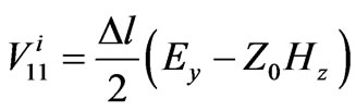
In Equation (3),  is incident pulse voltage at port 1,
  is mesh size and
 is characteristic impedance.
3. Shielding Effectiveness Analysis
The ability of an enclosure to reduce the emission or to improve the immunity of electronic equipment from high frequency interference is characterized by its shielding effectiveness (SE), which is defined as the ratio of the field strength in the presence of the enclosure Es, to that in its absence E. Thus it can be expressed in decibels, as,
 (4)
(4)
Shielding effectiveness can be calculated by classic analytical techniques or by numerical simulations. Analytical formulations provide a faster means of estimating the SE. However, since these methods are based on simplifying assumptions, they cannot provide sufficient accuracy to meet the design specifications when the shielding structure is geometrically complex.
3.1. Problem Definition
Figure 2 shows a typical metallic enclosure with a rectangular aperture of dimension w × l illuminated by a plane wave. All sides are assumed perfectly conducting with an infinitesimal thickness. The observation point is located at a distance p away from the aperture inside the enclosure and on a line normal to the aperture and passing through the center of the enclosure.
In order to evaluate the shielding effectiveness of a rectangular shielding with aperture the following structure for simulation was arranged (see Figure 2). For a fine mesh and rigorous TLM simulation, the size of the

Figure 2. A typical enclosure with a rectangular aperture.

Figure 3. Shielding structure and realization by using symmetrical & radiation planes.
meshes should be as small as possible. So the symmetrical PEC and PMC walls were used as shown in Figure 3. An electromagnetic pulse is simulated by a Transverse Electric-Magnetic (TEM) wave in far field which has only a z directed distributed electric field.
Perfectly electric and magnetic conducting walls are placed at z = a/2 and x = b/2 symmetry planes, respectively. Thus, only a quarter of the structure needs to be solved and the necessary memory and processing time requirement will be reduced by a factor of four. The internal dimensions of enclosures are assumed to be 120 mm × 300 mm × 300 mm (a = 120 mm, b = d = 300 mm).
For all simulations, in order to produce a plane wave radiation toward the enclosure, a free space volume of 120 mm × 300 mm × l00 mm is placed in front of the aperture. A simple absorbing boundary condition is applied in the free space region. The final structure with symmetrical planes is depicted in Figure 3.
A non uniform mesh was used resulting in a TLM cell size of Δx = Δy = 5 mm, Δz = 2.5 mm. The walls of the cavity were considered as infinitesimally thin metallic walls. In this study EMP is considered as the source of EMI which causes undesired coupling of energy inside the shielding structure. By choosing for each time step in TLM simulation, the selected mesh size should satisfy the stability condition:
 and the structure must be modeled perfectly with a fine mesh.
The electric field of a typical EMP has been shown in Figure 4.
3.2. Shielding Effectiveness for Different Pulses
As it can be seen in Figure 4, an EMP pulse consists of two exponential functions that each of them has different rise time.
 (5)
(5)

Figure 4. Electric field of a typical EMP.
The a and b parameters determine the rise time and fall time of the main signal. In order to study the effect of rise time and fall time on coupled energy into the shield, electromagnetic pulses with different rise times are used as excitation sources. First the shielding effectiveness of box for three different excitation with 1 ns and 7 ns rise time and Gaussian is evaluated. As it was expected the shielding effectiveness is equal for three different cases. This fact can be seen in Figure 5.
However the shielding effectiveness for three different excitations is the same but the coupled electric field isn’t. The result of Electric field in z direction in the center of metallic box is depicted in Figure 6.
The electric field reaches its maximum in resonant frequency of the shielding box. The frequency resonant of metallic box can be seen in Figure 5. The resonant frequency is about 620 MHz that the electric field has reached its peak. For explanation of this graph the frequency spectrum of different EMP’s should be investigated. By taking a Laplace transform of (5), F(s) results as following,
 (6)
(6)

Figure 5. Shielding effectiveness of structure (EMP as a source of excitation).

Figure 6. Ez coupled into shield structure by EMP as source of excitation.
That it has two poles at s = a and s =
 b so that the graph of the magnitude of the F(s) could be generally like the Figure 7.
It is clear that by increasing the frequency, magnitude of spectrum of EMP’s will decrease. The magnitude of different EMP pulses and a Gaussian pulse in frequency domain are shown in Figure 8. It could be inferred from this figure that an electromagnetic pulse with lower rise time has greater frequency magnitude in lower frequency and this pulse could couple more energy into the shield structure especially in resonant frequency.
3.3. Coupled Energy from the Pulses with the Same Energy
As it has been shown in previous section, the shape of the pulse has a crucial effect on coupled electric field but the effect of the energy of pulses should be considered. For investigation of this effect three different pulses with the same energy according to the following relation were used and a simulation has been performed.
 (7)
(7)

Figure 7. Magnitude of Fourier transform of a typical electromagnetic pulse.

Figure 8. Magnitude of different EMPs in frequency domain.
In this simulation three different pulses, regarding to different rise times and fall times have been used but both of them have the same energy. The first pulse has a 1 ns rise time and 11 ns fall time and the third one has 9 ns rise time and 26 ns fall time (see Figure 9).
As can be seen in Figure 10, the coupled electric field of an EMP with 1 ns rise time and 11 ns fall time is about 20 dB greater than another pulse. This issue could be explained in regard of having a bigger magnitude for these kinds of pulses in frequency spectrum.
3.4. Shielding Effectiveness of a Box with Double Walls
A shielding metallic box with extra shielding wall is shown in Figure 11. In [9] it has been shown that by adding an extra wall, the shielding effectiveness can significantly be improved. In this study also the effect of an extra shielding wall on the deviation of resonant frequency has been investigated. An EM Pulse with 1 ns rise time and 11 ns fall time illuminate the structure which is depicted in Figure 11. The distance between stages is 50 mm (s = 50 mm). As it was expected, the amplitude of

Figure 9. EM pulses with different rise time and fall time with the same energy.

Figure 10. Ez coupled into shield structure by EMPs with same energy.
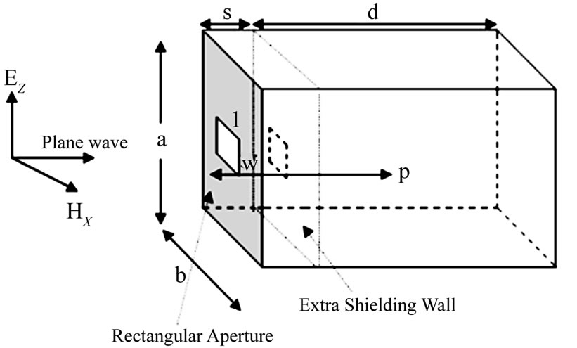
Figure 11. A shielding metallic box with extra wall.
the electric field in Z direction in center of metallic box has reduced about 20 dB in resonant frequency. This reduction in amplitude of electric field could be explained in this way that some of those coupled energies are trapped between two shielding walls so that the amount of coupled energy inside the box is reduced.
The attenuation of the EM fields inside the enclosure is happened because a part of EM wave is reflected by electrical walls of shielding Box but in the resonant fre-

Figure 12. Comparison of electric field in z direction in the center of single and double wall metallic box.

Figure 13. Comparison of electric field in z direction in the center of double wall metallic box.
quency the electromagnetic field inside the box is amplified.
It is clear that by increasing the distance between two stages, the amplitude of electric field inside the box will be reduced because by increasing the volume between the stages more energy will be trapped between walls.
In Figure 13 the shielding effectiveness as a function of distance between two stages (s) has been presented. Simulation was performed for three different distances (25 mm, 50 mm & 75 mm). The resonant frequency as expected has not changed because the dimensions of cavity resonator were kept constant.
4. Conclusions
The electromagnetic pulse effects on shielding enclosures with embedded apertures are studied using transmission line matrix time domain method. The symmetrical walls are used to reduce all simulation resources by a factor of 4. The effects of EMP rise and fall times over the coupled distributed electric field energy through the aperture were studied and shielding effectiveness parameter and coupled electric field strength are both analyzed for different excitations. The effect of an extra wall to reduce the unwanted interference were also modeled and widely interpreted.
REFERENCES
- M. Edrisi, “A Modeling Technique for Electromagnetic Compatibility of Enclosures in System Integration and Performance Analysis,” Ph.D. Dissertation, University of South Australia, Adelaide, March 2000.
- L. Pierantoni, S. Lindenmeier and P. Russer, “Efficient Analysis of Microstrip Radiation by the TLM Integral Equation (TLMIE) Method,” 1998 IEEEMTT-S International Microwave Symposium, Baltimore, Vol. 3, June 1998, pp. 1267-1270.
- L. Pierantoni, S. Lindenmeier and P. Russer, “A Hybrid Time Domain TLM Integral Equation Method for Solution of Radiation Problems,” 14’h Annual Review of Progress in Applied Computational Electromagnetic (ACES), Monterey, March 1998, pp. 320-325.
- D. Johns, F. Centola and B. Shusterman, “TLM Simulation of RF Emissions and Confirmation of Results through Testing,” IEEE International Symposium on Electromagnetic Compatibility, Fort Lauderdale, July 2007, pp. 1-4. doi:10.1109/ISEMC.2007.157
- M. O. Ozyalcin, F. Akleman and L. Sevgi, “A Novel TLM-Based Time-Domain Wave Propagator,” IEEE Transactions on Antennas and Propagation, Vol. 51, No.7, July 2003, pp. 1679-1680. doi:10.1109/TAP.2003.813624
- Z. Z. Chen and M. M. Ney, “On the Relationship between the Time-Domain and Frequency-Domain TLM Methods,” IEEE Antennas and Wireless Propagation Letters, Vol. 7, 2008, pp. 46-49. doi:10.1109/LAWP.2008.915803
- M. P. Robinson, T. M. Benson, C. Christopoulos, J. F. Dawson, M. D. Ganley, A. C. Marvin, S. J. Porter and D. W. P. Thomas, “Analytical Formulation for Shielding Effectiveness of Enclosures with Apertures,” IEEE Transactions Electromagnetic Compatibility, Vol. 40, No. 3, 1998, pp. 240-248. doi:10.1109/15.709422
- C. Christopoulos, “Application of the TLM Method to Equipment Shielding Problems,” IEEE International Symposium on Electromagnetic Compatibility, Vol. 1, 1998, pp. 188-193. doi:10.2528/PIERL07110706
- M. Bahadorzadeh and M. N. Moghaddasi “Improving the Shielding Effectiveness of a Rectangular Metallic Enclosure with Aperture by Using Extra Shielding Wall,” Progress in Electromagnetic Research, Vol. 1, 2008, pp. 45-50.
- P. B. Johns, “A Symmetrical Condensed Node for the TLM Method,” IEEE Transactions on Microwave Theory, Vol. MTT-35, No. 4, April 1987, pp. 370-377.