Natural Science
Vol.5 No.10(2013), Article ID:37357,9 pages DOI:10.4236/ns.2013.510131
Impact of the light intensity variation on the performance of solar cell constructed from (Muscovite/TiO2/Dye/Al)
![]()
Department of Physics, Sudan University of Science and Technology, Khartoum, Sudan; mahmoudhilo2gmail.com, rawia_abdalgani@yahoo.com, rawia@sustech.edu
Copyright © 2013 R. Abd Elgani et al. This is an open access article distributed under the Creative Commons Attribution License, which permits unrestricted use, distribution, and reproduction in any medium, provided the original work is properly cited.
Received 9 July 2013; revised 9 August 2013; accepted 16 August 2013
Keywords: Intensity of Light; Solar Cell Efficiency; Fill Factor; Solar Photovoltaic
ABSTRACT
In this work, the influence of the light intensity as one of the parameters that control the solar cell is studied. The effect of the other main variables, such as temperature, rotation per Minuit of the spin coating instrument, and the samples concentration, was found to be in conformity with other results, but unfortunately the intensity of light does not increase the solar cell efficiency, and fill factor, by other words it was found to play only a secondary role.
1. INTRODUCTION
Man has needed and used energy at an increasing rate for his sustenance and well-being ever since he came on the earth a few million years ago. Primitive man required energy primarily in the form of food. He derived this by eating plants or animal which he hunted. Subsequently he discovered fire and his energy needs increased as he started to make use of wood and other biomass to supply the energy needs for cooking as well as for keeping himself warm. With the passage of time, man started to cultivate land for agriculture. He added a new dimension to the use of energy by domesticating and training animals to work for him. With further demand for energy, man began to use the wind for sailing ships and for driving wind mills, and the force of falling water to turn water wheels. Till this time, it would not be wrong to say that the sun was supplying all the energy needs of man either directly or indirectly and that man was using only renewable source of energy [1].
The Industrial Revolution which began with the discovery of the steam engine brought about a great many changes. A new source of energy, nuclear energy, came on the scene after the Second World War. Thus today, every country draws its energy needs form a variety of sources. We can broadly categorize these sources as commercial and noncommercial, for instance solar energy. The solar energy option has been identified as one of the promising alternative energy sources for the future. The nature of this source, its magnitude and its characteristics have been described, and a classification of the various methods-direct and indirect-for utilizing solar energy has been given [2].
Due to the nature of solar energy, two components are required to have a functional solar energy generator. These two components are a collector and a storage unit. The collector simply collects the radiation that falls on it and converts a fraction of it to other forms of energy (both electricity and heat). Solar energy can be directly converted to electricity energy. Most of tools were designed to be driven by electricity, so if you can create electricity through solar power, you can run almost anything with solar power. The collectors that convert radiation into electricity can be either flat plane or focusing collectors, and the silicon components of these collectors are photo voltage cells.
Photo voltage cells, by their very nature, convert radiation to electricity. This phenomenon has been known for well over half a century, but until recently the amount of electricity generated was good for title more than measuring radiation intensity.
The modern age of solar power technology experimenting with semiconductors accidentally found that silicon doped with certain impurities was very sensitive to light.
This resulted in the production of the first practical solar cell with a sunlight energy conversion efficiency of around 6 percent. Solar cells can be made from a number of materials other than silicon, and formed in a variety of designs; cells are classified both by material and by the type of junction. For instance, the materials used in solar cells today are cadmium sulfide, gallium arsenide, titanium dioxide and dyes.
However, with the current technology, the cost per watt is rather high due to the high cost of manufacturing silicon-based solar cells. The cost per watt can be lowered by two ways: lower the manufacturing cost, or increase the amount of power output for the same cost. The latter is related to efficiency of the device. Clearly, a more efficient way converting sunlight into energy needs to be researched in order to make solar cell technology economically viable. Most traditional solar cells rely on a semiconductor (typically silicon) for both light absorption and charge transport. A fairly new, promising method separates these functions. Organic dyes (dye sensitizers), which are sensitive to light, can absorb a broader range of the sun’s spectrum [1,2]. Dye sensitized solar cell is considered the low-cost solar cell. This cell is extremely promising because it is made of low-cost materials and does not need elaborate apparatus to manufacture to produce it compared with other type of solar cell. This led me to use this type of material that has attracted academic and industrial research groups not only because of their theoretically interesting properties but also because of their technologically promising future. More researchers used this material to made solar cells with different technologies.
2. PROBLEMS WITH CURRENT SOLAR CELL TECHNOLOGY
When it comes to solar technologies, one of the biggest issues is with that of photovoltaic panels or solar cells. These panels are made in various ways and depending on their production determine their efficiency and cost. By far the cheapest solar cell is that of the thin film type which is used to make flexible panels. This process is also cheaper but likewise their efficiency is not all that to be desired.
You also have the casting of existing silicon crystals into a panel which is the most predominant form of solar cell manufacture but this is more expensive and while efficiency may increase, the costs of these panels may be too great for the average person.
You also have the creation of silicon crystals which is a manmade process of dissolving them and reforming them only to be thinly sliced and turned into a PV panel. These are the second most efficient solar cell with efficiencies closing in on the 15% mark, but they are also consuming to produce which also means very expensive.
The final type of solar cell is also the newest that is available to the general market. While concentrated PV panels are not new as they have been utilized in space for well over a decade, they are new to the general market. These PV panels are by far the most expensive and they are multiple layers of solar cells stacked on top of each other. The concentrated PV panel can see efficiencies upwards of 40% - 50% which is getting closer to what the world needs, but their cost is something else altogether; some of them costing well over $10,000 for a single cell that can fit in the palm of your hand.
In most cases the cost of solar cells can be so great that is will not even cover the life expectancy of the cell which means it would cost more than using your utility feeds. Solar power created by solar cells is also considered by far to be the most expensive means of producing electricity. You cannot use a solar cell at night time so you either have to store the energy at higher costs or turn to fossil fuels for this night time power production. Let’s not forget the fact that solar cells only produce direct current and when coupled to the necessary inverter you end up losing another 15% of that power in heat.
While there is much promise in solar cells; delivery of an efficient and inexpensive PV panel in this lifetime may be asking too much. However it is important to remember that solar cells are not the only way of producing electricity from the sun. While solar cells use the sun’s light to create electricity, solar thermal systems use the sun’s heat to produce and is by far much more efficient. While no good in low light conditions, the heat created by the sun can be stored in a number of mediums from graphite to molten salt which means that within no time the ability to store this energy all night long will be upon us. Furthermore solar thermal is much cheaper than solar cell energy production and it is why the vast majority of solar power plants around the world use this form over any other [3].
3. SOLAR PHOTOVOLTAIC
Solar cells convert the solar radiation directly into electricity using photovoltaic cell or the so called solar cells generate electromotive force as a result of absorption of ionizing radiation. Major advantage of solar cells over conventional methods of power systems are:
Photovoltaic effect without going through a thermal process, Solar cells are reliable, modular, durable, and generally maintenance free and therefore, suitable even in isolated and remote areas. Solar cells are quiet, benign, and compatible with almost all environments, respond instantaneously to solar radiation, and have an expected lifetime of 20 or more years. Solar cells can be located at the place of use and hence no distribution network is required. Like other solar devices solar cells also suffer from some disadvantages, such as:
The conversion efficiency of solar cells is limited to about 30%. Since solar intensity is generally low, large areas of solar cell modules are required to generate sufficient useful power. The present costs of solar cells are comparatively high, making them economically uncompetitive with other conventional power generation methods for terrestrial applications, particularly where the demand of power is very large. Solar energy is intermittent and solar cells produce electricity when sun shines and in proportion to solar intensity. Hence, some kind of electric storage is required making the whole system more costly. However, in large installation, the electricity generated by solar cells can be fed directly into the electric grid system [4].
3.1. Photovoltaic Conversion
The devices used in photovoltaic conversion are called solar cells. When solar radiation falls on these devices, it is converted directly into dc electricity. The principal advantages associated with solar cells are that they have no moving parts, require little maintenance, and work quite satisfactorily with beam or diffuse radiation. Also they are readily adapted for varying power requirements because a cell is like a “building block”. The main factors limiting their use are that they are still rather costly and that there is very little economy associated with the magnitude of power generated in an installation.
However, significant developments have taken place in the last few years. New types of cells have been developed, innovative manufacturing processes introduced, conversion efficiencies of existing types increased, costs reduced and the volume of production steadily increased. The present annual world production of photovoltaic devices is already about 60 M W. As a result of the above development, solar cells are now being used extensively in many consumer products and appliances [4].
3.2. Application
In spite of the high initial cost, photovoltaic systems are being used increasingly to supply electricity for many applications requiring small amount of power. Their costeffectiveness increases with the distance of the location (where they are to be installed) from the main power grid lines.
Some applications for which PV systems have been developed are:
1) Pumping water for irrigation and drinking.
2) Electrification for remote villages for providing street lighting and other community services.
3) Telecommunication for the post and telegraph and railway communication network.
In addition, in developed countries solar cells are being used extensively in consumer products and appliances [4].
4. PRINCIPLE OF SOLAR CELL WORKING
Two important steps are involved in the principle of a solar cell. These are:
Creation of pairs of positive and negative charges (called electron-hole pairs) in the solar cell by absorbed solar radiation. Separation of the positive and negative charges by a potential gradient within the cell, for the first step to occur, the cell must be made of a material which can absorb the energy associated with the photons of sunlight. The energy (E) of a photon is related to the wavelength (λ) by the equation [5]:
 (2.2)
(2.2)
Where h is Plank’s constant = 6.62 × 10⁻³⁴ J.s, and c = velocity of light = 3 × 10⁸ m/s.
Substituting these values, we get:
 (2.3)
(2.3)
Where E is in electron-volt (eV) and λ is in µm.
The only material suitable for absorbing the energy of the photons of sunlight are semiconductors like silicon, cadmium supplied, gallium arsenide, titanium oxide, etc. In a semiconductor, the electrons occupy one of two energy bands—the valence band and the conduction band. The valence band has electrons at a lower energy level and is fully occupied, while the conduction band has electron at a higher energy level and is not fully occupied. The difference between the energy levels of the electrons in the two bands is called the band gap energy [6]. Photons of sunlight having energy E greater than the band gap energy E g are absorbed in the cell material and excite some of electrons. These electrons jump across the band gap from the valence band to the conduction band leaving behind holes in the valence band. Thus electronhole pairs are created.
The electron in the conduction band and holes in the valence band are mobile. They can be separated and made to flow through an external circuit (thereby executing the second step of the photovoltaic effect) if a potential gradient exists within the cell. In the case of semiconductors the potential gradient is obtained by making the cell as sandwich of two types, p-type and n-type. The energy levels of the conduction and valence bands in p-type are slightly higher than the corresponding levels in n-type. Thus when a composite of two types of material is formed, a jump in energy levels occurs at the junction interface as in Figure 1. This potential gradient is adequate to separate the electrons and holes, and cause a direct electric current-to flow in the external load [7,8].
In a semiconductor cell, the junction is the region separating the n-type and p-type portions. Solar cells can be made from many semiconductors material for example, titanium oxide (TiO2) [9].
4.1. Current-Voltage Charecteristics
The behavior of a solar cell is displayed by plotting its current-voltage characteristic. A typical characteristic curve is shown below in Figure 2.
The intercepts of the curve on the x-axis and y-axis are called the short circuit current ISC and the open circuit voltage Voc the ratio between them called characteristic resistance
 (2.4)
(2.4)

Figure 1. Titanium dioxide structure and formula.

Figure 2. Principle of solar cell working.
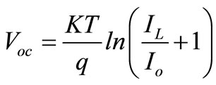 (2.5)
(2.5)
Where  = Constant,
  = Light generation current and
  = Saturation Current.
 (2.6)
(2.6)
The maximum useful power corresponds to the point on the curve which yields the rectangle with the largest area. We denote the values of current and voltage yielding the maximum power by the symbols  and
and  [10].
[10].
The ratio
 (2.7)
(2.7)
Is called the fill factor (FF) of the cell. Its value obviously ranges between 0 and 1. The maximum conversion efficiency of a solar cell is given by the ratio of the maximum useful power to the incident solar radiation. Thus
 (2.8)
(2.8)
Where IT = incident solar flux and Ac = area of the cell.
For an efficient cell, it is desirable to have high values of fill factor, short circuit current and open circuit voltage. From solid state physics theory, expressions can be derived for each of these quantities. The expressions show that high values of Isc are obtained with low band gap materials, while high value of Voc and FF are possible with high band gap materials. Thus if theoretical values of η m are calculated for different values of E g, it is obvious that a maximum value would be obtained at some value of E g [10].
5. MATERIALS USED IN THIS WORK
The element Titanium was discovered in 1791 by William Gregor, in England. Gregor spent much of his time studying mineralogy, which led him to his discovery. Titanium dioxide is even used in food stuffs [11,12].
Titanium dioxide is a fascinating low-cost material exhibiting unique properties of stability and photo activity, leading to clean technologies in environmental remediation and energy conversion of sunlight, However, conventional high-temperature processing of Titania is a technological limitation beyond energy consumption, being a handicap for practical applications in areas such as the preparation of hybrid organic/TiO2 materials or devices thermo labile substrates. Titanium oxide is also used as a semiconductor [13]. When titanium dioxide (TiO2) is exposed to near ultraviolet light, it exhibits strong bactericidal activity Figure 3. Anatase phase of TiO2 film was prepared by anodizing pure titanium coupons (substrate). We observed wide distribution of TiO2 particles ranging from submicron to nanometer sizes, fully covering the substrate forming a thin film on anodizing, with the formation of a thin film of TiO2 [14].
Dye-sensitized solar cell is considered the low-cost solar cell. This cell is extremely promising because it is made of low-cost materials and does not need elaborate apparatus to manufacture. So it can be made in different way allowing more players to produce it than any other type of solar cell. In bulk it should be significantly less expensive than older solid-state cell designs. A dye-sensitized solar cell (rhodamine B) is a relatively new class of low-cost solar cell that belongs to the group of thinfilm solar cells [15]. It is based on a semiconductor formed between a photo-sensitized anode and an electrolyte, a photo electrochemical system. Rhodamine B is an amphoteric dye, although usually listed as basic as it has an overall positive charge. It is most commonly used as a fluorochrome, an example being in mixture with auramine O to demonstrate acid fast organisms. The chemical structure of Rhodamine B is as shown below [16].
Physical properties Mica Group is a complexity of alumino silicate that consists of potassium, magnesium, iron (Fe). Mostly, mica is found in Granite Rhyolite, Phyllite or Mica Schist. There are two types of mica group;
1) Muscovite or white mica, formula KAl2 (AlSi3O10) (OH)2.
2) Biotite or black mica, formula K (Mg, Fe)3 (AlSi3O10) (OH)2 [18].
Muscovite and phlogopite are used in sheet and ground forms Figure 4 [18].
6. THE EXPERIMENTAL WORK
A 0.35 g of the rhodamine B dye was accurately weighed and dissolved in 25 ml ethanol, a 0.1 g of TiO2 was accurately weighed and a fusion mixture composed

Figure 3. Titanium dioxide (TiO2) is exposed to near ultraviolet light.


Figure 4. Mica sheets.
of 1 g of sodium-carbonate and 0.8 g of ammonium sulphate. The sample and the fusion mixture were well mixed by means of a glass rod in a porcelain crucible and put into an electric furnace for 2.5 hours at 1200˚C. After cooling the content of crucible were dissolved with dilute sulphuric acid, heating to boiling till the contents were completely dissolved and then the solution was cooled and the volume was completed to 100 ml with distilled water in a volumetric flask.
7. SAMPLE PREPERATION
Our samples were prepared by 0.05 g of TiO2 solution. The prepared solution was spin coated on the mica substrate for 60 sec and prepared by 0.35 g of rhodamine B dye solution. This solution was divided into three portions doped with iodine under three concentrations 0.05 g, 0.1 g, and 0.2 g. The prepared four concentrations solution were spin coated on the mica substrate at about 600 rpm for 60 sec in order to yield a thin uniform film. The spin coating technique device was removed using acetone, and the surface was washed by distilled water and methanol, then rinsed with acetone and dried. Finally aluminum strips were evaporated on top of the (Muscovite/TiO2/Dye) sensitize at a pressure of 1 × 10⁻⁶ mbar, using Coating Unit (Edwards High Vacuum Evaporation Unit model 19E6/196). These samples (9 samples) were connected in serial circuit with nanometer, voltmeter and rheostat. The measurements were taken at the room temperature (300 K). I-V measurement in dark and under illumination was carried out by mounting the sample in a sample holder metal, having area about 1 cm2. The current measured using Nano-Ampere meter (model 841B) and voltage measured using multi meter device. The intensity of the incident light was measured (0.2 and 0.4 W/m2) using a light meter (model D-10559). Michelson interferometer was used in thickness measurement of (Muscovite /TiO2/Dye/Al) layer which is coated on mica substrate.
8. RESULTS
Figures 5-16 show the results obtained within the experiment in which the present work discuss, the main parameter meant in this experiments is the light intensity I, (two values for I were chosen 0.2 w/m2 and 0.4 w/m2), beside the all parameters used in the work [effect]. Also the current—voltage plots give an exponential relation, which lead directly to the evaluation of the physical characteristics of solar cell, such as efficiency percentage (η %), and current density (J).
9. DISCUSSION
The results shown in Figures 5-16, besides the values of the solar cell efficiency, and fill factor given in Tables 1-3, insure that there is an inverse proportionality, be-
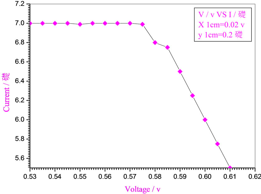
Figure 5. Relation between voltage and current for (Muscovite/ TiO2/Dye/Al) (0.2 w/m2, 0.1 g concentration-600 rpm-300 k).

Figure 6. Relation between voltage and current for (Muscovite/ TiO2/Dye/Al) (0.2 w/m2, 0.2 g concentration-600 rpm-300 k).

Figure 7. Relation between voltage and current for (Muscovite/ TiO2/Dye/Al) (0.2 w/m2, 0.1 g concentration-700 rpm-300 k).

Figure 8. Relation between voltage and current for (Muscovite/ TiO2/Dye/Al) (0.2 w/m2, 0.2 g concentration-700 rpm-300 k).
tween the light intensity I, the solar cell efficiency and fill factor. In details the result of this work can be con-

Figure 9. Relation between voltage and current for (Muscovite/ TiO2/Dye/Al) (0.2 w/m2, 0.1 g concentration-800 rpm-300 k).

Figure 10. Relation between voltage and current for (Muscovite/TiO2/Dye/Al) (0.2 w/m2, 0.2 g concentration-800 rpm-300 k).

Figure 11. Relation between voltage and current for (Muscovite/ TiO2/Dye/Al) (0.4 w/m2, 0.1 g concentration-600 rpm-300 k).
tributed as follows:
At a constant temperature, and rotations per Minuit (of the spin coating instrument), the solar cell efficiency and fill factor, increase with the samples concentration at the same intensity of light 0.2 w/m2, and decrease, when we

Figure 12. Relation between voltage and current for (Muscovite/TiO2/Dye/Al) (0.4 w/m2, 0.2 g concentration-600 rpm-300 k).

Figure 13. Relation between voltage and current for (Muscovite/TiO2/Dye/Al) (0.4 w/m2, 0.1 g concentration-700 rpm-300 k).

Figure 14. Relation between voltage and current for (Muscovite/TiO2/Dye/Al) (0.4 w/m2, 0.2 g concentration-700 rpm-300 k).
increase the light intensity to 0.4 w/m2. This shows that

Figure 15. Relation between voltage and current for (Muscovite/TiO2/Dye/Al) (0.4 w/m2, 0.1 g concentration-800 rpm-300 k).

Figure 16. Relation between voltage and current for (Muscovite/TiO2/Dye/Al) (0.4 w/m2, 0.2 g concentration-800 rpm-300 k).

Table 1. Cell efficiency and fill factor results for different light intensity for (Muscovite/TiO2/dye/Al).

Table 2. Cell efficiency and fill factor results for different light intensity for (Muscovite/TiO2/dye/Al).

Table 3. Cell efficiency and fill factor results for different light intensity for (Muscovite/TiO2/dye/Al).
the intensity of the source negatively affected the solar cell efficiency and fill factor at intensity values greater than 0.2 w/m2, according to the sample studied in this work.
Also one of the most important results noticed, and observed in this paper is that the increasing in rotations per Minuit had to influence the solar cell efficiency, and fill factor.
In a previous work [19], the same result was obtained, but, the intensity was not taken into account, this work insured that the intensity of light played only a secondary role as one of the parameters affecting the solar cell efficiency.
REFERENCES
- Suhas, P.S. (2004) Solar energy principles of thermal collection and storage. Tata McGraw-Hill, New York, 2nd Edition.
- Gary, H.P. and Prakash, J. (2000) Solar energy fundamentals and applications. Tata McGraw-Hill, WYKEHAM Publications, London, 434.
- Schaller, R.D. and Klimov, V.I. (2004) High efficiency carrier multiplication in PbSe Nano crystals: Implications for solar energy conversion. Physical Review Letters, 92, 186601-1-186601-4. http://dx.doi.org/10.1103/PhysRevLett.92.186601
- Paul, D.M. and Edward, N.S. (1981) Photo voltaic sunlight to electricity in one step. Wiley, John & Sons, Incorporated, 224.
- Wolf, M. (1976) Historical development of solar cells. IEEE Press, New York, 274.
- Jasprit, S. (1994) Semiconductor devices-An interduction. MC Graw Hill, New York, 669.
- Mckelvey, J.P. (1982) Solid state and semiconductors physics. Harper and Row, New York.
- Shockley, W. and Queisser, H.J. (1961) Detailed balance limit of efficiency of pn junction solar cells. Journal of Applied Physics, 32, 10. http://dx.doi.org/10.1063/1.1736034
- Hovel, H.J. (2013) Modelling of GaAsP/InGaAs/GaAs strain-balanced multiple-quantum well solar cells. Journal of Applied Physics, 113, 024512. http://dx.doi.org/10.1063/1.4775404.
- Green, M.A. (1977) General solar cell curve factors including the effects of ideality factor, temperature and series resistance. Solid-State Electronics, 20, 265 53, ISBN07506 33654.
- Green Wood, N.N. (2000) An earns show, chemistry of the elements. 2nd Edition, School of Chemistry, University of Leeds, Leeds.
- Earle, M.D. (1942) The electrical conductivity of titanium dioxide. Physical Review, 61, 56-62.
- Guo, W., Porter, J.F., Chan, C.M. and Chan, C.K. (1996) The synthesis of Tio2 photo catalysts by the vapor phase hydrolysis of titanium tetraisopropoxide. Proceeding of the Asian Pacific Chemical Reaction Engineering Forum, Beijing.
- Michael, G. (2001) Photo electrochemical cells. Nature, 15, 338-344.
- Heeger, A.J., MacDiarmid, A.G. and Shirakawa, H. (2000) Conductive polymers. Nobel Prize in Chemistry.
- Journal of the American Chemical Society (2008) Effect of polymer morphology on P3HT-based solid-state dye sensitized solar cells: An ultrafast spectroscopic investigation. Journal of the American Chemical Society, 21, 1367-1375.
- Chemical Materials (2008) Interface modification on TiO2 electrode using dendrimers in dye-sensitized solar cells toshio nakashima, Norifusa Satoh, Ken Albrecht, and Kimihisa Yamamoto. Department of Chemistry, Faculty of Science and Technology, Keio University, Yokohama, 2538-2543.
- Marchant, R.E., Lea, A.S., Andrade, J.D. and Bockenstedt, P. (1992) Interactions of von Wille-brand factor on mica studied by atomic force microscopy. Journal of Colloid and Interface Science, 148, 261-272. Doi:10.1016/0021-9797(92)90135-9.
- Elgani, R.H., Hassan, M.A. and Allah, M. (2013) Effect of doping concentration on the performance of solar cell constructed from (Muscovite/TiO2/Dye/Al). Natural Science, 5, 52-56.