Open Journal of Composite Materials
Vol.07 No.04(2017), Article ID:77986,12 pages
10.4236/ojcm.2017.74012
Identification of Damage Parameters for Intralaminar Damage Modeling in Laminated Composites Considering Transverse Stress Effects
Rehs T. Gerrit1, Shun Kokubo2, Tomohiro Yokozeki2
1Department of Mechanical Engineering, Technische Universität, Darmstadt, Germany
2Department of Aeronautics and Astronautics, The University of Tokyo, Tokyo, Japan

Copyright © 2017 by authors and Scientific Research Publishing Inc.
This work is licensed under the Creative Commons Attribution International License (CC BY 4.0).
http://creativecommons.org/licenses/by/4.0/


Received: June 1, 2017; Accepted: July 24, 2017; Published: July 27, 2017
ABSTRACT
The aim of this study is to develop an appropriate modeling methodology for the simulation of intralaminar damage in laminated composites under complex loadings. The intralaminar damages are modeled by stiffness reduction controlled by thermodynamic forces as defined in continuum damage mechanics model proposed by Ladevèze. The original method neglected transverse stress in elementary plies during the tensile tests of [45/−45]mS laminates, resulting in variations of the identified damage parameters of Ladevèze model. This study compared the identified damage parameters considering transverse stress effects with those based on the original method. The effect of transverse stress in the identification process on the damage modeling is discussed, and it is found that one of damage coupling parameters and the damage master curves significantly depend on consideration of transverse stress effects. Finally, it is demonstrated that experimental stiffness degradation is well simulated by the prediction using the identified parameters considering transverse stress effects.
Keywords:
Composite Laminates, Continuum Damage Mechanics, Thermodynamic Force, Damage Parameters

1. Introduction
Laminated composites are widely used in aerospace and automotive application because of its high specific stiffness and strength. These light-weight characteristics motivated us to apply the composites to their primary structures. Generally, composites exhibit significant anisotropic mechanical behavior as well as complex damage accumulation process (fiber breakage, fiber/matrix interfacial debonding, microcracks, delaminations, etc.) compared to traditional isotropic metal/polymer materials [1] - [10] . As application-related damage tolerance consideration (e.g. foreign object damages, crashing behavior, and fatigue damages) is required for the design of primary structures, it is necessary to develop a sophisticated but tractable damage simulation tool to express the above-mentioned mechanical and damage behavior of composites.
Continuous carbon fiber laminated composites are expected to be good candidates for primary aerospace/automobile structures. Composites consist of reinforced fibers and polymer matrix. Multiscale modeling which can connect microstructures (fibers and matrix, fiber architectures etc.) to overall structures has been actively investigated, and computational cost and complex programs prevent the designers and the engineers from using the precise modelling. Mesoscale modeling (i.e. ply-level homogeneous modeling) using continuum damage mechanics is a cost-efficient and tractable way to simulate complex damage processes in laminated composites for structural design [11] [12] [13] [14] [15] . Large-scale damages (e.g. delaminations) are often modeled by cohesive zone modeling [16] [17] [18] , which can be easily combined with continuum damage mechanics. Therefore, the present paper takes a mesoscale stand, in which intralaminar damages are modeled by continuum damage mechanics and interlaminar damages are simulated by cohesive zone models, for the development of efficient design tool of composite structures. The present study focuses on the intralaminar damage modeling, although interlaminar modeling is also to be incorporated as the future work.
Regarding the continuum damage mechanics of laminated composites, Ladevèze and Le Dantec [11] constructed a continuum damage model for intralaminar mechanical behavior of laminated composite, taking stiffness reduction, fiber elastic nonlinearity, and matrix plasticity into account. This model can describe the brittle fracture of fiber, matrix microcracking and fiber/matrix interfacial debonding as damage parameters. Casari [12] extended the model to three-dimensional woven composite. This study applied Ladevèze model to consider intralaminar damages in laminated composites. In the identification process of the damage parameters as shown in Ladevèze and Le Dantec [11] , [0/90]mS, [45/−45]mS, [67.5/−67.5]mS laminates are used to measure stress-strain responses. During this experimental analysis, the original method neglected transverse stress normal to fiber direction in elementary plies of [45/−45]mS laminates. However, tensile loadings applied to [45/−45]mS laminates induces in-plane transverse stress as well as shear stresses in each ply, both of which are to be taken into account in the identification process of damage coupling parameters. The present study investigates the effect of consideration of transverse stress during the experimental data analysis of [45/−45]mS laminates on the damage parameters of Ladevèze model.
The following sections describe the summary of Ladevèze model and the original experimental identification process of damage parameters, followed by the modified identification process proposed in this study. Experiments for the parameter identification are explained, and the parameters obtained by the original and modified method are presented with discussions on the effect of transverse stress in the identification process on the damage modeling.
2. Intralaminar Damage Modeling
2.1. Ladevèze Model [11]
Basis of the Ladevèze theory is the strain energy function of a damaged ply in a two dimensional formulation, shown in Equation (1):
 (1)
(1)
In this equation, damage parameters, dij, are introduced to relate the elastic modulus to the damage state.  and
and  are initial Young’s modulus and shear modulus, respectively, σij is stress, νij is Poisson’s ratio, and subscripts 1 and 2 represents direction along fiber and transverse to the fiber, respectively. < >+ and < >− are valid when the value is positive and negative, respectively (i.e. += a when a is positive, and + = 0 when a is negative). Note the crack closure under compressive transverse stress is considered. An increase of dij will result in a decrease of the modulus, resulting in the following strain-stress relationship of a damaged ply:
 (2)
(2) (3)
(3)Figure 1 shows the typical relationship between the damage parameters, dij, and the thermodynamic forces, Yij of fiber-reinforced composites. In the fiber direction, d11 reflects the brittle nature of fiber-dominated fractures; d11 is set to be 0 at the initial stage, and a sudden jump to 1 takes place. The transverse and shear damages exhibit progressive accumulation; d22 and d12 are represented as a linear equation, polynomial form or other expressions of the thermodynamic forces. In general, transverse stresses and shear stresses induce matrix damages and fiber/matrix interfacial damages, which in turn results in transverse and

Figure 1. Typical relationships between damage parameters and thermodynamic forces.
 (4)
(4) (5)
(5)2.2. Procedure for Parameter Identification
 (6)
(6) (7)
(7) (8)
(8) (9)
(9)where the following equations hold:
 (10)
(10) (11)
(11)2.3. Effect of Transverse Stress in [45/−45]mS Laminates
 (12)
(12)3.2. Analysis of Experimental Data
Typical stress-strain curves obtained by quasi-static monotonic tensile tests of three laminates are presented in Figure 2. The elastic parameters are then evaluated following the previous study [11] , and summarized in Table 1. Cyclic tensile results of [45/−45]2S, and [67.5/67.5]2S specimens were converted to the stress-strain relationships in the local direction using Equations (8)-(12). A typical in-plane shear stress-shear strain curve obtained by cyclic tests of [45/−45]2S laminates is shown in Figure 3. The black solid lines indicate the apparent shear moduli of damaged laminates, from which we can evaluate the damage parameters d12 (as defined in Equation (2)) as a function of the applied maximum stress (or the corresponding thermodynamic force) during each cycle. The d12-Y12

Figure 2. Stress-strain (σL-εL) curves obtained by quasi-static monotonic tensile tests of three laminates.
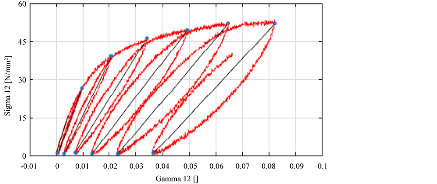
Figure 3. In-plane shear stress-shear strain curve obtained by cyclic tests of [45/−45]2S laminates.
curve obtained from [45/−45]2S laminates is presented in Figure 4. Similarly, other damage curves were obtained based on the cyclic stress-strain curves.
3.3. Evaluation of Damage Master Curve
If we consider Equation (12), Y22 is also taken into account for [45/−45]2S laminates in uniaxial tension. To investigate the transverse stress effects of [45/−45]2S laminates, the following two methods are introduced in the present study. The Case-B includes Y22 when the d12-Y curve is obtained from [45/−45]2S laminates, and coupling parameters are determined based on the three damage curves (d12-Y from [45/−45]2S laminates, d12-Y from [67.5/−67.5]2S laminates, and d22-Y from [67.5/−67.5]2S). The Case-C takes d22 and Y22 from [45/−45]2S laminates into account, and four damage curves (d12-Y from [45/−45]2S laminates, d22-Y from [45/−45]2S, d12-Y from [67.5/−67.5]2S laminates, and d22-Y from [67.5/−67.5]2S) are utilized to identify the coupling parameters and damage master curve. Table 2 summarizes and compares the three cases investigated in the present study when the coupling parameters and the damage master curve are identified.
The damage master curves (d22(=b3d12)-Y) obtained by three methods are presented in Figure 5. The fitted master curves are compared in Figure 6 for

Table 1. Elastic properties of GF/epoxy used in the present study.

Figure 4. d12-Y12 curve obtained by [45/−45]2S laminates.
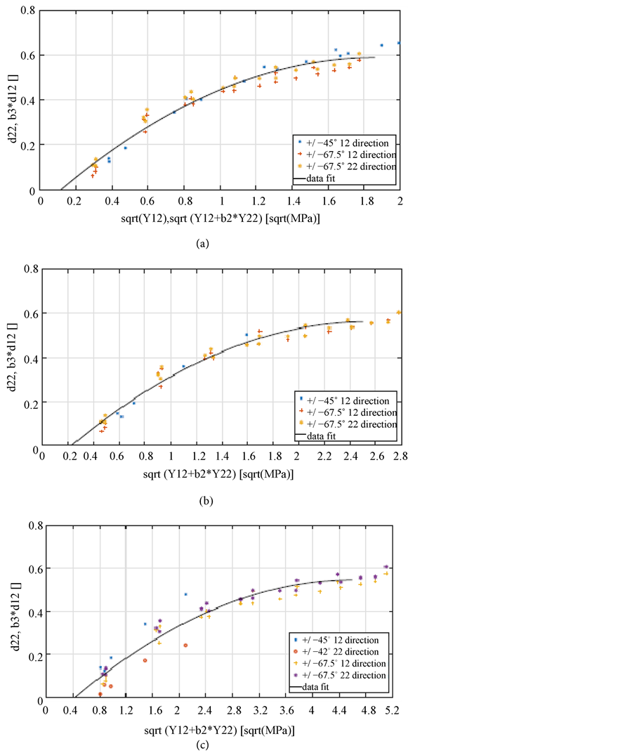
Figure 5. Damage master curves obtained by three methods.
Table 2. Comparison of identification method for coupling parameters and damage master curve.
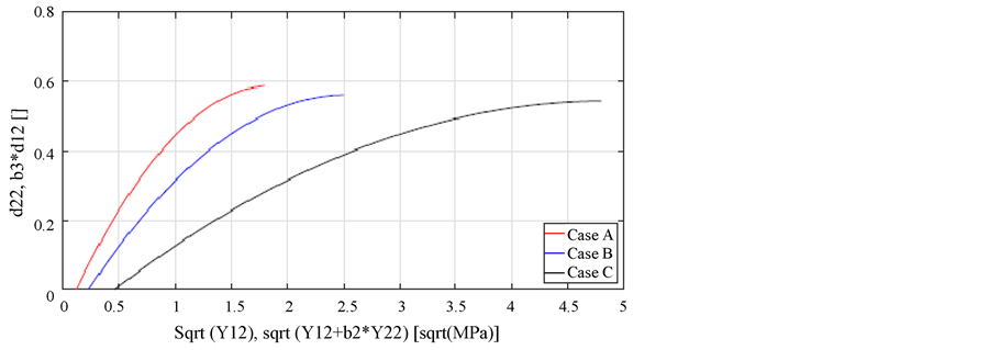
Figure 6. Comparison of damage master curves.
three cases, and expressed as a function of Y, as seen in Table 3. It is confirmed that identified damage master curve based on the experimental data, which is incorporated into the damage simulation, depends on the identification methods as compared in Table 2. This infers the dependency of parameter identification methods on the damage simulation results of laminated composites. It is noted that identified b3 is almost independent of identification methods while b2 depends on the methods. b3 reflects the influence of damages on the reduction of transverse and shear elastic modulus, which should be determined in a damage mechanics sense, and therefore, it does not depend on the consideration of transverse stress effects. On the other hand, b2 accounts for the coupling degree of transverse and shear stresses which drive damage accumulations. It is justified that consideration of transverse stress effects of [45/−45]2S laminates influences the identified values of b2.
Finally, the degradation of longitudinal stiffness (i.e. apparent modulus in loading direction, EL) of [45/−45]2S laminates under uniaxial tensile loading is predicted using the identified damage parameters. Stiffness degradation is plotted as a function of applied stress in Figure 7, compared with experimental results. The predicted curves using Case-B identification (considering transverse stresses of [45/−45]2S laminates) fit well with the experimental results. This demonstrates the importance of consideration of transverse stress of [45/−45]2S laminates during the identification process. It is noted that the prediction based on Case-C identification overestimates the stiffness. This might results from the difficulty in obtaining the d22-Y curve from [45/−45]2S (because d22 in [45/−45]2S specimens is small during the uniaxial tensile loading), and the identified damage curve somewhat loses the accuracy, which is further to be investigated.

Figure 7. Stiffness degradation of [45/−45]2S laminates under uniaxial tensile loadings: comparison between simulated results and experimental results.
Table 3. Estimated coupling parameters and damage curves based on three different methods.
- 1. Garrett, K.W. and Bailey, J.E. (1977) Multiple Transverse Fracture in 90o Cross-Ply Laminates of a Glass Fiber-Reinforced Polyester. Journal of Materials Science, 12, 157-168.
https://doi.org/10.1007/BF00738481 - 2. Joshi, S.P. and Sun, C.T. (1985) Impact Induced Fracture in a Laminated Composite. Journal of Composite Materials, 19, 51-66.
- 3. Kim, R.Y. and Soni, S.R. (1984) Experimental and Analytical Studies on the Onset of Delamination in Laminated Composites. Journal of Composite Materials, 18, 70-80.
- 4. Ogihara, S., Kobayashi, S. and Reifnider, K.L. (2003) Characterization of Nonlinear Behavior of Carbon/Epoxy Unidirectional and Angle-Ply Laminates. Advanced Composite Materials, 11, 239-254.
https://doi.org/10.1163/156855102762506281 - 5. Yokozeki, T., Aoki, T., Ogasawara, T. and Ishikawa, T. (2005) Effects of Layup Angle and Ply Thickness on Matrix Crack Interaction in Contiguous Plies of Composite Laminates. Composites Part A: Applied Science and Manufacturing, 36, 1229-1235.
https://doi.org/10.1016/j.compositesa.2005.02.002 - 6. Yokozeki, T., Ogasawara, T. and Ishikawa, T. (2006) Nonlinear Behavior and Compressive Strength of Unidirectional and Multidirectional Carbon Fiber Composite Laminates. Composites Part A: Applied Science and Manufacturing, 37, 2069-2079.
https://doi.org/10.1016/j.compositesa.2005.12.004 - 7. Yoshimura, A., Yashiro, S., Okabe, T. and Takeda, N. (2007) Characterization of Tensile Damage Progress in Stitched CFRP Laminates. Advanced Composite Materials, 16, 223-244.
https://doi.org/10.1163/156855107781393740 - 8. Prabhakar, P. and Waas, A.M. (2013) Interaction between Kinking and Splitting in the Compressive Failure of Unidirectional Fiber Reinforced Laminated Composites. Composite Structures, 98, 85-92.
https://doi.org/10.1016/j.compstruct.2012.11.005 - 9. Suemasu, H. (2016) Analytical Approaches to Compression after Impact (CAI) Behavior of Carbon Fiber-Reinforced Composite Materials. Advanced Composite Materials, 25, 1-18.
https://doi.org/10.1080/09243046.2015.1122416 - 10. Ueda, M., Kimura, K. and Jeong, T.-K. (2016) In situ Observation of Kink-Band Formation in a Unidirectional Carbon Fiber Reinforced Plastic by X-Ray Computed Tomography Imaging. Advanced Composite Materials, 25, 31-43.
https://doi.org/10.1080/09243046.2014.973173 - 11. Ladeveze, P. and Le Dantec, E. (1992) Damage Modeling of the Elementary Ply for Laminated Composites. Composites Science and Technology, 43, 257-267.
https://doi.org/10.1016/0266-3538(92)90097-M - 12. Casari, P., Ladeveze, P. and Chou, T.W. (1999) Damage Modeling and Characterization of a Three-Dimensional Woven Composite. Proceedings of 12th International Conference on Composite Materials, Paris, 5-9 July 1999, 717.
- 13. Matzenmiller, A., Lubliner, J. and Taylor, R.L. (1995) A Constitutive Model for Anisotropic Damage in Fiber-Composite. Mechanics of Materials, 20, 125-152.
https://doi.org/10.1016/0167-6636(94)00053-0 - 14. Allix, O., Ladeveze, P. and Vittecoq, E. (1994) Modelling and Identification of the Mechanical Behaviour of Composite Laminates in Compression. Composites Science and Technology, 51, 35-42.
https://doi.org/10.1016/0266-3538(94)90154-6 - 15. Lapczyk, I. and Hurtado, J.A. (2007) Progressive Damage Modeling in Fiber-Reinforced Materials. Composites Part A: Applied Science and Manufacturing, 38, 2333-2341.
https://doi.org/10.1016/j.compositesa.2007.01.017 - 16. Geubelle, P.H. and Baylor, J.S. (1998) Impact-Induced Delamination of Composites: A 2D Simulation. Composites Part B: Engineering, 29, 589-602.
https://doi.org/10.1016/S1359-8368(98)00013-4 - 17. Turon, A., Camanho, P.P., Costa, J. and Davila, C.G. (2006) A Damage Model for the Simulation of Delamination in Advanced Composites under Variable-Mode Loading. Mechanics of Materials, 38, 1072-1089.
https://doi.org/10.1016/j.mechmat.2005.10.003 - 18. Li, S., Thouless, M.D., Waas, A.M., Schroeder, J.A. and Zavattieri, P.D. (2005) Use of a Cohesive-Zone Model to Analyze the Fracture of a Fiber-Reinforced Polymer-Matrix Composite. Composites Science and Technology, 65, 537-549.
https://doi.org/10.1016/j.compscitech.2004.08.004