Optics and Photonics Journal
Vol. 3 No. 1 (2013) , Article ID: 29259 , 5 pages DOI:10.4236/opj.2013.31019
The Loss of Optical Fiber with Pure Quartz Core and Fluorine—Doped Glass Cladding
The 46 Institute of China Electronics Science and Technique Group Corporation, Tianjin, China
Email: gym46@yahoo.cn
Received November 12, 2012; revised December 12, 2012; accepted December 20, 2012
Keywords: Optical Fiber; Pure Quartz Core; Large Diameter Core; Cladding with F-Doped Glass; The Optical Fiber of Transmitting Light Energy
ABSTRACT
The optical fiber with pure quartz core and Fluorine-doped glass cladding was made by POD (plasma outside deposition) technique in some corporations, while we used the creative technique of “overcladding F-doped tube onto quartz rod in high temperature” to make the optical fiber which has the same structure as that from POD, in order to research and compare the influence factors on the loss of the fiber, our research work includes contrast experiments on coating polymers with different refractive index and the concentricity error of the fiber core and cladding. The measurement results show us that there are great differences in the loss spectra between the different fiber samples. We made analysis of it.
1. Introduction
The optical fiber with pure quartz core and fluorinedoped glass cladding is a new kind of large core optical fiber that appeared in recent years. Some corporations have made it by POD technique (plasma outside deposition) [1], which decreased the cost of making large core fiber greatly in comparison with that from conventional MCVD technique. The diameter of the preform is greatly increased, and now it has replaced the conventional large core fiber and is widely used in many fields. Through many experiments, at last we made the fiber with the same structure as that from POD by the technique of “overcladding F-doped tube onto the quartz rod in high temperature” [2], i.e. “rod in tube” technique, in which the F-doped tube was fabricated by PCVD (plasma chemical vapor deposition), and the optical fiber preform was made by MCVD (modified chemical vapor deposition). The technique is characterized by simplicity, low cost, high end product efficiency, large ratio of “core diameter/fiber diameter” and the low loss of the optical fiber, etc.
The structure of this kind of fiber is quite different from that made by conventional technique. There are two main different points: one is that the fiber core material is pure quartz, another is that the cladding thickness is greatly reduced. The influence of the first different point on the fiber loss is obvious, and what influence will come about the loss of fibre brought by another different point? We want to be quite clear on this point, make it clear, we conducted a series of researches to confirm that, which include: 1) We cover the fiber with high and low refractive index polymers separately, and compare the changes between their loss spectra; 2) The influence of the glass cladding thickness with low-refractive-index coat on fiber loss spectra; 3) The influence of the concentricity error between core and cladding on the fiber loss spectra. We found the great changes on their loss spectra in the experiments, which shows that the influence of the above factors is obvious.
2. Experiment
2.1. Optical Fiber Making
Before using our technique of “rod in tube” to make the optical fiber with pure quartz core and F-doped glass cladding, we have to get firstly the F-doped tube treated by a special process, in order to avoid bubble appearing on the surface of F-doped tube in the following high temperature process. Then we use the “rod in tube” technic to make the fiber preform in high temperature on MCVD lathe, as shown in Figure 1, next we grind the surface quartz material of the preform down and reveal the F-doped glass layer of the substrate tube, thus making the preform of the same structure as that from POD technique and drawing it into the fiber [3].
2.2. Contrast Experiments on Different Polymer Coat Materials
In the experiments, we made two optical fiber preforms No. 1 and No. 2 by the technique of “rod in tube” and mechanical grinding. We used the quartz rod (type F300ES) as the core of two preforms. The F-doped quartz tubes have the same parameters. We made two optical fibers 1# and 2# by drawing No. 1 preform two times, whose inner polymer coats have separately low and high refractive index. We also drew No. 2 preform and fabricated the 3# optical fiber, and cover it with high refractive index polymer as inner coat of the fiber. The geometry parameters of 1# and 2# fibers are exactly the same. The design geometry parameters of 3# fiber is the same as them. The detailed materials and the parameters as well as the structure of the optical fibers are shown in Table 1.
3. Results of Experiments
1# and 2# optical fibers were covered respectively with low and high refractive index polymers as the inner coat. Their structure and refractive index distribution are respectively shown in Figures 2 and 3, and their loss spectras are shown in Figures 4 and 5.
The structure and refractive index distribution of 3# optical fiber is shown in Figure 3, and its loss spectra is shown in Figure 6.
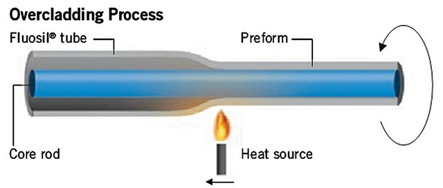
Figure 1. Overcladding F-doped tube onto quartz rod in high temperature.
4. Discussion
4.1. Influence of the Inner Polymer Coat of the Fiber
In Figure 4, because the inner polymer coat of the 1# fiber has the low refractive index, the transmission light reaches and goes through the interface of the core and the F-doped glass cladding is reflected respectively back to the fiber core again by the glass cladding and interface of the inner polymer coat with low refractive index, and it continues to transmit in the fiber [4]. As a result, the transmission loss of 1# fiber can be relatively low. But the situation shown in Figure 5 is quite different, in which the fiber 2# is covered with the high refractive index polymer as inner coat, so the light energy is absorbed by the polymer coat material as it gets out of the core and reaches the interface between the F-doped glass cladding and polymer coat [5], thus resulting in a relatively high background loss of 2# fiber [6]. It’s the reason that leads to the different background loss between the above two fibers.
4.2. Influence of F-Doped Glass Cladding Wall Thickness
In the Figure 5, the loss of 2# fiber is rapidly increased when the wavelength exceeds operation wavelength λ0 (0.808 µm). However, as wavelength exceeds critical wavelength λ2 (1.07 µm), the loss spectra presents a vibration character and keeps essentially a constant value. It means that the loss has nothing to do with wavelength.
As to multimode optical fiber, we know the light with operation wavelength λ0 is effectively limited and transmitted in the fiber waveguide with low loss when the cladding wall thickness with low refractive index is over 3λ0. When the wavelength of the light that transfers in the optical fiber increases, according to relationship of 3λ, in order to keep the light transmitting with low loss in the fiber, it demands the thicker glass cladding wall.
Table 1. Materials and the parameters and the structure of the preform and its optical fiber.


Figure 2. 1# fiber structure with low refractive index polymer as inner coat.

Figure 3. 2# and 3# fiber structure with high refractive index polymer as inner coat.
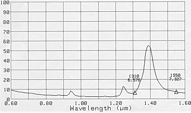
Figure 4. The loss spectra of 1# optical fiber.

Figure 5. The loss spectra of 2# optical fiber.
Through analysis, we think the loss spectra of optical fiber 2# in Figure 5 is the typical one of the fiber with pure quartz core and F-doped glass cladding. Though the cladding wall thickness of the fiber we designed is (110 µm − 100 µm)/2 = 5 µm, which has low refractive index,
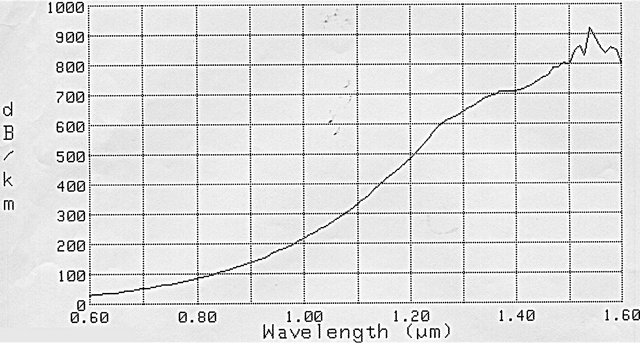
Figure 6. The loss spectra of 3# optical fiber.
but because of the process error of mechanical grinding and fluctuation of fiber diameter, the practical result is that some cladding wall thickness of fiber 2# is less than 5µm. We can see the result from the loss spectra in Figure 5, when the wavelength of light exceeded λ2 = 1.07 µm, the loss of the fiber would reach the highest value and presents a vibration character. It means the light transmitted in the fiber can not be controlled by the glass cladding. Currently, 3λ2 = 3 × 1.07 = 3.21 µm, so we know that the practical cladding wall thickness of the fiber 2# is 3.21 µm. In the opinion above, all the light has same significance when operation wavelength is over 1.07 µm. It will all leak out of the fiber as the leaking modules and absorbed and exhausted by the coating polymer with high refractive index, so the fiber loss opposite to long wavelength (over 1.07 µm) remains essentially a constant value in Figure 5. The loss has nothing to do with wavelength.
4.3. Infiuence of the Concentricity Error of the Fiber Core and Cladding
The loss spectra of 3# optical fiber in Figure 6 is obviously different from that in Figure 5 though they were all covered with high refractive index polymer as inner coat. Besides the larger background loss of the fiber 3#, the fiber loss increases gradually with the increasing of the wavelength. The loss spectra will present vibration when wavelength is over λ3 (1.5 µm).
Through analysis, we think the unusual loss spectra of the 3# fiber has something to do with the tolerance of the F-doped glass cladding wall thickness (concentricity error), which resulted from the mechanical grinding process, as is shown in Figure 7. The minimum wall thickness is δ1, and the maximum wall thickness is δ2 = 1.5 µm (critical wavelength) × 3 = 4.5 µm. Because the loss of 3# fiber is even larger than that of fiber 2# at operation wavelength 0.808 µm, it means that the error of cladding wall thickness leads to the wall thickness around δ1 thinner than 3λ0 = 3 × 0.808 = 2.424 µm, demonstrating that the light has leaked out of the fiber at the wavelength, whereas the cladding wall thickness of the other part of
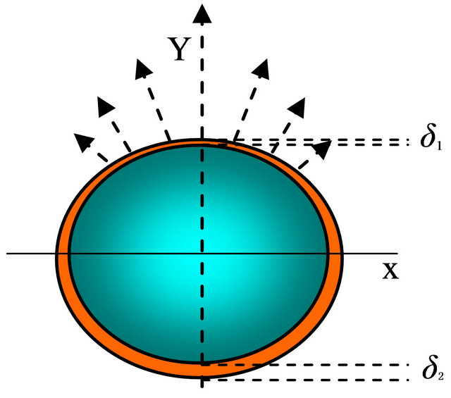
Figure 7. The structure of 3# optical fiber and the light leaking from the aero around δ1.
the fiber is over 3λ0 = 2.424 µm, from Figure 7 we can see that the farther from δ1, the thicker of the cladding wall thickness will be on the fiber section.
As to meridian or precession light, the fiber with large concentricity error results in the result that the light transmitted in the fiber reaches to the aero nearby δ1 leaks out of the fiber and gets into the polymer coat with high refractive index, and it is absorbed and exhausted. This happens already in the range of short wavelength, so the background loss is raised up in the spectra of 3# fiber in Figure 6. Because of the large concentricity error offset structure of the fiber between its core and cladding, with increasing of the wavelength, there are more and more light leaks out of the fiber as leaking modules, which means the glass cladding controlling ability on the transmiting light is weaker and weaker. The geometric aero where the light is leaked out of the fiber became larger and larger, which is around δ1, the leaking light of high grade modules is absorbed and exhausted by polymer coat of high refractive index, and this finally leads to the fiber loss increasing larger and larger with the wavelength of light changing longer and longer. When wavelength λ is over λ3 and 3λ > 3λ3 = δ2, the glass cladding with low refractive index losed any controlling ability about the light which wavelength is over the critical point λ3. All transmitting light in the fiber changes into leaking light and absorbed and exhausted by the inner coating polymer, so the loss is not increased with the increasing of the wavelength. From Figure 6 we can see that the loss spectra of fiber 3# appeared vibration character which is similar with that of 2# fiber in Figure 5, when the wavelength increased longer enough.
5. Conclusions
We know the light propagation constant  , which transmits in the fiber, where n1 is refractive index of the fiber core, λ is the working wavelength, θ is the angle between vector k and the axis of the fiber, and each β is corresponding to one transmitting light module. With increase of the light wavelength λ that transmits in the fiber, β corresponding to each λ will become smaller and smaller. In terms of optics waveguide theory, when the propagation constant β of one transmitting light module reduces and exceeds one critical value β1 (i.e. optical wavelength λ increases and exceeds some value λ1), the transmitting module of light changes into leaking module, if optical wavelength further increases when the propagation constant β of one transmitting light module reduces and exceeds another critical value β2 (i.e. optical wavelength λ increases and exceeds some value λ2), the transmitting light will change its leaking module into radiation module, and lose all transmitting optical energy. This is the relationship between various transmitting optical wavelengths in the fiber and the energy carried by the corresponding module.
Through our experiment results, we can see it is still existed that relationship between the transmitting light wavelength λ and the energy carried by the corresponding module in this kind of fiber, and that because various inner polymer coat and the different glass cladding thickness and the concentricity error between the fiber core and cladding, the relationship is changed more complicated. But from another point, this maybe give us a chance, we can effectively influence the character of the fiber through adjusting some design on it. This provides us with some chances about the potential application of the special fiber.
In addition, from the experiments and discussion above, we have known that the loss of the fiber with pure quartz core and F-doped glass cladding is influenced by many factors, some of which come from the special structure of the fiber, so when someone plans to fabricate this kind of fiber by our technique of “rod in tube”, he should propose the corresponding requests on materials and fiber structure and processing geometry accuracy so that he can ensure the quality of this kind of optical fiber.
REFERENCES
- A. S. Biriukov, E. M. Dianov, K. M. Golant, et al., “Synthesis of Fluorine-Doped Silica Glass by Means of an Outside Deposition Technique Using a Microwave Plasma Torch,” Soviet Lightwave Communications, Vol. 3, No. 1, 1993, pp. 1-12.
- Y. M. Gao, G. Feng, Y. J. Liu, et al., “Optical Fiber with Pure Quartz Core and Fluorine-Doped Glass Cladding,” 14th Opticalfiber Communication & 15th Integrated Optics Science Meeting, Tianjin, 26-30 October 2009.
- Y. M. Gao, G. Feng, Y. J. Liu, et al., “New Technic to Make Optical Fiber with Large Core,” Laser & Infrared, Vol. 41, 2011, p. 447.
- Y. M. Gao, G. Feng, Y. J. Liu, et al., “Numerical Aperture of Optical Fiber with Pure Quartz Core and Fluorine-Doped Glass Cladding,” Laser & Infrared, Vol. 41, No. 2, 2011, p. 169.
- M. Chomat, J. Mrazek, V. Matejec, et al., “Investigation of the Sensitivity of PCS Fibers to Changes of Light Absorption Coefficient of the Cladding,” Proceedings of the SPIE, Vol. 5036, 2003, pp. 72-77. doi:10.1117/12.498249
- J. H. Lee, S. J. Kwak, J. W. Yoon, K. B. Min, M. J. Kim, S. H. Kim and S. K. Oh, “A Study of Polymer Clad Resin with Higher Modules for High NA Fiber,” SPIE, 2008.