Open Journal of Fluid Dynamics
Vol.07 No.03(2017), Article ID:79371,13 pages
10.4236/ojfd.2017.73027
Simulation of Heat Transfer in a Tubular Pipe Using Different Twisted Tape Inserts
Md. Moniruzzaman Bhuyan1, Ujjwal K. Deb2*, M. Shahriar3, Simul Acherjee4
1Department Electrical & Electronics Engineering, Southern University Bangladesh, Chittagong, Bangladesh
2Department of Mathematics, Chittagong University of Engineering & Technology, Chittagong, Bangladesh
3Department of Mechanical Engineering, Chittagong University of Engineering & Technology, Chittagong, Bangladesh
4Department of Mathematics, Narangiri Govt. High School, Chittagong, Bangladesh

Copyright © 2017 by authors and Scientific Research Publishing Inc.
This work is licensed under the Creative Commons Attribution International License (CC BY 4.0).
http://creativecommons.org/licenses/by/4.0/


Received: August 7, 2017; Accepted: September 25, 2017; Published: September 28, 2017
ABSTRACT
This paper performs a simulation study of the heat transfer phenomena in a tubular U-loop pipe. We have investigated the enhancement of heat transfer with mass flow in a pipe without insert, with full length and short length twisted tape inserts. The length of the pipe is approximately 2436.80 mm long with 29 mm inner and 33 mm outer diameter respectively. A constant heat flux is taken which generated the boundary layer of the pipe close to the flowing fluid around the boundary. The simulations are considered for the stationary and the time dependent module for 35 seconds with different length of inserts. The comparisons are made among the results. We observed that the transfer of heat is enhanced significantly with the increase of the length of inserts inside the computational domain. We also found that, full length twisted tape inserts are more effective than comparing with the short length inserts and without insert.
Keywords:
Heat Transfer, Non-Isothermal Flow, Tubular Pipe, Twisted Tape Inserts, Simulation

1. Introduction
The enhancement of heat transfer is the method of developing the performance of heat transfer device. There exist two methods to improve the enhancement of heat transfer. One is active method and another is passive. Both of them are used for augmentation of laminar flow heat transfer [1] [2] . Till now, large number of attempts has been made to reduce the size and costs of the heat exchangers. The heat transfer augmentation techniques play a vital role for laminar flow since the heat transfer coefficient is normally low in plain tubes [3] [4] . The swirl flow devices form an important group of passive augmentation methods where twisted tape is one of the most important members of this group [5] . Pipes with twisted tape inserts have been widely used in heat transfer technology to the heat exchanger applications such as air-conditioning, refrigeration, automobiles, petrochemical industries, solar water heaters, shell and tube heat exchangers, chemical reactors power plant, process industries etc.
In the year 1896, Whitham studied about the twisted tape inserts in fire tubes of stream boilers and their effects in the flow dynamics and heat got an expected satisfactory result [6] . Kidd and Klepper, four decades ago, studied twisted tape and recommended that short length twisted tapes is more feasible for a gas cooled nuclear reactor compared with full length twisted tape [7] [8] . S. K. Saha and his research group investigated heat transfer and pressure drop phenomenon for a laminar flow using twisted tape inserts and mentioned that regularly spaced twisted tape inserts shown better performance than full length twisted tape inserts for high Reynolds numbers [9] . Date and Gaintonde studied about the laminar flow in a tube using twisted tape regularly spaced inserts and predicting characteristics of flow dynamics [10] . P. Promvonge, S. Eiamsa-ard et al. in the year 2007, experimented in a heat transfer augmentation in a circular tube using V-nozzle turbulator inserts and snail entry getting a significant change of heat transfer rate. They suggested that the v-nozzle turbulator inserts gives better results than that of other turbulator devices [11] . In the year 2009, S. Eiamsa-ard et al. investigated on short length twisted tape inserts and showed that it enhances the heat transfer rate with respect to some parameters [12] .
In the year 2009, Rahimi et al. reported computational and experimental investigation of the three modified twisted tapes (perforated, notched and jagged tape) and suggested that this jagged twisted tape gives higher thermal performance comparing to the other two types [13] . In the year 2010, Eiamsa-ard et al. studied that the effects of non-uniform wire coil and twisted tape inserts is more suitable than other methods [14] . In the same year, they also suggested that Delta Winglet Twisted (DWT) tape inserts is more effective than the other typical twisted tape insert and DWT reduces the size of the heat exchanger [15] . Chowdhuri et al. conducted by means of rod pin inserts and got some positive results with respect to keeping constant some parameters [16] . In the year 2012, A.W. Fan et al. reported on the numerical simulation in a circular tube fitted with louvered strip inserts and found that it is easy to fabricate and can be widely used in the heat transfer exchanger technology [17] . In the year 2013, Bodius Salam et al., experimentally investigated heat transfer in a circular tube using rectangular cut twisted tape insert and increased the performance 38% to 80% compare to the smooth tube [18] . Recently, Sabbir et al., numerically showed that the non-isothermal laminar flow in a circular tube using rectangular inserts and found that it is better than that of smooth circular tube [19] [20] . In our very recent paper, we have simulated a heat transfer model using rectangular inserts and increased the heat transfer rate than the plain tube [21] .
In the above discussion we have found that numerous studies are performed about the heat transfer enhancement through the circular tube with different geometrical configurations for laminar flow. However, none of the studies report about the heat transfer augmentation and pressure drop in the tubular pipe with different twisted tape inserts. A non-isothermal flow form is well selected for the simulation. The important effort to utilize different methods is to increase the heat transfer rate by using different kinds of inserts. In the intervening time, it is established that, this way can diminish the manufacturing cost and save up the energy.
In this paper, our main goal is to present the heat transfer phenomena in a circular pipe using inserts by the Finite Element Method. The Finite Element Method (FEM)-based software COMSOL Multiphysics 4.2a version is used for this numerical study [22] . The Finite Element Method gives the more accurate results comparing with the other conventional methods. The technique developed in heat transfer technology by using the FEM software has becomes popular in recent years. In the case of laminar flow heat transfer by conduction, convection and molecular diffusion is important since there is no cross-mixing of fluids. A small amount of heat is transferred by the fluid in the laminar flow. In this simulation, we have observed a procedure of the heat transfer enhancement in a U-loop circular tube by using different twisted tape inserts inside the tube. The water is taken as fluid domain and the pipe domain is made of copper material to rationalize this simulation. A constant heat flux is considered at the surface of the tube.
The rest of the paper is prepared as follows: In Section 2, mathematical model is presented while governing equations of heat transfer flow in Section 3; Boundary conditions for the domain is given in Section 4; Computational domain and the mesh design of the domain are presented in Section 5; In Section 6, numerical results for the heat transfer phenomena is shown followed by conclusion in Section 7.
2. Mathematical Modeling
The aim of this study is to get better performance of the enhancement of heat transfer in a tubular U-loop pipe using different twisted tape inserts. Our model has been conscious as the geometry forms across the flow which enhances the heat transfer. The purpose of using inserts in our model is to increase layer to layer friction and presence of the inserts promotes enhanced heat transfer due to mixing.
3. Governing Equation
In this model we consider the heat transfer phenomena from side to side a U-loop tubular pipe. Thus we have preferred the physics, as non-isothermal laminar flow. In this physics heat flows by conduction, convection via flowing fluid it can be referred as both transportation of heat and mass. The governing equations which describe the flows are the Continuity equation and the Navier-Stokes equations given below:
(1)
(2)
It also solves the heat transfer through a fluid and governed by the following equation:
(3)
where,
(4)
And Q contains heat source other than viscous heating (SI unit: W/m3). For obtaining the heat transfer term used Fourier law of heat conduction, the convective heat flux; q is proportional to the temperature gradient.
(5)
where K is the thermal conductivity can be an isotropic and K becomes a tensor. The convective heat flux is given by
The term represents viscous heating of a fluid can be written on the following form:
The term represents a pressure work is responsible
for the heating of a fluid under adiabatic compression and for some thermo acoustic effects. By using the Equations (3) and (4) we can find
(6)
If the velocity is to zero the equation becomes
(7)
Convective heat transfer coefficient is obtain from
(8)
where Tw and Tb are the wall and bulk temperature, where
Nusselt number is calculated by
(9)
D is the diameter of the tube.
Thermal performance is calculated as
(10)
where η is the thermal performance and hs, hp and hf are the heat transfer for short length, plain tube and full length inserts heat transfer coefficient respectively.
4. Boundary Condition
In the study, the boundary conditions are assumed an uniform velocity i.e. at the inlet, and the temperature of the fluid is , the no slip condition i.e. u = 0 at the inner wall of the tube and the laminar outflow at the outlet of the domain governed by the following equation:
(11)
5. Computational Domain and Meshes
A design of computational domain without insert, with short length twisted tape inserts and full length twisted tape inserts are shown in Figures 1(a)-(e). In our simulation we have considered a typical U-loop circular tube whose length is 2436.80 mm, inner diameter 29 mm, outer diameter 33 mm. To reach a satisfactory computational exactness we continually change the mesh design until the outcomes obtained. The Mesh element becomes higher near the inserts positions have shown in Figures 2(a)-(c). A comparison of mesh design among different insert combinations has shown in the Table 1 and Table 2. The Table 3 showed the temperature variation of different mesh element while Table 4 showed the different parameter values of water in our simulation. As our domain length is large thus computer processor capacity becomes a significant issue for the computational study. The finer mesh is used along the whole computational model for numerical simulation. We used 16 GB DDR3 RAM, Intel core i7 processor based computer for our simulation.
6. Numerical Results and Discussions
The main intention of our study is to ensure the enhancement of heat transfer phenomenon in a U-loop tubular pipe for a non-isothermal laminar flow. The total time taken for the simulation was 35 seconds in the time dependent study. For this investigation the tube thickness is neglected and the boundary conditions for the tube are being measured a uniform heat flux adjoining the water domain layer. As we have only given attention on improving the heat transfer

Figure 1. The computational domain: (a) without insert; (b) with short length twisted tape insert; (c) short length twisted tape insert; (d) with full length twisted tape inserts; (e) full length twisted tape inserts.
rate by considering the flowing fluid thus we ignored the flow heat in the solid tube.
To realize the effect of inserts in to the heat transfer phenomenon, we carried out the simulations by varying the twisted tape inserts. The temperature distributions plot for water domain with move view has shown in Figure 3(a). The legends with each figure characterize the temperature distributions of water at singular time positions of the computational domain. As higher heat flux is taken at the boundary layer, hence we observed large change of the temperature at the outlet. We able to see almost uniform temperature distribution for without insert combination. However after using inserts non-uniform temperature distributions are observed which is shown in Figure 3(b) and Figure 3(c) respectively.
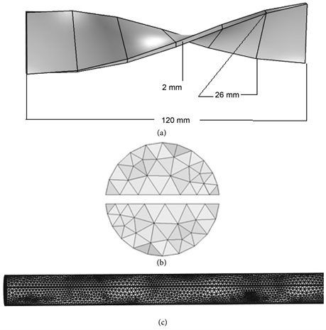
Figure 2. The computational domain: (a) short length twisted tape insert; (b) cross-section of mesh design; (c) mesh design of domain with inserts.

Table 1. Mesh elements comparison of a tubular U-loop pipe with different combination of inserts.
To investigate the results we put the initial temperature at the inlet 293.15 k. From our simulation we observed that the outlet temperature is 368.63 k for without insert, for the short length twisted tape inserts we found outlet temperature is 496.01 k which is better than the without insert. Finally we observed for the full length inserts and found the outlet temperature is 502.47 k. We can conclude that, the full length inserts done better than the other two types of inserts.
Table 2. Extra fine Mesh elements comparison of a tubular U-loop pipe with different combination of inserts.
Table 3. Temperature comparison of a tubular U-loop pipe with different combination of inserts.
Table 4. Parameters value for the simulation.
Figures 3(a)-(c) describe the above temperature.
In the position of 500 mm, The fluid temperatures are found the without insert after 15 sec, 25 sec, 35 sec are 333.6 k, 348.45 k, and 357.43 k respectively. Again for the short length twisted tape inserts and full length twisted tape inserts temperature after 15 sec, 25 sec, and 35 sec are 403.14 k, 426.63 k, and 443.26 k, for short length twisted tape inserts 412.6 k, 440.38 k, and 458.44 k respectively for full length twisted tape inserts. It is very clear that, full length twisted tape inserts gives better heat transfer rate compare with the other design which are shown in the Figures 4(a)-(c) for without insert Figures 4(d)-(f) for short length twisted tape inserts and Figures 4(g)-(i) for full length twisted tape inserts respectively. Again, in the position of 500 mm, changing the mesh design

Figure 3. The computational domain of surface temperature of (a) without insert, (b) short length twisted tape inserts, and (c) full length twisted tape inserts.
we found the temperatures for without insert after 15 sec, 25 sec, 35 sec are respectively 344.92 k, 366.52 k, 379.52 k and for the short length twisted tape inserts and full length twisted tape inserts temperature after 15 sec, 25 sec, 35 sec are 415.24 k, 474.08 k, 504.66 k for the short length twisted tape inserts 429.76 k, 513.19 k, 539.68 k for the full length twisted tape inserts. This is shown in the Figures 5(a)-(c) for without insert Figures 5(d)-(f) for short length twisted tape inserts and Figures 5(g)-(i) for full length twisted tape inserts respectively. The Figure 6 represents the effect of Nusselt number due to the different form of inserts. We observed that full length inserts gives the higher Nusselt number compare to the other two types of inserts. From Figure 7, we found that thermal performance above unity indicates that the effect of heat transfer enhancement due to the full length twisted inserts is more dominant than the short length twisted tape inserts.
7. Conclusion
A computational study of heat transfer phenomenon of a fluid flow through a tubular pipe with inserts and without insert for a non-isothermal laminar flow has been studied. A typical U-loop circular tube with inserts and without insert is considered for our simulation. The working fluid is considered as water in our study and the initial temperature is assumed at the inlet is 293.15 k. The total time taken for the simulation was 35 seconds in the time-dependent study. The temperature distributions at the inserts position have been described. In this investigation, we found that the tube with inserts enhanced significant amount of heat than the without insert. Moreover, the full length twisted tape inserts gives the better results than the short length twisted tape inserts and without insert.

Figure 4. Temperature variations of (a)-(c) without insert, (d)-(f) short length twisted tape inserts, and (g)-(i) full length twisted tape inserts.

Figure 5. Temperature variations of (a)-(c) without insert, (d)-(f) short length twisted tape inserts, and (g)-(i) full length twisted tape inserts.

Figure 6. Relation among different insert and Nusselt Number (Nu).

Figure 7. Thermal performance of short length and full length twisted tape inserts.
Acknowledgements
The authors gratefully acknowledge the technical supports provided by the Centre of Excellence in Mathematics, Department of Mathematics, Mahidol University, Bangkok 10400, Thailand.
Cite this paper
Bhuyan, M.M., Deb, U.K., Shahriar, M. and Acherjee, S. (2017) Simulation of Heat Transfer in a Tubular Pipe Using Different Twisted Tape Inserts. Open Journal of Fluid Dynamics, 7, 397-409. https://doi.org/10.4236/ojfd.2017.73027
References
- 1. Bergles, A.E. and Rosenow, W.M. (1985) Techniques to Augment Heat Transfer Reading: Handbook of Heat Transfer Applications. McGraw-Hill, New York.
- 2. Bergles, A.E. and Webb, R.L. (1985) A Guide to the Literature on Convective heat Transfer Augmentation. Advance Enhanced Heat Transfer, 43, 81-89.
- 3. Hutton, D.V. (2004) Fundamental of Finite Element Analysis. McGraw Hill Companies, New York.
- 4. Cengel, Y.A. (2006) Heat and Mass Transfer. 5th edition, McGraw Hill, New York.
- 5. Eiamsa-ard, S. and Promvonge, P. (2005) Enhancement of Heat Transfer in a Tube with Regularly-Spaced Helical Tape Swirl Generators. Solar Energy, 78, 483-494.
- 6. Whitham, J.M. (1896) The Effects of Retarders in Fire Tubes of Stream Boilers. Street Railway, 12, 374.
- 7. Kidd Jr, G.C. (1969) Heat Transfer and Pressure Drop for Nitrogen Flowing in Tubes Containing Twisted Tapes. AIChE Journal, 15, 581-585. https://doi.org/10.1002/aic.690150420
- 8. Klepper, O.H. (1972) Heat Transfer Performance of Short Twisted Tapes. AIChE Journal, 35, 1-24. https://doi.org/10.2172/4645882
- 9. Saha, S.K., Gaitonde, U.N. and Date, A.W. (1989) Heat Transfer and Pressure Drop Characteristics of Laminar Flow in a Circular Tube Fitted with Regularly Spaced Twisted Tape Elements. Experimental Thermal Fluid Science, 2, 310-322.
- 10. Date, A.W. and Gaintonde, U.N. (1990) Development of Correlations for Predicting Characteristics of Laminar Flow in a Tube Fitted with Regularly Spaced Twisted Tape Elements. Experimental Thermal Fluids Science, 3, 373-382.
- 11. Eiamsa-ard, S., Woncharee, K., Eiamsa-ard, P. and Thianpong, C. (2007) Heat Transfer Enhancement in a Tube Using V-Nozzle Turbulator Inserts and Snail Entry. Experimental Thermal and Fluid Science, 32, 332-340.
- 12. Eiamsa-ard, S., Thianpong, C. and Eiamsa-ard, P. (2009) Convective Heat Transfer in a Circular Tube with Short Length Twisted Tape Insert. International Communication in Heat and Mass Transfer, 36, 363-371. https://doi.org/10.1016/j.icheatmasstransfer.2009.01.006
- 13. Rahimi, M., Shabanian, S.R. and Alsairafi, A.A. (2009) Experimental and CFD Studies on Heat Transfer and Friction Factor Characteristics of a Tube Equipped with Modified Twisted Tape Inserts. Chemical Engineering Process, 48, 762-770. https://doi.org/10.1016/j.cep.2008.09.007
- 14. Eiamsa-ard, S., Nivesrangsan, P., Promvonge, P. and Chokphoemphun, S. (2010) Influence of Combined Non-Uniform Wire Coil and Twisted Tape Inserts on Thermal Performance Characteristics. International Communication Heat and Mass Transfer, 37, 850-856. https://doi.org/10.1016/j.icheatmasstransfer.2010.05.012
- 15. Eiamsa-ard, S., Woncharee, K., Eiamsa-ard, P. and Thianpong, C. (2010) Heat Transfer Enhancement in a Tube Using Delta-Winglet Twisted Tape Inserts. Applied Thermal Engineering, 30, 310-318. https://doi.org/10.1016/j.applthermaleng.2009.09.006
- 16. Chowdhuri, M.A.K., Hossain, R.A. and Sarkar, M.A.R. (2011) An Experimental Investigation of Turbulent Flow Heat Transfer through Tube with Rod-Pin Insert. International Journal of Engineering, Science and Technology, 3, 76-81.
- 17. Fan1, A.W., Deng, J.J., Nakayoma, A. and Liu, W. (2012) Parametric Study on Turbulent Heat and Characteristics in a Circular Tube Fitted with Louvered Strip Inserts. International Journal of Heat and Mass Transfer, 55, 5205-5213. https://doi.org/10.1016/j.ijheatmasstransfer.2012.05.023
- 18. Salam, B., Biswas, S., Saha, S. and Bhuiya, M.M.K. (2013) Heat Transfer Enhancement in a Tube Using Rectangular Cut Twisted Tape Insert. Procedia Engineering, 56, 96-103. https://doi.org/10.1016/j.proeng.2013.03.094
- 19. Hossain, S., Deb, U.K. and Rahman, K.A. (2015) Numerical Simulation of the Heat Transfer Phenomenon for a Fluid in a Circular Tube without Insert and with Inserts. International Journal of Integrated Science and Technology, 1, 53-57.
- 20. Hossain, S., Deb, U.K. and Rahman, K.A. (2015) The Enhancement of Heat Transfer in a Circular Tube with Insert and without Insert by Using the Finite Element Method. Procedia Engineering, 105, 81-88. https://doi.org/10.1016/j.proeng.2015.05.010
- 21. Bhuyan, M.M., Deb, U.K., Shahriar, M. and Acherjee, S. (2017) Simulation of Heat Transfer in a Tubular U-Loop Pipe Using the Rectangular Inserts and without Insert. AIP Conference Proceedings, 1851, 020011. https://doi.org/10.1063/1.4984640
- 22. Comsol Multiphysics Versions 4.2a. http://www.comsol.com