Circuits and Systems
Vol.07 No.13(2016), Article ID:72126,14 pages
10.4236/cs.2016.713346
Centralized Solar PV Systems for Static Loads Using Constant Voltage Control Method
S. Alagammal, Dr. N. Rathina Prabha, I. Aarthy
Department of Electrical & Electronics Engineering, Mepco Schlenk Engineering College, Sivakasi, India

Copyright © 2016 by authors and Scientific Research Publishing Inc.
This work is licensed under the Creative Commons Attribution International License (CC BY 4.0).
http://creativecommons.org/licenses/by/4.0/


Received: May 6, 2016; Accepted: May 17, 2016; Published: November 21, 2016
ABSTRACT
The alternative energy resources, like solar, are always complementary due to environmental changes. Energy generation with the sources such as solar and wind is gaining importance and of that photovoltaic conversion is the main focus of researches due to its promising potential as the electrical source. This paper presents the constant voltage method of control where the output of the converter is maintained constant irrespective of the variations in the irradiance with the high step-up isolated efficient single switch DC-DC converter for the solar PV systems. Constant voltage method of control uses the array of photovoltaic systems as its energy source. The output of the Solar PV systems is nonlinear and has its dependency on temperature and irradiance by which the panel voltage and current varies with the variation in irradiance. Constant voltage control method always operates in such a way that the converter voltage is tried to be maintained constantly to the reference voltage which is set by the user. The system used here utilizes high step single switch isolated DC-DC converter and monitors the voltage continuously by varying the duty cycle to maintain the converter voltage always constant. As a way of improving the performance, both the open and closed loop analysis is done where the closed loop analysis uses the PI controller for its performance. The model is implemented in MATLAB and it accepts the irradiance as the input and outputs the constant voltage from the converter and the feasibility of the proposed converter topology is confirmed with experimental results of the prototype model.
Keywords:
Photovoltaic System, Centralized System, Constant Voltage Control Method, Proportional-Integral Controller

1. Introduction
Multi-output DC-DC converters have become very popular recently and they are particularly used in many portable and handheld consumer applications. Portable devices use sub-modules which have different voltage requirements. Their small-size and light- weight make them very attractive and the cost is also optimized. Traditionally, isolated transformer-based multi-output DC-DC converters were widely employed to provide multiple output voltages. However, they are relatively bulky due to the presence of the reactive components. There is a single maximum power point in the I-V and P-V characteristics of the solar PV systems and it is the point where the panel can deliver the maximum power [1] [2] [3] . This point can vary with respect to the irradiance and the temperature by which the variation in panel voltage and current also varies. As the sun varies its position continuously by its movement, the irradiance falling on the panel varies following this. The voltage and the current of the panel vary as the irradiance fluctuates. Here the constant voltage method of calculation is not the method of mechanical movement which moves the panel according to the suns movement. MPPT is an electronic method of tracking where the operating point is adjusted to always extract the maximum power [4] . In the same way, the duty cycle of the converter is adjusted by the constant voltage control method in order to maintain the converter voltage constant. This paper proposes the constant voltage method where the output of the converter is always tried to maintain constant. The conventional DC-DC boost converters cannot provide the high step-up ratio due to the losses associated with the power switches and diodes. Moreover, the boost converter can give the high step-up gain only with the extreme duty cycle [5] [6] [7] . In addition the Reverse Recovery problem arises with the operation of the boost converter with high duty ratio [8] [9] . As the overall performance of the solar PV system is affected by the efficiency of the conventional boost converters, in this paper high step single switch isolated DC-DC converter is considered which operates with single power switch with low duty cycle. This converter also eliminates the switching losses and is facilitated with the recycling of leakage energy [10] [11] . The single switch operation with the isolation transformer inductors and the switched capacitors makes the converter to gain a very high voltage gain of 10. In addition, the constant voltage control method is also explained with the proposed converter due to the advantages of the converter as it can operate with the single switch, low duty cycle, low switching losses by which the efficiency is more compared to the conventional boost converters and the availability of recycling of leakage energy.
2. Simple Overview of the Project
Figure 1 shows the system with the solar PV model which accepts irradiance as the input. The instantaneous voltage of the panel which changes according to the change in the irradiance is measured often and is given as the input to the constant voltage control method. This accepts the panel voltage and will have its reference voltage by which the duty cycle is generated. The generated duty cycle is then applied to the high step-up isolated efficient single switch DC-DC converter whose voltage gain is 10. Thus by this the automatic generation of duty cycle is made by continuously tracking the voltage for the change in irradiance. The reference voltage for the constant voltage control method

Figure 1. Solar PV system with CVM control, open loop.
is given from the I-V characteristics of the panel and it can be set according to the load requirement. Here the load is considered to be any static load.
3. Modeling of Proposed Converter
The High step-up isolated converter has played a vital role especially in renewable solar PV energy applications. The conventional boost converters due to its high boost ratio will have high switching losses and high voltage stress across the switch [10] . The high duty cycle of the converter is reduced using the capacitor switching technology. In the proposed converter, the inductor is provided in order to reduce the stress on the power devices and the damage to the devices can be greatly reduced. Moreover, the coupled inductor provided paves way for the recycling of energy and efficiency is being increased. The passive lossless circuit which constitutes with the capacitor and coupled inductor provides the high gain and improved efficiency. Consequently, the high step voltage is obtained by single power switching technique operating at low duty cycle with the isolated transformer inductor and the switched capacitor. The proposed converter which is a high step-up single switch efficient isolated DC-DC converter is shown in Figure 2. The clamp capacitor (Cc) connected across the switch to reduce the stress in it. It is also provided with the clamp diode (Dc) and the passive clamp circuit is used for recycling the energy from the leakage inductance [2] . The voltage gain is provided by the switched capacitor (Cs), secondary Inductor (Ls) and the freewheeling diode (Df). The topology is modeled with transformer Inductance with the turns ratio of N, the leakage inductance (Lk), the magnetizing inductance (Lm). There are six modes of operation with this high step-up isolated single switch converter where Ic is the clamp capacitor current; Idc is the clamp diode current; Idr is the reverse recovery diode current. The modes of operation are explained below.
4. Modes of Operation
The performance of proposed high step single-up switch efficient isolated converter circuits has been explained in six operating modes as below.
4.1. Mode-I Operation
In the first mode switch (S) is turned ON. The diodes Df and Dc are reversed biased.

Figure 2. Circuit diagram of proposed single switch resonant power converter.
The magnetizing inductance (Lm) charges with the input source Vin. The magnetizing current ilk increases by which the inductor Lk resonates along with the switching capacitor (Cs). The inductors Lp and Ls are connected through the diode Dr. Lk is used to control the current flow in the secondary circuit and the current ilk is given by
 (1)
(1)
 (2)
(2)
4.2. Mode-II Operation
When the switch is turned off, the current Ic will start to decrease. The capacitor voltage will be appearing across the switch. Lk resonates with the switching capacitor Cs and the clamp capacitor Cc by which the leakage current through the inductor gets decreased linearly. Lk is discharged by the Vc
 (3)
(3)
4.3. Mode-III Operation
The secondary circuit becomes zero in this mode. The voltage of the switching capacitor and the clamp capacitor stays then the switching capacitor resonates with the leakage inductor. The switching capacitance decreases along with the leakage inductor also decreases. There will cause an increase in the secondary circuit current.
4.4. Mode-IV Operation
The switch is turned off and the secondary transformer current is maximum at this stage. The voltage across the switch is very high. The magnetizing inductance discharges and gives its energy to the load. The inductor Lk gets discharged through the coupled inductor. The value of the current ik is given as below.
 (4)
(4)
4.5. Mode-V Operation
In Mode-V, the active power switch (S) remains in the OFF state. The magnetizing inductor is discharged and the secondary inductor gets discharged linearly and the energy is given to the load. In this interval, the leakage inductor current falls to zero. The magnetizing current is given by
 (5)
(5)
4.6. Mode-VI Operation
The switch (S) is turned ON. This switching is done under Zero Current Switching condition where Vce across the switch is high. The Leakage inductance increases from zero and the leakage current is controlled by the leakage inductor. The relationship between the leakage inductance and the voltage gain is given by
 (6)
(6)
The voltage of the switched capacitor is given by
 (7)
(7)
The inductor Lm gets discharged when the switch (S) is turned OFF. The voltage is expressed by
 (8)
(8)
The voltage gain of the high step-up isolated single switch DC-DC converter is given by,
 (9)
(9)
From Equation (9), it is clear that the voltage gain increases with increase in the turns ratio (N). If the converter is designed with the high value of N then the voltage gain increases. The voltage stress of the clamp and the switch diode is given by
 (10)
(10)
The proposed converter is designed with low conduction losses [2] . The design specification of the proposed converter is mentioned in the following Table 1.
5. Initial Duty Cycle Calculation
The Initial duty cycle for the proposed converter is given by the calculation below
 . (11)
The voltage gain of the converter is given as,
 (12)
(12)
6. Modeling, Simulation and Its Results
6.1. Modeling of Converter
The proposed converter is a high boost converter which gives a voltage gain of 10. This high voltage gain is achieved with the use of switched capacitor and the clamp capacitor. The passive lossless circuit helps in attaining better efficiency by recovering the energy from the clamp and the switching capacitor. The zero current switching condition greatly helps to reduce the switching losses [4] . Figure 3 shows the Matlab-simulink

Table 1. Design specifications of converter.

Figure 3. Matlab-Simulink model of the high step-up isolated single switch converter.
diagram of High step-up isolated single switch DC-DC converter. Figure 4 shows the simulation of the proposed converter showing the output voltage as 321 V for the input voltage of 32.5 V from the panel.
6.2. Modeling of Constant Voltage Control Method―Open Loop System
The constant voltage method of control here means maintaining the output voltage of the converter to be constant irrespective of the change in irradiations and the temperature. This method compares the reference voltage that is the voltage for which the converter output has to be maintained constant.
 (13)
(13)
with the instantaneous voltage that gets varied with the change in irradiations. The reference voltage is taken as Vout and the instantaneous voltage from the panel is considered as Vin. The output voltage of the converter is maintained to be constant by modifying the duty cycle according to Vout and Vin. The formula gives the duty cycle calculation for maintaining the output voltage to be constant. The constant voltage control block will generate the duty cycle as per the instantaneous and the reference output. As the irradiation changes, the voltage Vin changes simultaneously and the duty cycle also will be generated for the converter by which the output of the converter will be maintained constant which constitutes the open loop system. The simulation diagram of the constant voltage control method is shown in Figure 5. Figure 6 shows the duty cycle

Figure 4. Simulation response of the proposed converter for 1000 W/m2.

Figure 5. Matlab-Simulink model of the constant voltage control method implemented in the converter-open loop.

Figure 6. Matlab-Simulink model of constant voltage control.
generation in constant voltage control method. Figure 7 shows the generation of signal according to the change in irradiance and Figure 8 depicts the waveforms showing the output voltage of the converter to be constant.
The change in irradiance is made using the signal builder block where the irradiations are changed as shown in Figure 7. The output voltage of the converter is tried to be maintain constant for the change in irradiations as shown in the simulation output waveform of Figure 8.
6.3. Modeling of Constant Voltage Control Method―Closed Loop System
In order to obtain the constant voltage from the converter, the open loop method of constant voltage method is implemented and the duty cycle generation is made where it gets automatically adjusted as per the changes in the irradiance. But due to worst case
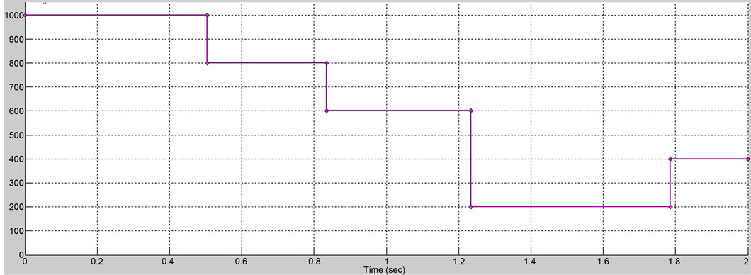
Figure 7. Signal builder showing change in irradiance.
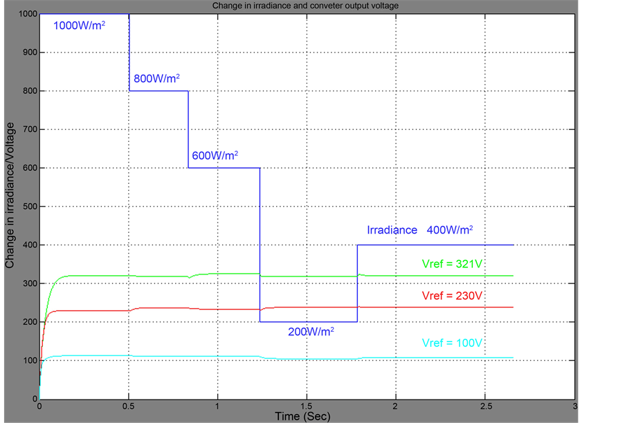
Figure 8. Simulation response of the converter under constant voltage method with open loop system.
of change in irradiance, the simulation response of the converter presents the oscillations with the voltage dip of −6 V and swell of +5 V. The reference voltage for which the converter voltage is to be maintained and the converter output voltage is given as the second input to the PI controller. The generated duty cycle (ΔD) is added to the initial duty cycle (Di). Figure 9 shows the block diagram of the closed loop system and the duty cycle generation by the PI controller
 (14)
(14)
Figure 10 shows the MATLAB Simulink model of the closed loop system. The values of KP and Ki are chosen as 0.25 and 0.001 by the method of trial and error.
The comparison made clearly depicts that there is an improvement in rise time and the voltage dip as well. And thus proves to be an efficient control method of the oscillations.
Figure 11 shows the simulation response of the converter under closed loop system and the comparison of the open loop and the closed loop systems are given in Table 2.
7. Hardware Results and Discussion
In order to confirm the feasibility of the proposed topology of prototype converter

Figure 9. Solar PV system with CVM control-closed loop.

Figure 10. Matlab-Simulink model of the constant voltage control method implemented in the converter-closed loop.

Figure 11. Simulation response of the converter under constant voltage method with closed loop system.
Table 2. Comparison of open loop and closed loop system.
model was built and implemented with PIC Microcontroller and driver circuits to obtain the same results as discussed in Section 6. The experimental setup is depicted in Figure 12. The converter implemented has a coupled inductor with turn’s ratio of 1:4, a capacitor value of 2.7 µF, 450 V and the value of another two capacitor is 100 µF, three diodes of type FR306 and a switch of IRF840 is used. The coupled inductor is designed in the ratio 1:4, with 40 turns in the primary and 160 turns in the secondary.
The switching frequency of the converter is considered as 10 kHz. The gate pulse and the output voltage waveforms for proposed boost converter mode are measured and observed as shown in Figure 13 and Figure 14.
For instance, the input voltage of the given prototype for boost mode is 5 V and obtains 45.2 V as output it is nearly ten times greater than the given input voltage is observed as shown in Table 3.
8. Conclusions
This paper shows that a PV system with the high step-up single switch isolated DC-DC converter with the constant voltage control block is capable of maintaining the output

Figure 12. Experimental set up of proposed converter.

Figure 13. Gate pulse generation from the driver circuit.

Figure 14. Output voltage waveform of proposed converter.
Table 3. Comparison of simulation and hardware results of proposed converter.
of the converter to be constant irrespective of the irradiation changes by changing the duty cycle of the converter. But due to the worst case change of irradiance, the simulation response of the converter presents the oscillations with the voltage dip of −6 V and swell of +5 V. The response of the closed loop system with the PI controller is also presented to give the PV system output with better response comparing the open loop system. Table 2 provided above proved the better performance of the closed loop system. Unlike the conventional control method with boost converters, the usage of constant voltage control and precisely defined high step-up isolated efficient single switch DC- DC converter proves to be the efficient control method of the oscillations. Hence, a high-precision constant voltage measurement can be easily achieved. The feasibility of the converter is investigated through the experimental results which are also presented and in the near future the experimental results of the entire system will be investigated.
Later, as a future scope, the decentralized PV systems can be considered where each PV system can have its own converter and the constant voltage control block that paves way for the sizing of panels as per the load requirement. In addition the switching scheme can also be designed to switch the PV system according to the load requirement.
Cite this paper
Alagammal, S., Rathina Prabha, Dr.N. and Aarthy, I. (2016) Centralized Solar PV Systems for Static Loads Using Constant Voltage Control Method. Cir- cuits and Systems, 7, 4213-4226. http://dx.doi.org/10.4236/cs.2016.713346
References
- 1. Parmar, M.N. and Jotangiya, V.G. (2014) Step-Up DC-DC Converter with High Voltage Gain Using Switched-Inductor Technique. International Journal of Engineering Development and Research, 2, 32-35.
- 2. Gopi, A. and Saravanakumar, R. (2014) High Step-Up Isolated Efficient Single Switch DC-DC Converter for Renewable Energy Source. Ain Shams Engineering Journal, 5, 1115-1127.
https:/doi.org/10.1016/j.asej.2014.05.001 - 3. Basanth, A.J. and Natarajan, S.P. (2013) Performance Analysis of Positive Output Super-Lift Re-Lift Luo Converter with PI and Neuro Controllers. IOSR Journal of Electrical and Electronics Engineering (IOSR-JEEE), 6, 21-27.
- 4. Parikh, J. and Parikh, K. (2013) Simulation of Incremental Conductance Mppt with Direct Control Method Using Cuk Converter. IJRET, 2, 557-566.
- 5. Chitra, A., Palackal, R.M.S., Viswanathan, K.G. and Nambiar, N. (2013) An Incremental Conductance Based Maximum Power Point Tracking Algorithm for a Solar Photovoltaic System. International Journal of Applied Engineering Research, 8, 2299-2302.
- 6. Tseng, K.C. and Liang, T.J. (2004) Novel High-Efficiency Step-Up Converter. IEE Proceedings of Electric Power Applications, 151, 182-190.
https:/doi.org/10.1049/ip-epa:20040022 - 7. Kobayashi, K., Matsuo, H. and Sekine, Y. (2004) A Novel Optimum Operating Point Tracker of the Solar Cell Power Supply System. IEEE Conference on Power Electronics, 3, 361-367.
- 8. Dall’Anese, E., Dhople, S.V., Johnson, B.B. and Giannakis, G.B. (2014) Decentralized Optimal Dispatch of Photovoltaic Inverters in Residential Distribution Systems. IEEE Transactions on Energy Conversion, 29, 957-967.
- 9. Liu, Y.-H., Huang, S.-C., Huang, J.-W. and Liang, W.-C. (2012) A Particle Swarm Optimization-Based Maximum Power Point Tracking Algorithm for PV Systems Operating under Partially Shaded Conditions. IEEE Transactions on Energy Conversion, 27, 1027-1035.
https:/doi.org/10.1109/TEC.2012.2219533 - 10. Aganah, K.A. and Leedy, A.W. (2011) A Constant Voltage Maximum Power Point Tracking Method for Solar Powered Systems. IEEE 43rd Southeastern Symposium on System Theory, 14-16 March 2011.
- 11. Gao, L.J., Dougal, R.A., Liu, S.Y. and Iotova, A.P. (2009) Parallel-Connected Solar PV System to Address Partial and Rapidly Fluctuating Shadow Conditions. IEEE Transactions on Industrial Electronics, 56, 101-110.