Journal of Electromagnetic Analysis and Applications
Vol.5 No.3(2013), Article ID:29201,5 pages DOI:10.4236/jemaa.2013.53015
The Precise Determination of Mass through the Oscillations of a Very High-Q Electromechanical System
![]()
Department of Physics (CFM/FSC), Federal University of Santa Catarina (UFSC), 88040-900, Florianópolis, Brazil.
Email: osvaldo.neto@ufsc.br
Received December 18th, 2012; revised January 20th, 2013; accepted February 3rd, 2013
Keywords: Mass; Magnetic Levitation; Electromechanical Oscillations
ABSTRACT
The present paper is based upon the fact that if an object is part of a highly stable oscillating system, it is possible to obtain an extremely precise measure for its mass in terms of the energy trapped in the system, rather than through a ratio between force and acceleration, provided such trapped energy can be properly measured. The subject is timely since there is great interest in Metrology on the establishment of a new electronic standard for the kilogram. Our contribution to such effort includes both the proposal of an alternative definition for mass, as well as the description of a realistic experimental system in which this new definition might actually be applied. The setup consists of an oscillating type-II superconducting loop subjected to the gravity and magnetic fields. The system is shown to be able to reach a dynamic equilibrium by trapping energy up to the point it levitates against the surrounding magnetic and gravitational fields, behaving as an extremely high-Q spring-load system. The proposed energy-mass equation applied to the electromechanical oscillating system eventually produces a new experimental relation between mass and the Planck constant.
1. Introduction
Mass is traditionally interpreted as the inertia content of a body [1]. The greater the parameter named mass (m), the more difficult it is for a given force F to produce a change in the objects state of motion. Newton’s Second Law describes this effect as F = ma, which serves as a formal definition for mass. However, the parameter mass is part of other dynamic quantities like momentum and energy. The measurement of such quantities in place of force and acceleration a can be advantageous in both experimental and theoretical grounds, in such a way that it may become convenient to adopt an alternative definition for mass based upon other dynamic quantities. In the present paper we describe how the establishment of a particular mathematical relation between mass and energy can lead to a neat new magneto-dynamic definition for the mass of an object, involving standardized constants of Nature.
We shall be interested in systems consisting of a macroscopic object in some way attached to an environment or device capable of producing over it some restitution force. That is, if the object is initially at rest and is suddenly subjected to an external force there will be a reaction against such force tending to restore the object to its initial location. We will specialize in the well known Basic Physics example of one such system, which is the spring-load set. We develop the theory in full detail to facilitate the comprehension of the comparisons to be made with the electromechanical system to be discussed in Sections 2 and 3. The spring-load system will be taken initially at rest with no stored energy, until on time t = 0 a fixed external force F is imposed upon it and kept constant thereafter. Newton’s Law describes the displacement x(t) of the spring and load as:
 (1)
(1)
Here k is the elastic constant of the spring. The initial conditions are . The solution of Equation (1) predicts a harmonic oscillation of the load around a position displaced of F/k from its initial position, with the amplitude of oscillation given by
 (2)
(2)
with  the frequency of the oscillations. Note that we are ideally assuming that no damping occurs, so that the total energy given by
 (3)
(3)
is conserved. Equation (3) states that the total energy contained in the system is given by the work done upon the system by the force F along the range of oscillation. By taking the time derivative of Equation (2) we obtain the velocity of the oscillating load, and realize that Equation (3) can be rewritten in the concise form
 . (4)
. (4)
Here vm is the maximum velocity of the load, given by . We note the following. Firstly, the form of Equation (4) independs on the particular expression for F, as well as it independs on the details of the restitution force, which is simply taken as linear in the displacement. Provided the system is initially fully at rest the imposition of any constant force at t = 0 will result in Equation (4). Secondly, its applicability of course depends upon the ability of the system in conserving energy and upon the possibility of measuring E. In this resonating state the parameter mass is the ratio between the energy of the state and the characteristic speed squared. Therefore, we have derived an alternative definition for mass that can be very convenient provided a suitable system is devised to explore it.
If damping is negligible the system oscillates in a state of dynamic equilibrium with all the force fields, internal or external, around it. We will be interested in the particular case of F = mg, the weight of the load oscillating in the vertical direction. In this case vm = g/ω, and the oscillations maximum amplitude is g/ω2.
Equation (4) can be useful provided energy losses are vanishingly small. However, it is well known that real spring-load systems are highly dissipative [2]. It is possible to define the quality factor Q for an oscillating system by the product of the frequency of oscillations times the total stored energy divided by the dissipated power. Therefore, the remainder of this paper will deal with the description of a system which by design would display a Q of 107 or more, so that the application of Equation (4) is justified. The present investigation is motivated by a particular (long-standing) Metrology problem, namely the determination of a new international standard for the kilogram in terms of an experimental expression involving well defined standardized parameters like the electronic charge and Planck’s constant. The current stage of such efforts has been described for instance in [3,4]. Our objective hereafter is to show that a relatively simple electromechanical system, in a single experiment, and adopting Equation (4) as the definition of mass might be able to produce an extremely precise measure for the mass of an object. The main result of this work is a new expression relating mass to other constants of Nature to be obtained by experiment (Section 2), followed in Section 3 by a full discussion of the principles behind the design of the experimental setup. Section 4 lists the Conclusions.
2. The Superconductor Electromechanical Oscillator (SEO)
In order to obtain a real application for Equation (4), we need to find a system in which losses are practically eliminated. Air friction can be virtually eliminated by working under high vacuum and at very low temperatures, to markedly decrease the atmosphere viscosity. Heat dissipation in the restitution process responsible for the oscillations is much more difficult to eliminate. However, as we show hereafter it has been possible to design a system in which all dissipative processes can be diminished to the point that the application of Equation (4) becomes realistic. This system has been devised and previously analyzed in detail by Schilling [5,6] (although its equations of motion had independently been published much earlier by Saslow [7]), and consists of a type-II superconducting rectangular loop of mass m, subjected to magnetic fields and gravity. In this section, we present the main results obtained from the analysis of the loop motion, including the proposal of a new relation between the loop mass and the total energy which follows from Equation (4).
The superconducting oscillator (SEO) is shown in Figure 1. The loop is hanging upright under the effect of gravity, with magnetic fields B1 and B2 normal to its surface. The need for two fields is explained in Section 3. These fields should be homogeneous upon the loop wire within a tolerance discussed in [5], assuming also that any sidewise drift motion is entirely negligible. The
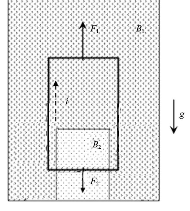
Figure 1. A type-II superconducting loop levitates under the action of two magnetic fields B1 and B2 greater than its lower critical field (B1 > B2 in the figure and the fields point into the page). F1 and F2 are the opposing vertical Lorentz forces that the fields impose upon the clockwise current (dashed line) induced in the loop when it is initially released and moves under the effect of gravity g.
tridimensional equivalent of this system, comprising three mutually perpendicular rectangular oscillating loops subjected to the field of a magnetized sphere has recently been discussed in the Letter [8], and utilized as a resonator as part of a quantum magneto-mechanical device. We will assume initial conditions identical to those for the spring-load system of Section 1, that is, the loop at rest with no currents flowing and thus no stored energy. The fact that the loop is superconducting in principle suggests that there will be no heat losses, but as we describe in Section 3 several conditions must be met in order that dissipative effects actually become negligible. For the moment let us assume that such steps have been taken, and no dissipation occurs if electrical currents flow around the loop. A consequence of such null electrical resistivity is that no electromotive force is developed around the loop, associated with current transport. When the loop is released and falls under the effect of gravity, the variation in the applied magnetic flux across its open area Φm will be compensated by flux Li generated by super currents i(t) around its perimeter, in such way that the application of Faraday’s Induction Law gives a null electromotive force ε:
 (5)
(5)
Here L is the self-inductance of the loop. This is an example of the property of flux conservation displayed by superconducting loops and rings. The loop will move with speed v described by Newton’s Law:
 (6)
(6)
In Equation (6) the last factor on the right is the result of the opposing magnetic forces F1 and F2 the fields B1 and B2 impose upon the currents in the two horizontal sides of the loop (see Figure 1). Here a is the length of the lower horizontal side of the loop subjected to B2. We define B0 ≡ B1 − B2. It must be stressed that none of the final results and conclusions depends on the precise determination of either a or of the magnetic fields, and neither on how sharp would be the boundary between these fields. From Figure 1, . Thus, from Equation (5) one obtains a relation between v and di/dt. Taking the time derivative of Equation (6) and eliminating di/dt from Equation (5) one obtains:
 (7)
(7)
which is the differential equation obeyed by the velocity of a harmonic oscillator. Assuming zero initial speed and an initial acceleration g, Equation (7) can be solved:
 . (8)
. (8)
From Equation (7), the natural frequency of the oscillations is . As the loop is released from rest, the assumed perfect flux and energy conservations will make this initial position the uppermost point of its oscillating path (measured from the middle point of its oscillations range), with
 . The position is described by the equation
 (9)
(9)
which is equivalent to (2) if F = mg. The maximum amplitude of the oscillating motion is g/Ω2. It is clear that such equations are equivalent to the ones in Section 1 for the spring-load system, with ω replaced by Ω. It is possible then to combine (5) and (6) to obtain an equation for the current i(t), which flows within a very thin layer close to the wires surface [5]:
 (10)
(10)
whose solution is
 (11)
(11)
for . We define
 .
.
In view of Equation (9), it is clear that Equation (3) also applies here, so that the same energy conservation  is obeyed, with vm= g/Ω from Equation (8), as in Section 1. We define Φ = Li0 as the flux threading the loop due to the average loop current value i0, resulting after a simple manipulation in E = 2Φ2/L. These two expressions for E lead to the following expression for the mass of the loop:
 (12)
(12)
This is the main result of this work. A superconducting quantum interference device (SQUID) with a proper gradiometer as probe, with the oscillating loop between its coils as “specimen” will measure the flux Φ due to the average current in the loop within a fraction of the flux quantum Φ0 = h/(2e), with h the Planck constant and e the electronic charge. Optical interferometric measurements will accurately give the speed vm, and L is a parameter for the loop, to be measured in advance in a separate experiment. Therefore, a simple experimental relation between mass and the Planck constant is obtained from this experiment (see [4] for a related discussion for the Watt Balance Method), provided Q is very large. The entire setup and theoretical analysis is considerably simpler than the Watt Balance Method adopted in recent attempts for the determination of the new standard for the kilogram [3,4].
In the next section, the actual design and implementation conditions necessary for this experiment are described in detail.
3. Implementation of the Loop-Oscillator Experiment
The design of the system has been discussed in [5,6], but we describe here the main details. However, this discussion does not include further details on the experimental techniques to be adopted in the measurement of the magnetic flux produced by the loop and of its position and speed, which lay beyond the scope of this paper and should be considered in due course. The design should start by the choice of a material to make the loop. Superconductors exist in the so-called types I and II [9]. The problem with type I materials is that magnetic levitation requires currents in the wire that would probably be too high for a type-I material to sustain, and the wire would become resistive. The application of B might also turn parts of the wire into the “intermediate state”, in which there are normal (resistive) regions mingled with superconducting regions, which is not desired here. By employing type-II materials, the mentioned difficulties with the magnitude of the currents and the intermediate state can be circumvented, since they are suitable for high currents and fields. However, type-II materials have problems of their own. Flux penetrates in type-II materials in the form of flux-lines (FLs) for fields greater than the lower critical field [9]. Figure 1 shows two magnetic fields B1 and B2 greater than the lower critical field, which are necessary in order to actually impose the full type-II superconducting conditions to the whole length of wire, avoiding the intermediate state of lower fields. The FLs carry a quantum of magnetic flux each and their cores contain electrons in the normal state. If these lines are not properly pinned, their motion under magnetic forces will generate heat. Fortunately, suitable working conditions can be devised to dramatically decrease such effects [5]. Commercial type-II superconductors are materials like Nb-Ti alloys. These materials contain nanometric-scale Ti inclusions that interact quite strongly with the FLs and pin then down. However, the motion of the loop will generate oscillating currents quite close to the wire surface [5], and these currents will produce a very small field that might disturb the FLs in an irreversible, hysteretic way, which must be avoided. If such fields are kept below a threshold value [5,10,11], there will be no major FLs displacements. The FLs will remain pinned, only slightly displaced from their equilibrium positions in the absence of that ripple field. The losses will be negligible for all practical effects, as calculated for a case study in [5]. This latter reference brings a detailed numerical example, in which a loop of mass of about 0.5 gram, subjected to a field difference B0 of 0.3 T, will oscillate at 178 Hz frequency with an amplitude of oscillations of about 8 μm.
Although we can conclude that losses within the wire can be made very small indeed, a remaining important source of energy loss is the drag of the loop against the cryostat atmosphere, even under high-vacuum. Temperature should be kept at the lowest possible level, preferably below 0.1 K. It has been shown in [5,8] that if the above conditions alone dominate the energy dissipation process a quality factor Q on the order of 1010 might be reached. However, other possible sources of energy dissipation should be avoided. Any electric or magnetic coupling of the loop with its surroundings will incur in extra losses. Eddy currents might be induced in metallic parts like the cryostat itself and the magnets that produce the field. Electrically insulating materials should therefore be used. In addition, the loop will produce an external oscillating field on the order of some gauss, and if permanent magnets are adopted the material used in the magnets should be hard enough not to display hysteresis under this kind of field. If a superconducting magnet is used to produce the field imposed to the loop the mutual inductance effect would be part of the measured value for L and there would be no major dissipative terms added. Just to conclude, special care must be taken also to avoid the excitation of sidewise oscillations of the loop.
It might be possible to relax the requirement of ultralow temperatures, and work at, say, 4.2 K and highvacuum. The viscosity of the atmosphere will increase the drag effect upon the loop by a fator of about 1000 [5,12]. The theoretical quality factor will drop from 1010 to the 107 range, which is comparable to that for electronic clocks used commercially, but even so the system will still be very close to ideal conditions. Experiments at 77 K might even be tried, since the drag effect will increase by a factor of about 50 between 4.2 and 77 K, which might still be acceptable. In this case the loop might be made of a high-temperature superconductor, and the whole setup would require simpler refrigeration techniques.
4. Conclusion
This paper has discussed in detail how an alternative definition of mass can be proposed for a very high-Q oscillating spring-load system. Provided the system starts entirely at rest, the application of a constant force at t = 0+ will lead to a 3-parameter relation between total energy, mass and the square of the oscillations speed. Such relation, Equation (4), is the expression of the equilibrium achieved by the load in the presence of the surrounding force fields. The concept is applied to the extremely high-Q superconducting loop-oscillator, which is a system that traps energy from the surrounding magnetic and gravitational fields and levitates in a nonhysteretic motion. The entirely new Equation (12) involves only three parameters and relates the mass of the loop with the Planck constant and the electronic charge. Such experimental system should be of great interest for Metrologists since it provides an essentially magneto-dynamic technique for obtaining an extremely precise measure of the mass of an object.
REFERENCES
- R. P. Feynman, R. B. Leighton and M. Sands, “The Feynman Lectures on Physics,” Addison-Wesley, Reading, 1963.
- A. P. French, “Vibrations and Waves,” W. W. Norton, New York, 1970.
- M. Stock, “The Watt Balance: Determination of the Planck Constant and the Redefinition of the Kilogram,” Royal Society Discussion Meeting: The New SI, 2011. http://www.bipm.org/utils/common/pdf/RoySoc/Michael_Stock.pdf
- R. Steiner, E. R. Williams, D. B. Newell and R. Liu, “Towards an Electronic Kilogram: An Improved Measurement of the Planck Constant and the Electron Mass,” Metrologia, Vol. 42, No. 5, 2005, pp. 431-441. doi:10.1088/0026-1394/42/5/014
- O. F. Schilling, “The Design of a Very High-Q superconductor Electromechanical Clock,” Brazilian Journal of Physics, Vol. 37, No. 2, 2007, pp. 425-428. doi:10.1590/S0103-97332007000300013
- O. F. Schilling, “A Superconductor Electromechanical Oscillator and Its Potential Application in Energy Storage,” Superconductor Science and Technology, Vol. 17, No. 3, 2004, pp. L17-L20. doi:10.1088/0953-2048/17/3/L01
- W. M. Saslow, “Electomechanical Implications of Faraday’s Law: A Problem Collection,” American Journal of Physics, Vol. 55, 1987, pp. 986-994. doi:10.1119/1.15281
- M. Cirio, G. K. Brennen and J. Twamley, “Quantum Magnetomechanics: Ultrahigh-Q Levitated Mechanical Oscillators,” Physical Review Letters, Vol. 109, 2012, 5 Pages, Article ID: 147206. doi:10.1103/PhysRevLett.109.147206
- M. Tinkham, “Introduction to Superconductivity,” Krieger, Malabar, 1980.
- A. M. Campbell, “The Response of Pinned Flux Vortices to Low-Frequency Fields,” Journal of Physics C: Solid State Physics, Vol. 2, No. 8, 1969, pp. 1492-1501. doi:10.1088/0022-3719/2/8/318
- A. M. Campbell, “The Interaction Distance between Flux Lines and Pinning Centres,” Journal of Physics C: Solid State Physics, Vol. 4, No. 18, 1971, pp. 3186-3198. doi:10.1088/0022-3719/4/18/023
- K. Edwards, LMNO Engineering, Research, and Software, Ltd., 2012. http://www.lmnoeng.com/Flow/GasViscosity.htm