Journal of Signal and Information Processing
Vol.10 No.04(2019), Article ID:96353,14 pages
10.4236/jsip.2019.104008
An Adaptive EMD Technique for Induction Motor Fault Detection
Manzar Mahmud1, Wilson Wang2*
1Electrical and Computer Engineering, Lakehead University, Thunder Bay, Canada
2Mechanical Engineering, Lakehead University, Thunder Bay, Canada

Copyright © 2019 by author(s) and Scientific Research Publishing Inc.
This work is licensed under the Creative Commons Attribution International License (CC BY 4.0).
http://creativecommons.org/licenses/by/4.0/


Received: October 13, 2019; Accepted: November 11, 2019; Published: November 14, 2019
ABSTRACT
Reliable induction motor (IM) fault detection techniques are very useful in industries to diagnose IM defects and improve operational performance. An adaptive empirical mode decomposition (EMD) technology is proposed in this paper for rotor bar fault detection in IMs. As the characteristic fault frequency will change with operating conditions related to load and speed, the proposed adaptive EMD technique correlates fault features over different frequency bands and intrinsic mode function (IMF) sidebands. The adaptive EMD technique uses the first IMF to detect the fault type and the second IMF as an indicator to predict the fault severity. It can overcome the problems of the sensitivity of sideband frequencies related to the speed and load oscillations. The effectiveness of the proposed adaptive EMD technique is verified by experimental tests under different motor conditions.
Keywords:
Induction Motors, Fault Detection, Broken Rotor Bars, Current Signal Processing, Empirical Mode Decomposition

1. Introduction
Induction motors (IMs) are commonly used in various industrial applications such as electric vehicles, machine tools and robots; in addition, IMs account for about 40% of the annual global electricity consumption [1]. Accordingly, reliable IM health condition monitoring is very useful in industries to identify IM failures to maintain motor power efficiency and avoid unexpected failures that may result in large productive and economic losses. IM defects are related to imperfections in stators, bearings, and rotors [2]. This work focuses on broken rotor bar (BRB) faults. The causes of rotor bar faults include excessive dynamic load stress, electromagnetic stress due to imbalance in the stator’s magnetic field, corrosion due to chemicals in the environment [3], etc. The consequences of BRB defect are increased vibration and noise, deterioration of the motor output efficiency, and early IM failure [4]. Since BRB faults will modulate the stator current signal, motor current signature analysis (MCSA) is more suitable in this fault detection than using vibration analysis. IM fault detection in this work will be based on MCSA.
Several MCSA-based techniques have been proposed in literature for BRB fault detection, based on spectral analysis of sidebands of the power frequency or its harmonics using methods such as multiresolution Taylor-Kalman approach [5], low-frequency load torque oscillations [6], auto-regression analysis [7], autoregressive-spectrum analysis [8] and high-resolution parameter estimation [9]. However, similar sidebands can also occur in spectral maps of healthy motors due to rotor asymmetries caused by manufacturing/assembly tolerances and connection coupling. BRB fault can also be detected based on signal processing techniques such as the wavelet transform [10], mathematical morphology [11] and orthogonal matching pursuit [12]. In using this wavelet transform-based analysis, the estimation of instantaneous frequency is not always efficient due to frequency smoothing imperfections.
Empirical mode decomposition (EMD) can solve several of these problems [13]. The EMD decomposes the signal into different frequency bands, known as intrinsic mode function (IMF), to process non-stationary signals for IM fault detection [14] [15]. However, when the signal length becomes longer, EMD generates extra number of IMFs due to the spline interpolation, which will not only increase processing time [16] [17], but also result in some false spectral components in the frequency bands [18]. In addition, our investigation shows that the IMF magnitude also depends on the hardware setup of data acquisition (DAQ) system.
Startup transient can be used as a means to detect BRB faults [13] [19]. The efficiency of these startup-based methods depends on the length of the transient (i.e., being long enough), which is difficult to apply in applications using soft-started inverter or variable-frequency-drive -fed motors [20]. Such startup-based methods are also not suitable to monitor IM conditions in actively running operation. On the one hand, another challenge in MCSA is how to estimate the severity of the BRB fault, as the current techniques depend on an accurate estimation of the magnitude of the sidebands [21] [22], which requires very accurate DAQ systems [23].
To tackle the aforementioned problems, an adaptive EMD technique is proposed in this work for BRB fault detection in IMs. It is new in the following aspects: 1) it can extract representative features for BRB fault detection, without the need of calculating side band frequencies. 2) This new technique enables the EMD to process signals with long length and diagnose the fault feature in the time domain, which is less sensitive to fault frequency variations.
The remainder of this paper is organized as follows. Section 2 discusses the proposed adaptive EMD technique. Its effectiveness of in IM fault detection is verified in Section 3. Some concluding remarks are summarized in Section 4.
2. Analysis of Proposed Adaptive EMD Technique
2.1. Overview
In general, spectral magnitude and fault sidebands are used to estimate the severity of BRB faults, but it is prone to generating false spectral components. As false frequency components do not inversely affect time series data, the proposed adaptive EMD technique will be undertaken in the time domain.
The relationship between two time series signals can be estimated by correlation coefficients of two stationary signals, but not for non-stationary signals whose statistical quantities are time varying. Fault related features from IMs could be non-stationery [23]. Different from general EMD processing, in the proposed adaptive EMD technique, the sliding window is determined adaptively by the estimation of the instantaneous period of the IMF; this provides the intrinsic relationship between the related signatures. In addition, the value of correlation is used to select the fault represented frequencies. Once the correlation value goes below to a certain threshold, the process will stop in calculating next IMF [20]. In this technique, only fault represented IMFs (which also have higher correlation coefficient) are calculated. Hence, it can process signals with any length. Figure 1 shows the block diagram of proposed adaptive EMD technique.
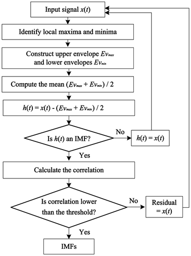
Figure 1. Block diagram of proposed adaptive EMD technique.
2.2. The Methodology
Due to the rotor asymmetry and imbalance in cage winding, there is a backward rotating field at slip frequency analogous to the forward rotating rotor [1]. As a result, current and induced electromagnetic signal are found at different slip frequencies. In addition, due to rotor oscillation, there exits an upper sideband current component in the stator winding [14]. Considering all these effects, sideband frequencies due to broken rotor bars will be
(1)
where is the power line frequency in Hz and s is the slip. As the EMD is based on the calculation of the envelope of maxima and minima of the input signal [18], fault related envelope can be independent of the . The line current is modeled as
(2)
where is the amplitude of the current, and is the phase angle of the sinusoidal line current.
Consider the sideband components with phase angle, then Equation (2) becomes
(3)
where and are the current and phase of the left sideband; and are related to right sideband quantities. is the mean value of the current amplitude. Equation (3) infers that the fault related envelope can be separable from the line frequency component, which can provide a better understanding of the fault features.
In the EMD process, the signal is decomposed into a set of IMFs. An IMF is a function that satisfies the following two requirements:
1) In the whole data set, the difference between the number of extrema and the number of zero-crossings points is either 0 or 1.
2) The mean value of the envelope due to the local maxima and local minima is zero.
Variable amplitude and frequency are represented as functions of time in the IMF. Spline interpolation can be used to determine the extreme points and form the negative and positive envelopes. The mean value of these two envelopes is subtracted from the original signal and the residual is investigated to see whether it satisfies these two criteria for IMF or not. After calculating each IMF, the correlation will be checked. If the correlation is above some threshold (usually determined by trials and errors) then the next IMF is computed.
On the other hand, from our systematic investigation, it is observed that the dot product between two IMFs is not zero. That means that EMD cannot strictly decompose IMF orthogonally. As a result, we cannot predict that fault frequency is particularly strict in one IMF, which can also be verified by correlation analysis as discussed in Section 3.
In processing, the Hilbert transform is applied to each of the IMFs such that
where and are the respective instantaneous amplitudes and instantaneous frequencies of the jth IMF, and n is the total number of IMF generated by EMD.
The residual is a monotonic function:
(5)
To calculate the IMF, the mean value of the envelope of input signal is computed as , where and are maximum and minimum values of the envelope. Then
(6)
If doesn’t satisfy the criteria for IMF, then is replaced by and the same process continues until it satisfies the criteria then,
(7)
Then the input signal for the next IMF is calculated as,
(8)
It is noted that applying MCSA in the IMF is highly dependent on the bandwidth of the DAQ system. The proof of the use of multiple IMFs to detect the BRB faults and operating points will be discussed in the following section.
3. Verification of the Proposed Adaptive EMD Technique
3.1. Experimental Setup
The experimental setup used in this test is shown in Figure 2. The tested motor (model 056T34F5301 from Marathon Electric) has 34 rotor bars and 24 stator slots. The speed of these IMs is controlled by a variable frequency drive (VFD) (from Delta Electronics Inc.). In this experiment, 50 Hz and 60 Hz supply frequencies are used, switching at 15 kHz. The IM output shaft is coupled to a gearbox (from Boston Gear) to adjust the speed ratio of the dynamometer. A magnetic particle clutch (PHC-50 from Placid Industries) is used as a dynamometer to provide variable load via an external DC power source. Current signals are collected by the use of a wireless smart current sensor DAQ system, developed in our research team [24], which can measure 2 - 3 phase current signals. The vibration signals corrected by using the 3D vibration sensor are used to estimate the motor shaft rotating speed, which is then used to compute the slip [24].
The current signals are collected when they have reached their rated load levels. The speeds and slip ( , slip) at full load in 50 Hz and 60 Hz are 2910 RPM (48.5 Hz, 3%) and 3498 RPM (58.3 Hz, 2.83%), respectively. Four load conditions are tested: coupled shaft with minimum load (33% of full load), medium load (67% of full load), and full load (100% of full load) controlled by adjusting the magnetic clutch current. Decoupled condition corresponds to zero load state (0% of full load) when the motor is disconnected with the gearbox.
3.2. Experimental Results
The effectiveness of the proposed adaptive EMD technique is evaluated under a series of tests corresponding to different load and speed operating conditions.
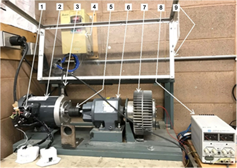
Figure 2. The experimental setup: (1) The wireless smart current sensors, (2) Motor under testing, (3) Vibration sensor, (4) Power source and VFD, (5) Coupling, (6) Speed-reduction gearbox, (7) magnetic clutch, (8) DC power source, (9) enclosure.
Five 1/3 HP IMs are tested in this work: two healthy IMs, and three faulted IMs with one, two, and three simulated BRBs, respectively. Figure 3 shows an example of an IM with two simulated BRBs.
At first, EMD is applied to the stator current. Figure 4(a) illustrates the first three IMFs of healthy motor and Figure 4(b) shows the IMFs of faulty motor using current signals at full load state. A comparison of Figure 4(a) and Figure 4(b) indicates that BRB can increase the oscillation of the IMF2 amplitude. In this case, only the first three IMFs are calculated, as after these the correlation coefficients are almost negligible.
Figure 5 shows the correlation between the signal and IMFs. It is seen that the first IMF, or IMF1, has the highest correlation value, as it has higher energy
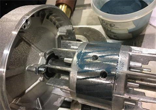
Figure 3. An example rotor with two simulated broken rotor bars. The power can help make drilling on the rotor bars.
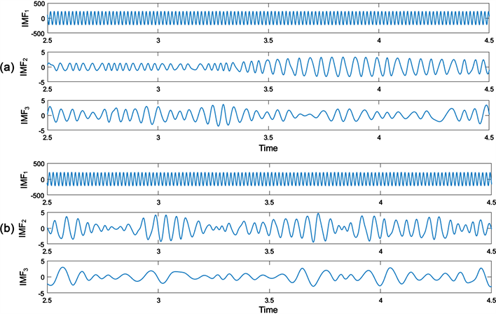
Figure 4. (a) The first three IMFs of healthy motor; (b) The first three IMFs of faulty motor, with current at full load condition.
frequency components. IMF2 mainly includes RBR related freqeuency harmonics, while the remaining correlation values after IMF2 are very small. It is important to note that although BRB sideband components exits in all the IMFs, the correlation coefficients decrease with the increase of the IMF order, up to negligible. In our proposed adaptive EMD technique, the IMF1 will be used to detect the rotor bar faults and IMF2 is applied to diagnose the fault conditions.
Different from the previous theoretical analysis in the literature where BRB feature is extracted from spectral magnitude of IMFs without considering fundamental line frequencies, the proposed adaptive EMD technique considers both the component of fundamental line frequency and the fault related sidebands to predict rotor bar fault.
Figure 6 shows the processing results of healthy and faulty motors at no load and full load condition, respectively. It is seen that spectra of stator current signals cannot detect rotor bar faults at no load or low load conditions. In our proposed adaptive EMD technique, the Hilbert transform is performed for the first
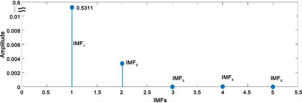
Figure 5. Correlation values between the signal and IMFs.

Figure 6. Spectra of the IMF1: ((a), (b)) for healthy IMs; ((c), (d)) for faulty motors; corresponding to: ((a), (c)) no load condition; ((b), (d)) full load conditions.
IMF before doing spectral analysis. It is also noted that a new frequency pattern of is added to the fundamental frequency domain in the electromagnetic force profile. Torque and speed fluctuations will result in some extra sideband components. It means that if the motor speed is fixed, the sidebands may disappear, which is the reason sometimes sideband components may not be recognized in one or two sides.
In general, MCSA-based BRB fault detection uses the spectral magnitude of these sideband frequencies to determine the severity of the faults. However, a major problem for such an approach is that speed/load oscillation can generate some extra frequency components in the vicinity of fault characteristic frequency and its harmonics, which will result in false alarms in online IM health condition monitoring. The proposed adaptive EMD technique applies a new approach to distinguish these false alarms and real IM faults. Compared to low speed load oscillation, the variation of BRB frequencies are much higher in MCSA spectrum. From this investigation, it can be found that from no load to full load conditions, the BRB frequency component varies from 60.5 Hz to 63.39 Hz with a difference of 2.89 Hz; however, the literature indicates that frequency variation is about 0.035 Hz only, which is almost negligible. Therefore, the proposed adaptive EMD technique can distinguish false alarms to improve IM monitoring accuracy.
To further investigate the severity of the fault under different operating conditions, Figure 7(a) shows the fluctuation of IMF2 at 3600 RPM for 1 and 3 BRBs at the full load condition. It is seen that the magnitude of IMF2 with 3 BRBs is greater than the magnitude of 1 BRB. Figure 7(b) illustrates the results of IMF2 for a motor with 3 BRBs at two respective speeds of 3600 RPM and 3000 RPM, at full load condition.
Figure 8 presents the results of IMF2 at medium load state (i.e., 67% of full load) for different fault and speed conditions. It is seen that the magnitude of IMF2 at 3600 RPM is much higher than that at 3000 RPM. Therefore, the distinction for different motor speed is clear, even though the distinction for different number of BRBs becomes less clear in this case.
Figure 9 and Figure 10 illustrate the impact of small load and no load conditions (33% versus 0%) on different fault states and different operating conditions. The amplitude of IMF2 changes with the variation of load and fault severity. In this work it is found that the amplitude of the IMF2 increases with the increase of load and with the increase in number of BRB.
3.3. Discussion of the Results
From the above result analysis, it is seen that in a 34-bar rotor, if one bar is broken it influences 1/34 times of the total operation. But if 3 bars are broken it will affect 3/34 times of the total operation. Increasing the number of BRBs will result in asymmetry and saturation in the breakage area. The adjacent bars of broken bars will draw more current in this case. As a result, local flux density and
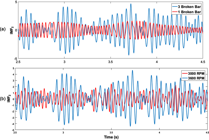
Figure 7. IMF2 results at full load condition: (a) At 3600 RPM for motors with 1 and 3 broken rotor bars; (b) For a motor with 3 broken bars at different speeds.
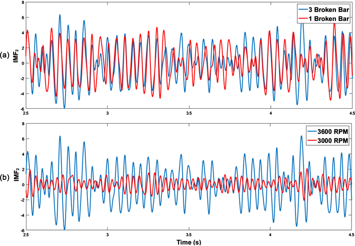
Figure 8. IMF2 results at medium load (67%) condition: (a) at 3600 RPM for motors with 1 and 3 broken rotor bars; (b) for a motor with 3 broken bars at different speeds.

Figure 9. IMF2 results at small load (33%) condition: (a) at 3600 RPM for motors with 1 and 3 broken rotor bars; (b) for a motor with 3 broken bars at different speeds.
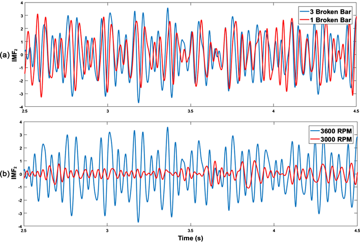
Figure 10. IMF2 results at no load (0%) condition: (a) At 3600 RPM for motors with 1 and 3 broken rotor bars; (b) For a motor with 3 broken bars at different speeds.
fluctuation increase. Similar phenomena can be observed in load increment. Increasing load level causes additional current in breakage area, which also causes saturation and fluctuation. In addition, motor load increment will increase the slip, the difference between synchronous speed and rotor speed; it also increases the IMF amplitude. But with the increase of speed, slip decreases. This slip reduction will lead to amplitude reduction of IMF. In this work the analysis is undertaken in the time domain whereas conventional EMD-based BRB analysis is performed in the frequency domain. In general, spectral analysis cannot provide accurate results in no load or light load condition (Figure 9 and Figure 10).
4. Conclusion
An adaptive EMD technique is proposed in this work for motor BRB fault detection, using current signals. In the proposed adaptive EMD technique, the correlation of fault features over different frequency bands and IMFs are processed for BRB analysis, to overcome the problems of the sensitivity of sideband frequencies to the speed and load oscillation. The adaptive EMD technique uses the first IMF for fault detection, and applies the second IMF to predict the fault severity. The effectiveness of the proposed adaptive EMD technique has been verified by experimental tests under different motor conditions. Test results have shown that the proposed adaptive EMD technique can be used effectively for BRB fault diagnosis. It is also robust to load conditions. It can also recognize BRB defect under no load conditions, which is very valuable to motor maintenance operations. This new technology has great potential to be implemented for IM condition monitoring in real indutrial applications.
Acknowledgements
This work was supported in part by Natural Sciences and Engineering Research Council of Canada (NSERC), Bare Point Water Treatment Plant, and eMech Systems Inc.,
Conflicts of Interest
The authors declare no conflicts of interest regarding the publication of this paper.
Cite this paper
Mahmud, M. and Wang, W. (2019) An Adaptive EMD Technique for Induction Motor Fault Detection. Journal of Signal and Information Proces- sing, 10, 125-138. https://doi.org/10.4236/jsip.2019.104008
References
- 1. Saidur, R. (2010) A Review on Electrical Motors Energy Use and Energy Savings. Renewable and Sustainable Energy Reviews, 14, 877-898. https://doi.org/10.1016/j.rser.2009.10.018
- 2. Nandi, S., Toliya, H. and Li, X. (2005) Condition Monitoring and Fault Diagnosis of Electric Motors—A Review. IEEE Transactions on Energy Conversion, 20, 719-729. https://doi.org/10.1109/TEC.2005.847955
- 3. Li, D.Z., Wang, W. and Ismail, F. (2015) A Spectrum Synch Technique for Induction Motor Health Condition Monitoring. IEEE Transactions on Energy Conversion, 30, 1348-1355. https://doi.org/10.1109/TEC.2015.2454440
- 4. Naha, A., et al. (2016) A Method for Detect Half-Broken Rotor Bar in Lightly Loaded Induction Motors Using Current. IEEE Transactions on Instrumentation and Measurement, 65, 1614-1625. https://doi.org/10.1109/TIM.2016.2540941
- 5. Trujillo-Guarjardo, L., et al. (2018) A Multiresolution Taylor-Kalman Approach for Broken Rotor Bar Detection in Cage Induction Motors. IEEE Transactions on Instrumentation and Measurement, 67, 1317-1328. https://doi.org/10.1109/TIM.2018.2795895
- 6. Kim, H., et al. (2016) Reliable Detection of Rotor Faults under the Influence of Low-Frequency Load Torque Oscillations for Applications with Speed Reduction Coupling. IEEE Transactions on Industry Applications, 52, 1460-1468. https://doi.org/10.1109/TIA.2015.2508423
- 7. Dias, C.G. and Pereira, F.H. (2018) Broken Rotor Bars Detection in Induction Motors Running at Very Low Slip Using a Hall Effect Sensor. IEEE Sensors Journal, 18, 4602-4613. https://doi.org/10.1109/JSEN.2018.2827204
- 8. Zhang, Z., Ren, Z. and Huang, W. (2003) A Novel Detection Method of Motor Broken Rotor Bars Based on Wavelet Ridge. IEEE Transactions on Energy Conversion, 18, 417-423. https://doi.org/10.1109/TEC.2003.815851
- 9. Kim, Y., Youn, Y., Hwang, D., Sun, J. and Kang, D. (2013) High-Resolution Parameter Estimation Method to Identify Broken Rotor Bar Faults in Induction Motors. IEEE Transactions on Industrial Electronics, 60, 4103-4117. https://doi.org/10.1109/TIE.2012.2227912
- 10. Ordaz-Moreno, A., et al. (2008) Automatic Online Diagnosis Algorithm for Broken-Bar Detection on Induction Motors Based on Discrete Wavelet Transform for FPGA Implementation. IEEE Transactions on Industrial Electronics, 55, 2193-2202. https://doi.org/10.1109/TIE.2008.918613
- 11. Rangel-Magdaleno, J.D.J., Peregrina-Barreto, H., Ramirez-Cortes, J.M., Gomez-Gil, P. and Morales-Caporal, R. (2014) FPGA-Based Broken Bars Detection on Induction Motors under Different Load Using Motor Current Signature Analysis and Mathematical Morphology. IEEE Transactions on Instrumentation and Measurement, 63, 1032-1040. https://doi.org/10.1109/TIM.2013.2286931
- 12. Morales-Perez, C., Rangel-Magdaleno, J., Peregrina-Barreto, H., Amezquita-Sanchez, J.P. and Valtierra-Rodriguez, M. (2018) Incipient Broken Rotor Bar Detection in Induction Motors Using Vibration Signals and the Orthogonal Matching Pursuit Algorithm. IEEE Transactions on Instrumentation and Measurement, 67, 2058-2068. https://doi.org/10.1109/TIM.2018.2813820
- 13. Lei, Y., Lin, J., He, Z. and Zuo, M.J. (2013) A Review on Empirical Mode Decomposition in Fault Diagnosis of Rotating Machinery. Mechanical Systems and Signal Processing, 35, 108-126. https://doi.org/10.1016/j.ymssp.2012.09.015
- 14. Rangel-Magdaleno, J., Peregrina-Barreto, H., Ramirez-Cortes, J. and Cruz-Vega, I. (2017) Hilbert Spectrum Analysis of Induction Motors for the Detection of Incipient Broken Rotor Bars. Measurement, 109, 247-255. https://doi.org/10.1016/j.measurement.2017.05.070
- 15. Abd-el-Malek, M., Abdelsalam, A.K. and Hassan, O.E. (2017) Induction Motor Broken Rotor Bar Fault Location Detection through Envelope Analysis of Start-Up Current Using Hilbert Transform. Mechanical Systems and Signal Processing, 93, 332-350. https://doi.org/10.1016/j.ymssp.2017.02.014
- 16. Ebrahimia, F., Setarehdana, S.K. and Nazeranb, H. (2015) Automatic Sleep Staging by Simultaneous Analysis of ECG and Respiratory Signals in Long Epochs. Biomedical Signal Processing and Control, 18, 69-79. https://doi.org/10.1016/j.bspc.2014.12.003
- 17. Kabir, M.A. and Shahnaz, C. (2012) Denoising of ECG Signals Based on Noise Reduction Algorithms in EMD and Wavelet Domains. Biomedical Signal Processing and Control, 7, 481-489. https://doi.org/10.1016/j.bspc.2011.11.003
- 18. Sanchez, J., Ortigueira, M., Rato, R. and Trujillo, J. (2016) An Improved Empirical Mode Decomposition for Long Signals. SIGNAL 2016: The First International Conference on Advances in Signal, Image and Video Processing, Lisbon, 58-62.
- 19. Morinigo-Sotelo, D., Romero-Troncoso, R.J., Panagiotou, P.A., Antonio-Daviu, J.A. and Gyftakis, K.N. (2018) Reliable Detection of Rotor Bars Breakage in Induction Motors via MUSIC and ZSC. IEEE Transactions on Industry Applications, 54, 1224-1234. https://doi.org/10.1109/TIA.2017.2764846
- 20. Faiz, J., Ghorbanian, V. and Ebrahimi, B. (2014) EMD-Based Analysis of Industrial Induction Motors with Broken Rotor Bar for Identification of Operating Point at Different Supply Modes. IEEE Transactions on Industrial Informatics, 10, 957-966. https://doi.org/10.1109/TII.2013.2289941
- 21. Ayhan, B., Trussell, H., Chow, M. and Song, M. (2008) On the Use of a Lower Sampling Rate for Broken Rotor Bar Detection with DTFT and AR-Based Spectrum Methods. IEEE Transactions on Industrial Electronics, 55, 1421-1434. https://doi.org/10.1109/TIE.2007.896522
- 22. Chen, X., Wu, Z. and Huang, N.E. (2010) The Time-Dependent Intrinsic Correlation Based on the Empirical Mode Decomposition. Advances in Adaptive Data Analysis, 2, 233-265. https://doi.org/10.1142/S1793536910000471
- 23. Huijsing, J. (2018) Smart Sensor Systems: Why? Where? How? In: Meijer, G.C.M., Ed., Smart Sensor Systems, John Wiley & Sons, Ltd., UK, 1-21. https://doi.org/10.1002/9780470866931.ch1
- 24. Luong, P. and Wang, W. (2019) Smart Sensor-Based Synergistic Analysis for Rotor Bar Fault Detection of Induction Motors. IEEE/ASME Trans. on Mechatronics, in Press.