Surgical Science
Vol.05 No.12(2014), Article ID:52031,12 pages
10.4236/ss.2014.512079
The Effect of Projection Microstereolithographic Fabricated Implant Geometry on Myocutaneous Revascularization
Ross M. Clark1, Kirsten N. Cicotte2, Paul G. McGuire3, Elizabeth L. Hedberg-Dirk2, Thomas R. Howdieshell1*
1Department of Surgery, University of New Mexico Health Sciences Center, Albuquerque, New Mexico
2Center for Biomedical Engineering, University of New Mexico Health Sciences Center, Albuquerque, New Mexico
3Department of Cell Biology and Vascular Physiology, University of New Mexico Health Sciences Center, Albuquerque, New Mexico
Email: *thowdieshell@salud.unm.edu
Academic Editor: Einar Arnbjornsson, Skane University, Sweden
Copyright © 2014 by authors and Scientific Research Publishing Inc.
This work is licensed under the Creative Commons Attribution International License (CC BY).
http://creativecommons.org/licenses/by/4.0/


Received 24 September 2014; revised 20 October 2014; accepted 15 November 2014
ABSTRACT
Understanding cell behavior inside three-dimensional (3D) microenvironments with controlled spatial patterning of physical and biochemical factors could provide insight into the basic biology of tissue engraftment, vascular anastomosis, and revascularization. A simple layer by layer projection microstereolithography (PµSL) method was utilized to investigate the effects of a nonporous and porous bioinert barrier on myocutaneous flap engraftment and revascularization. A cranial- based, peninsular-shaped myocutaneous flap was surgically created on the dorsum of C57Bl6 mice. Porous (SP) and nonporous (S) silicone implants were tailored to precise flap dimensions and inserted between the flap and recipient bed prior to sutured wound closure. Porous implant myocutaneous flaps became engrafted to the recipient site with complete viability. In contrast, distal cutaneous necrosis and resultant flap dehiscence was evident by day 10 in nonporous implant flap mice. Laser speckle contrast imaging demonstrated flap revascularization in (SP) mice, and markedly reduced distal flap reperfusion in (S) mice. Histologic analysis of day 10 (SP) flaps revealed granulation tissue rich in blood vessels and macrophages growing through the implant pores and robust neovascularization of the distal flap. In contrast, the nonporous implant prevented tissue communication between recipient bed and flap with lack of bridging inflammatory cells and neovasculature and resultant distal tissue necrosis. We have fabricated porous and nonporous silicone implants via a simple and inexpensive technique of PµSL. Using a graded-ischemia wound healing model, we have shown that porous implants allowed contact between flap and recipient bed resulting in proximal flap arteriogenesis and neovascularization of the distal flap. Future research will utilize variations in implant pore size, spacing, and location to gain a better understanding of the cellular and molecular mechanisms responsible for myocutaneous flap engraftment, vascular anastomosis, and revascularization.
Keywords:
Wound Healing, Angiogenesis, Stereolithography, Implant Geometry

1. Introduction
One of the most potent stimuli for new blood vessel growth or neovascularization is ischemia, which induces capillary growth to restore adequate oxygen delivery to hypoxic tissues [1] . Functional revascularization is essential for the successful healing of cutaneous wounds and involves: the coordinated expression and activity of angiogenic growth factors, chemokines, extracellular proteinases, and cell surface molecules; the recruitment of circulating inflammatory cells; and the sprouting of new vessels from pre-existing vasculature [2] - [4] . Sprouting requires the activation of quiescent endothelial cells by an angiogenic stimulus. Secretion of proteases by the activated endothelium allows alteration of the surrounding basal lamina and the tissue ahead and growth towards attractive cues. Angiogenic sprouts emerge from parental vessels and eventually fuse with another sprout or a pre-existing vessel, a process called anastomosis [5] .
Whereas an autologous split-thickness skin graft with an inherent vasculature purportedly becomes perfused in a matter of days by direct anastomosis or inosculation of pre-existing graft vessels with those of the recipient site, avascular skin and tissue equivalents must become perfused entirely by neovascularization from the recipient wound bed, each process dependent upon tissue contact or engraftment [6] . Despite extensive work documenting the importance of blood flow in angiogenesis and vessel remodeling, little is known about vascular anastomosis at the cellular and molecular level. Recent research suggests that the process of anastomosis is not solely driven by chemotactic or haptotactic mechanisms, but rather represents a contact-based process that requires the exploratory properties of specialized endothelial cells and bridging macrophages [7] .
Projection microstereolithography (PµSL) uses computer-controlled digital light projection to spatially control solidification of a liquid photocurable polymer resin. Structural parameters of the fabricated construct such as pore size, configuration, and density can be precisely controlled [8] . Many applications exist for this technique of microscale manufacturing including microbioreactors to support tissue growth, micromatrices for drug delivery and detection, and biochemical integrated circuits that can simulate biological systems [9] . Here we utilized stereolithographic fabricated implants to study the effect of physical contact between myocutaneous flap and recipient bed on flap revascularization.
2. Materials and Methods
2.1. Projection Microstereolithography Apparatus and Printing Protocol
The projection apparatus consisted of a data projector (Epson Model 534A, Seiko Epson Corp., Nagano, Japan), a converging lens, and a staging device [8] . Using a lens with a 15 cm focal distance (Edmund Optics, model number NT 32-975), objects of consistently high quality were produced from images that occupied roughly 1/4 of the computer screen space. A simple staging device was constructed using two drawer slides as the basis for its vertical alignment. Twisting a threaded rod attached to a T-nut provided the mechanism for fine vertical control.
The printing solution was prepared with an aliquot of 90 mg of phenylbis(2,4,6-trimethylbenzoyl)-phosphine oxide (BAPO) dissolved in 900 µL of chloroform. Three grams of methacrylate-terminated polydimethylsiloxane (PDMS-MA) was added to the photoinitiator solution (BAPO) and mixed. The implants were fabricated using PµSL controlled by computer-generated masks and projected onto the polymer solution using Microsoft PowerPoint (Microsoft, Inc., Redmond, WA). Post-fabrication implant thickness and geometry was analyzed using ImageJ software (National Institutes of Health). The implants were sterilized with hydrogen peroxide gas (Sterrad, Advanced Sterilization Products, Ethicon, Inc., Irvine, CA).
2.2. Mouse Myocutaneous Flap Model and Wound Morphology Analysis
All animals were treated humanely in accordance with the National Research Council’s “Guide for the Care and Use of Laboratory Animals” as part of a protocol approved by the University of New Mexico’s animal review committee. C57Bl6 mice, ages 8 - 12 weeks (Jackson Laboratory, Bar Harbor, ME), underwent anesthesia with isoflurane (1% - 3%) via nose cone inhalation. Postoperative analgesia was provided using a single subcutaneous dose (0.01 mg/kg) of buprenorphine hydrochloride. A total of 15 mice were used for the study, 5 mice in each group (5 unoperated or control mice, 5 flaps with porous [SP] and 5 flaps with nonporous [S] implants).
After maintenance of inhalation anesthesia, hair was removed from the mouse back skin using electric clippers, and the site was prepped with povidine-iodine and 70% ethanol. The mice underwent surgical creation of a peninsular flap (3 cm in length and 1.5 cm in width) consisting of skin, adipose tissue, and panniculus carnosus muscle by making three soft tissue incisions. The flap was elevated cranially and reapproximated to the back skin with 6-0 monofilament sutures [10] . Porous and nonporous PDMS implants were tailored to precise flap dimensions and inserted between the flap and recipient bed prior to sutured wound closure. After surgery, each animal was singly housed and received water and food ad libitum.
At Day 10 post-surgery, photographs of the dorsal flap were taken for analysis using a Nikon D70 digital camera (Nikon Inc., Melville, NY) equipped with a macro lens. The percentage of viable flap surface area was computed using an electronic grid and standard planimetry method [11] .
2.3. Laser Speckle Perfusion Imaging
At days 0, 2, 5, and 10 after surgery, each animal underwent inhalation anesthesia in prone position, and laser speckle perfusion imaging was performed with the Full-Field Laser Perfusion Imager (FLPI, Moor Instruments, Essex, UK) in low-resolution/high speed setting at a display rate of 25 Hz, time constant of 0.3 s, and camera exposure time of 20 ms. The instrument head containing the charged coupled device camera was positioned 15 cm above the mouse back tissue surface using an articulating arm. The contrast images were processed to produce a scaled colored-coded Live Flux image (red, high perfusion; blue, low perfusion), which correlated with the blood flow velocity in the tissue.
Data were collected using temporal resolution laser speckle perfusion imaging and analyzed using Moor FLPI Review Software. The surgically created flap was divided into cranial, central, and caudal regions of interest (ROI) of equal-imaged surface area. Data from each ROI was exported to R Statistical Analysis software (R Foundation, Vienna, Austria). A five period simple moving average was applied which demonstrated excellent fidelity to the raw data plot. An automated framework to provide precise sampling of the moving average plot at the time of end-expiration was created to record the mean perfusion in the absence of motion artifact from mouse respiratory effort. This procedure was repeated for each mouse ROI and timepoint.
Representative frames of temporal resolution data were identified at end-expiration for both porous and nonporous implant experimental arms at postoperative Day 10. The perfusion data from the surgically created flap was selected and exported to Matlab R2013b software (Mathworks Inc., Natick, MA). A 3D surface plot was created from the matrix data with surrounding floor set to average preoperative perfusion to illustrate the flap changes relative to the unoperated state.
The FLPI instrument reports perfusion in arbitrary units. To assign values to a measurement, the imager was calibrated using a reference flux signal generated by the laser light scattered from a suspension of polystyrene microspheres in water undergoing thermal or Brownian motion. From kinetic theory, the average velocity of the microspheres is proportional to the square root of the temperature in Kelvin. All measurements were performed at a room temperature of 20˚C (293˚ Kelvin) [12] .
2.4. Tissue Harvest, Histology, and Immunochemical Staining
Mice were humanely sacrificed by CO2 inhalation at 0 hours (control) and Day 10 for control skin or flap tissue harvest and histologic examination. The unoperated back skin (controls) or entire flap was excised using sterile technique and bisected in transverse fashion to directly correspond to the cranial and caudal laser image ROIs. The tissue was fixed in IHC Zinc Fixative (BD Biosciences-Pharmingen, San Diego, CA) for 24 hours, pro- cessed, and paraffin-embedded. Serial sections (4 µm) were dewaxed in xylene, taken through graded ethanol, and then hydrated in phosphate-buffered saline solution and stained with hematoxylin and eosin (Vector Laboratories, Burlingame, CA) for brightfield microscopy.
Blood vessel and macrophage identity were determined by CD-31 and F4/80 immunostaining respectively. After dewaxing and hydration, sections were incubated for 10 minutes in 3% hydrogen peroxide in methanol to block endogenous peroxidase activity, washed in phosphate-buffered saline, and incubated with primary antibody (rat anti-mouse CD-31, 1:50, BD Biosciences-Pharmingen; rat anti-mouse F4/80, ab6640, 1:300, Abcam Inc., Cambridge, MA) for 1 hour at room temperature in a humidified chamber. Next, the sections were incubated with a biotinylated secondary antibody (anti-rat immunoglobin horseradish peroxidase kit, 1:50, BD Biosciences- Pharmingen) or fluorescent secondary antibody (Alexa Fluor 555, 1:500, Invitrogen, Eugene, OR) for 30 minutes followed by 3,3’-diaminobenzidine chromogen for 5 minutes for light microscopy. The sections for bright- field microscopy were counterstained with Vector Hematoxylin QS (Vector Laboratories) with quick immersion. The 3,3’-diaminobenzidine substrate-chromogen resulted in a brown-colored precipitate at the antigen site. Sections for fluorescent examination were mounted using ProLong Gold Antifade Reagent with DAPI (Invitrogen). DAPI (4’,6-diamino-2-phenylindole) nuclear staining provided definition for tissue orientation.
2.5. Microvascular Density Determination and Macrophage Quantification
Skin, subcutaneous tissue, panniculus muscle, and granulation tissue region vessel counts and vascular luminal cross-sectional surface areas were determined with image analysis of CD-31 immunostained sections. Multiple, consistent, full-thickness flap biopsies were analyzed for each proximal and distal section with a total mean value reported. A Zeiss microscope (Carl Zeiss Microimaging, Thornwood, NY) with attached digital camera was used for image acquisition. The magnified image (200×) of the slide section was analyzed with SlideBook image analysis software (SlideBook 5.5, Intelligent Imaging Innovations, Santa Monica, CA). Vessels in each section were defined by the circular or ovoid image of the brown endothelial walls. Capillaries, arterioles, and venules were counted. For determination of area, the minimum major axis of each vessel was measured. The calibration scale was set with a micrometer scale. Vessel count and vascular surface area estimates were reported per square millimeter of flap tissue [10] .
Maximal fluorescent intensity of F4/80 fluorescent immunostaining was utilized to quantify macrophage presence in flap tissue. Multiple, consistent sections were examined and photographed using two-channel fluorescent microscopy at 200× magnification (Axioskop; Carl Zeiss Microimaging). Captured images were analyzed for red fluorescent intensity (CY3) using SlideBook image analysis software with mean values reported. Maximal fluorescent intensity (MFI) was reported (×103) per square millimeter of flap tissue area.
2.6. Statistical Analysis
All data are expressed as the mean values ± standard error of the mean. Data was analyzed using Microsoft Excel 2013/XLSTAT-Pro Version 2013.5.08 software (Addinsoft Inc., Brooklyn, NY). Analysis of two samples was performed with Student’s t test, and statistically significant interactions are demarcated by asterisks. A P value of 0.05 or less was considered statistically significant. Vessel counts and vascular surface area are reported with box plots created using the mean (cross), median (center horizontal line), 75th percentile (upper box hinge), 25th percentile (lower box hinge), and inclusive data points within 1.5 times the interquartile range. Moderate outliers beyond this range are represented by solid dots.
3. Results
3.1. Implant Morphology
Image analysis calibrated to micrometer scale was used to measure implant thickness and pore size and spacing dimensions. Implants were fabricated with a thickness of 134 ± 10 µm (S) and 122 ± 30 µm (SP). The difference in thickness between implants was not statistically significant. Porous implants contained circular- shaped pores of 271 ± 1 µm average diameter, horizontal spacing of 490 ± 1 µm, and vertical spacing of 602 ± 1 µm (Figure 1).
3.2. Flap Viability and Histopathology
All mice in each group survived until scheduled sacrifice. Digital photographic images of serial flaps were utilized for planimetric determination of flap surface viability. All porous implant myocutaneous flaps (n = 5) rapidly engrafted to the recipient bed (paraspinal musculature) resulting in complete epidermal viability other than a superficial distal corner eschar in select mice. There was a significant reduction in flap viability in nonporous implant mice evidenced by early epidermolysis (Days 2-5) of the distal portion of the flap in all mice (n = 5) with progression to focal full-thickness cutaneous necrosis and dehiscence of the distal flap from the recipient bed and adjacent skin by Day 10 in three of the five mice (Figure 2).
Brightfield microscopic examination of Day 10 flap histologic sections confirmed the importance of engraftment in flap revascularization. Hematoxylin and eosin staining of distal porous flap sections revealed epidermal regeneration, viable panniculus carnosus muscle, and well-vascularized granulation tissue bridging the flap with recipient bed via pores in the implant. In contrast, histologic features of the identical region of Day 10 nonporous implant flaps included isolated epidermal and dermal necrosis, scattered panniculus muscle bundle necrosis, and lack of bridging granulation between the recipient site and flap due to the physical barrier of the nonporous implant (Figure 3).
3.3. Laser Speckle Perfusion Imaging of Implant Flaps
Laser speckle contrast examination of preoperative back skin and postoperative implant flaps was utilized to analyze the pattern of myocutaneous flap ischemia and functional revascularization. Prior to surgical intervention (Pre-op), mouse back skin perfusion was consistent across cranial, central, and caudal ROIs in both groups of mice. In both implant groups, creation of the cranial-based, peninsular-shaped myocutaneous flap produced a comparable gradient of ischemia (Post-op) as a result of surgical incision of the flap’s segmental thoracolumbar vessels and perforating paraspinal muscular blood supply (Figure 4).
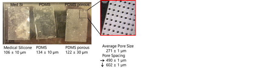
Figure 1. Photographs of fabricated porous (PDMS porous) and nonporous (PDMS) implants. A commercially available piece of silicone (Med Si) is shown for comparison. The thickness of each is depicted below its image. The insert reveals pore geometry with text documenting pore size as well as horizontal and vertical spacing dimensions.

Figure 2. Flap viability. (A) Percent viability of porous and nonporous implant flaps (*P < 0.05 versus porous implant flap); (B) Photograph of day 10 nonporous implant flap revealing wound dehiscence and ulcer (arrow).
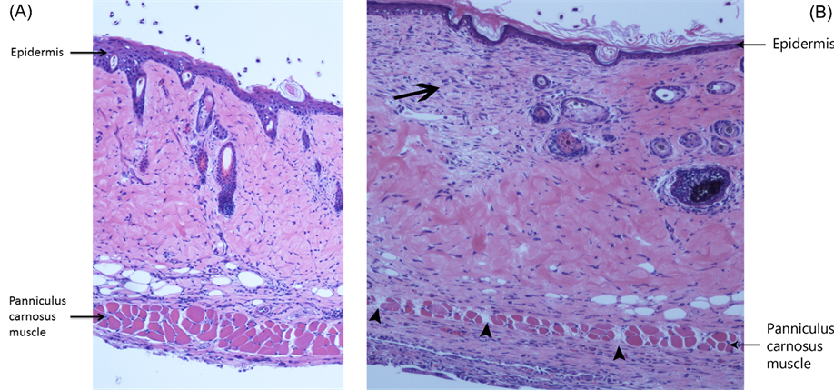
Figure 3. Flap histopathology. (A) Photomicrograph of the distal region of a porous implant flap at Day 10. Note the regenerating epidermis and viable panniculus carnosus muscle (Hematoxylin and eosin stain, 100× magnification); (B) Hematoxylin and eosin stain (100× magnification) of corresponding region of nonporous implant flap at Day 10 revealing focal dermal necrosis (arrow) and scattered panniculus muscle bundle necrosis (arrowheads).
Laser speckle imaging demonstrated significant spatial and temporal differences in perfusion between porous and nonporous implant flaps. In both groups, progressive increases in flap perfusion were recorded in each ROI at Day 2. However, in the nonporous implant mice, there was no further increase in perfusion in any ROI over the remaining study period. At Day 10, the perfusion of the distal (caudal ROI) nonporous implant flap did not even reach preoperative values suggesting impaired revascularization as a result of lack of engraftment due to the nonporous barrier. In contrast, in the porous implant group, there was a sustained increase in perfusion in all ROIs over time, with each day 10 ROI perfusion measurement significantly greater than the corresponding non- porous implant value indicating effective porous implant flap engraftment and revascularization (Figure 4 and Figure 5). In addition, the spatiotemporal perfusion values documented in porous implant mice were comparable to values previously reported in mice without implants [13] [14] .
3.4. Flap Vessel Count and Vascular Surface Area Analysis
To localize and quantify the microvasculature responsible for the spatiotemporal changes in implant flap perfusion, CD-31 immunostaining of endothelial identity and digital image analysis of comparative histologic sections were utilized to determine flap vessel count and vascular luminal cross-sectional surface area. Control back skin vessel counts and vascular surface area estimates were determined in an unoperated group of mice (n = 5), and laser speckle contrast examination of this unoperated or control group demonstrated equivalent perfusion compared to the preoperative perfusion values of both implant groups.
By Day 10, there were significant differences in vessel count and surface area between groups, with the values recorded in porous implant flaps higher than values in nonporous flaps (Figure 6). Moreover, quantification of the microvasculature and its anatomic localization provided an explanation for the changes in implant perfusion demonstrated by laser speckle contrast imaging. New vessel growth or neovascularization from the recipient paraspinal muscle vasculature into the caudal or distal flap through the implant pores as well as dilatation of existing cranial and central region vessels was responsible for porous implant flap revascularization and viability. Conversely, prevention of flap engraftment to the underlying paraspinal muscle bed by the nonporous implant resulted in inhibition of distal neovascularization and limited dilatation of proximal flap vasculature (Fig- ure 6, Figure 7).
3.5. Flap Macrophage Quantification and Localization
Control and Day 10 flap tissue sections were examined for the immunochemical identification of a macrophage-

Figure 4. Laser speckle perfusion imaging. (A) Quantitative laser speckle perfusion versus time of nonporous implant flaps (n = 5) demonstrating the gradient of ischemia between flap ROIs and no further increase in perfusion beyond Day 2; (B) Laser speckle perfusion images of nonporous implant flap at Day 10. The color scale illustrates variations in perfusion from maximum (red) to minimum (blue). Flap boundaries are outlined by arrowheads and distal flap ulcer by arrow. Note the lack of distal perfusion in the planar image on the left. A 3D surface plot (right) was created from matrix data with surrounding floor (black) set to average preoperative perfusion to illustrate flap changes relative to the unoperated state. Note the high perfusion of the ulcer site due to exposed paraspinal muscle (recipient bed) with known high baseline perfusion [10] . Also, note that select regions of flap perfusion do not return to baseline values (region below floor).
specific cell surface molecule to investigate changes in innate immune cell number and location associated with implant flap revascularization. F4/80 is a widely used mouse macrophage antigenic marker that is constitutively expressed during murine development and throughout adult life, and is absent on neutrophils [15] . In unoperated or control myocutaneous tissues, macrophages were sparsely located in the dermis, subcutaneous fat, and panniculus muscle and its investing fascia. At Day 10, in porous implant flaps, there was a significant increase in

Figure 5. (A) Quantitative laser speckle perfusion versus time of porous implant flaps (n = 5) demonstrating sustained perfusion in all ROIs over time with Day 10 ROI perfusion values significantly greater than corresponding nonporous implant values (*P < 0.05 versus nonporous implant, compare to Figure 4(A)); (B) Laser speckle perfusion images of porous implant flap at Day 10 demonstrating functional revascularization of the distal flap. Note the markedly increased perfusion in all regions of the flap (compare to Figure 4(B)).
macrophage number compared to control and nonporous implant tissues. Mononuclear cells were localized to pore site granulation tissue and flap panniculus muscle and dermis in perivascular locations. In contrast, macrophages present in the nonporous implant mice were predominantly localized to the recipient bed paraspinal musculature beneath the nonporous implant (Figure 8).
4. Discussion
In this study, we fabricated silicone implants with control of scale via the simple and inexpensive technique of projection microstereolithography. Laser speckle contrast imaging accurately documented graded wound ische-

Figure 6. Flap vascular quantification. (A) Quantitative vessel count of unoperated mouse back myocutaneous tissue (control) and proximal and distal regions of implant flaps at Day 10 (*P < 0.05 versus control; **P < 0.05 versus control and distal nonporous implant flap); (B) Quantitative vascular surface area estimate of control and proximal and distal regions of implant flaps at Day 10 (*P < 0.05 versus control; **P < 0.05 versus control and proximal and distal nonporous flap).
mia and functional revascularization of porous implant myocutaneous flaps. Immunohistochemical identification of endothelium confirmed porous implant flap revascularization resulted from dilatation of existing proximal flap vasculature (arteriogenesis) and new vessel growth from the recipient bed (angiogenesis) into the distal region of the flap through the implant pores. Histopathology demonstrated monocyte infiltration of porous implant flaps with macrophage localization to pore site granulation tissue and flap neovasculature. A bioinert implant was chosen as a nondegradable physical barrier with controlled thickness, pore size, and spacing to investigate the significance of spatially-focused engraftment or recipient site-flap contact on local ischemia and functional revascularization. The porous implant architectural specifications were chosen because most cells within the body are found no more than 100 - 200 µm from the nearest capillary, this distance allowing sufficient diffusion of oxygen, nutrients, and waste products to support and maintain viable tissue [16] .


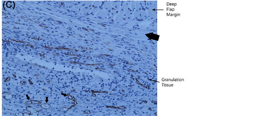
Figure 7. Flap vascular anatomy and localization. (A) Photomicrograph of Day 10 proximal porous implant flap demonstrating markedly enlarged proximal vessels (arrows) in dermis and granulation tissue. For comparison, arrowheads depict vessels of preoperative size (CD-31 immunostain, endothelium stains brown; 100× magnification); (B) High magnification (200×) image of CD-31 immunostained Day 10 porous implant flap illustrating granulation tissue neovascularization through an implant pore (vessels denoted by arrows); (C) Histologic section of Day 10 nonporous implant flap demonstrating recipient bed new vessel growth (arrows) beneath the nonporous implant (site of implant marked by thick arrow) with inability to penetrate the flap due to the nonporous barrier.


Figure 8. Flap macrophage quantification and localization. (A) F4/80 protein maximal fluorescent intensity (MFI) of unoperated mouse myocutaneous tissue (control) and porous and nonporous implant flaps (*P < 0.05 versus control and nonporous flap); (B) Histologic section of Day 10 porous implant flap stained with F4/80 primary antibody (100× magnification) demonstrating macrophage presence (brown) at pore site granulation tissue and panniculus muscle and dermis in perivascular locations (vessels denoted by arrows); (C) Histologic section of Day 10 nonporous implant flap (F4/80 immunostain, 100× magnification) illustrating macrophages primarily localized to the recipient bed granulation beneath the nonporous implant (thick arrow denotes position of implant).
Arteriogenesis is defined as the structural enlargement by growth of pre-existing arteriolar connections into true collateral arteries [17] . Collateral arteries can rapidly increase their lumen size by vessel fusion and directed endothelial cell migration, thus increasing the capacity to carry blood to ischemic regions [18] . Angiogenesis is defined as sprouting of pre-existing resident endothelial cells to form neovessels [2] .
In contrast to angiogenesis, which is dominated by a single growth factor, vascular endothelial growth factor (VEGF), arteriogenesis relies on a complex interplay of many growth factors, cytokines, different cell types, a multitude of proteolytic enzymes, and persistent pulsatile perfusion [19] [20] . Tissue ischemia/hypoxia is required for angiogenesis, but not for arteriogenesis, which is initially governed by physical forces that activate the endothelium of pre-existing arterioles [21] .
Macrophages are not just participants, but coordinators of early wound healing. They are among the first cells transported to the wound site via the circulation, and function in the inflammatory stage of wound healing to mediate the passive immune response and initiate arteriogenesis and delay the onset of angiogenesis [22] . In the following proliferative phase, macrophages appear to encourage angiogenesis by the production of proangiogenic factors, and by the mechanical facilitation of anastomosis by chaperoning direct contact between neighboring endothelial tip cells [23] . It is unclear whether these varied roles of macrophages are performed by different subpopulations of monocytes, or whether they represent evolving functions within a constant population [14] .
Using PµSL, we plan to design implants with variations in pore diameter, spacing, and location to precisely control myocutaneous flap engraftment or its direct contact with recipient bed. For example, by fabricating an implant with distal pores and no proximal pores, we can determine if cephalad flap engraftment is required for proximal arteriogenesis or this is a compensatory collateral response due to prolonged distal ischemia best stu- died with an implant with proximal pores and no distal pores. Using laser capture microdissection techniques, we plan to examine differences in endothelial and macrophage gene expression at precise flap locations and at pore sites in hopes of gaining a better understanding of the cellular and molecular microenvironment of flap engraftment, inosculation, and neovascularization.
References
- Isner, J.M. (2000) Tissue Responses to Ischemia: Local and Remote Responses for Preserving Perfusion of Ischemic Muscle. Journal of Clinical Investigation, 106, 615-625. http://dx.doi.org/10.1172/JCI10961
- Carmeliet, P. (2003) Angiogenesis in Health and Disease. Nature Medicine, 9, 653-662. http://dx.doi.org/10.1038/nm0603-653
- Adams, R.H. and Alitalo, K. (2007) Molecular Regulation of Angiogenesis and Lymphangiogenesis. Nature Reviews Molecular Cell Biology, 8, 464-475. http://dx.doi.org/10.1038/nrm2183
- Van Royen, N., Piek, J.J., Schaper, W., et al. (2010) A Critical Review of Clinical Arteriogenesis Research. Journal of the American College of Cardiology, 55, 19-35.
- Walker, A. and Gerhardt, H. (2011) Endothelial Development Taking Shape. Current Opinion in Cell Biology, 23, 676-685.
- Schechner, J.S., Crane, S.K. and Wang, F. (2003) Engraftment of Humanized Skin Equivalents. The FASEB Journal, 17, 2250-2261. http://dx.doi.org/10.1096/fj.03-0257com
- Phng, L.K., Stanchi, F. and Gerhardt, H. (2013) Filopodia Are Dispensable for Endothelial Tip Cell Guidance. Development, 140, 4031-4040. http://dx.doi.org/10.1242/dev.097352
- Muskin, J. and Ragusa, M. (2010) Three-Dimensional Printing Using a Photoinitiated Polymer. Journal of Chemical Education, 87, 512-514. http://dx.doi.org/10.1021/ed800170t
- Miller, J.S., Stevens, K.R., Yang, M.T., et al. (2012) Rapid Casting of Patterned Vascular Networks for Perfusable Engineered Three-Dimensional Tissues. Nature Materials, 11, 768-774. http://dx.doi.org/10.1038/nmat3357
- McGuire, P.G. and Howdieshell, T.R. (2010) The Importance of Engraftment in Flap Revascularization: Confirmation by Laser Speckle Perfusion Imaging. Journal of Surgical Research, 164, e201-e212. http://dx.doi.org/10.1016/j.jss.2010.07.059
- Gopinath, D., Kumar, M.S. and Selvaraj, D. (2005) Pexiganan-Incorporated Collagen Matrices for Infected Wound Healing Processes in Rat. Journal of Biomedical Materials Research, 73, 3320-3330.
- Leahy, M.J., Enfield, J.G. and Clancy, N.T. (2007) Biphotonic Methods in Microcirculation Imaging. Medical Laser Application, 22, 105-125. http://dx.doi.org/10.1016/j.mla.2007.06.003
- Howdieshell, T.R., McGuire, L., Maestas, J., et al. (2011) Pattern Recognition Receptor Gene Expression in Ischemia- Induced Flap Revascularization. Surgery, 150, 418-428. http://dx.doi.org/10.1016/j.surg.2011.06.037
- Khan, B., Rangasamy, S., McGuire, P.G. and Howdieshell, T.R. (2013) The Role of Monocyte Subsets in Myocutane- ous Revascularization. Journal of Surgical Research, 183, 963-975. http://dx.doi.org/10.1016/j.jss.2013.02.019
- Taylor, P.R., Martinez-Pomares, L. and Stacey, M. (2005) Macrophage Receptors and Immune Recognition. Annual Review of Immunology, 23, 901-923. http://dx.doi.org/10.1146/annurev.immunol.23.021704.115816
- Jain, R.K., Au, P., Tan, J., et al. (2005) Engineering Vascularized Tissue. Nature Biotechnology, 23, 821-833. http://dx.doi.org/10.1038/nbt0705-821
- Heil, M., Eittenmuller, I., Schmitz-Rixen, T., et al. (2006) Arteriogenesis versus Angiogenesis: Similarities and Differences. Journal of Cellular and Molecular Medicine, 10, 45-60. http://dx.doi.org/10.1111/j.1582-4934.2006.tb00290.x
- Udan, R.S., Vadakkan, T.J. and Dickinson, M.E. (2013) Dynamic Responses of Endothelial Cells to Changes in Blood Flow during Vascular Remodeling of the Mouse Yolk Sac. Development, 140, 4041-4050. http://dx.doi.org/10.1242/dev.096255
- Schaper, W. and Scholz, D. (2003) Factors Regulating Arteriogenesis. Arteriosclerosis, Thrombosis, and Vascular Biology, 23, 1143-1155. http://dx.doi.org/10.1161/01.ATV.0000069625.11230.96
- Schaper, W. (2009) Collateral Circulation: Past and Present. Basic Research in Cardiology, 104, 5-20. http://dx.doi.org/10.1007/s00395-008-0760-x
- Garcia-Cardena, G., Comander, J., Anderson, K.R., et al. (2001) Biomechanical Activation of Vascular Endothelium as a Determinant of its Functional Phenotype. Proceedings of the National Academy of Sciences of the United States of America, 98, 4478-4485. http://dx.doi.org/10.1073/pnas.071052598
- Stefater, J.A., Rao, S., Bezold, K., et al. (2013) Macrophage Wnt-Calcineurin-Flt1 Signaling Regulates Mouse Wound Angiogenesis and Repair. Blood, 121, 2574-2578. http://dx.doi.org/10.1182/blood-2012-06-434621
- Fantin, A., Viera, J.M. and Gestri, G. (2010) Tissue Macrophages Act as Chaperones for Vascular Anastomosis Down- stream of VEGF-Mediated Endothelial Tip Cell Induction. Blood, 116, 829-840. http://dx.doi.org/10.1182/blood-2009-12-257832
NOTES

*Corresponding author.