Modern Mechanical Engineering
Vol.09 No.03(2019), Article ID:95683,7 pages
10.4236/mme.2019.93006
Coupling for Parallel Non-Collinear Shafts
Ricardo Chicurel1, Gabriel Ascanio2*
1Instituto de Ingenieria, Universidad Nacional Autonoma de Mexico, Mexico City, Mexico
2Instituto de Ciencias Aplicadas y Tecnologia, Universidad Nacional Autonoma de Mexico, Mexico City, Mexico

Copyright © 2019 by author(s) and Scientific Research Publishing Inc.
This work is licensed under the Creative Commons Attribution International License (CC BY 4.0).
http://creativecommons.org/licenses/by/4.0/


Received: August 9, 2019; Accepted: August 27, 2019; Published: August 30, 2019
ABSTRACT
A novel coupling for two parallel shafts with non-collinear axes has been developed and used in a cycloidal transmission with magnetic gears. Such a coupling has been designed as an alternative to traditional couplings to transmit the rotation from the orbiting gear to the output shaft. The driving shaft transmits a couple consisting of two equal and opposite forces to a central element which, in turn, transmits the same couple, also consisting of two equal and opposite forces to the driven shaft. This novel coupling was successfully used instead of a traditional coupling resulting in, not only a smother operation, but also a more efficient power transmission.
Keywords:
Coupling, Cycloidal Transmission, Magnetic Gears

1. Introduction
Sometimes it is required to transmit rotary motion from one shaft to another that has a parallel offset and angular misalignment with respect to the first one. Although, misalignment is commonly observed in parallel coupling, such a phenomenon has been scarcely investigated. Some attempts are reported in the literature aiming to understand the effect of parallel offset and angular misalignment on power loss and vibrations [1] [2] . Some others analyzed numerically parallel misalignment of shaft rotor bearing systems [3] [4] . On the other hand, a Harmonic analysis of shaft rotor bearing systems with rigid coupling was performed using FEA [5] . Results were experimentally validated with a spectrum analyzer finding that misalignment has an obvious adverse effect on the rotor stability, particularly at low speed range. Parallel offset is the case, for example, in a cycloidal gear speed reducer where an orbiting gear having a fast-circular translational motion superimposed on a slow rotation, must transmit the slow rotation to an output shaft. To filter out the translational motion, the coupling that is generally used consists essentially of a disk of the output shaft with pins that penetrate into holes of the orbiting gear, where the radius of the holes is equal to the radius of the pins plus the eccentricity between the input and output shafts. An inversion of such a coupling results when one shaft is fixed preventing the rotation of another one but allowing its circular translation. Such is the case in scroll pumps, where the impeller is coupled in such a manner to a stationary member. The Oldham coupling, described, for example in ref [6] , provides a classic solution to the connection of offset shafts. The power loss associated with its sliding flat surfaces and its intolerance of angular misalignment is its main disadvantage. Variants of the Oldham coupling are described in patents [7] [8] . In the coupling described in this paper, the forces are transmitted between its components by contact between ball bearings and flat surfaces so no sliding occurs. Also, all forces are coplanar and only a couple, but no resultant force, is transmitted between components.
2. Description of Coupling
There are two versions of the coupling, depending on a central element, which is either a cross or a grooved plate. This central element is flanked by two lateral flanges, each keyed to one of the two shafts to be coupled together. On each flange, a number of cantilevered ball bearings are mounted; four in the case of the cross type coupling and two in the case of the grooved plate. Figure 1 shows the exploded views of the two types of the coupling.
As shown in Figure 1(a), a pair of bearings of a flange ride on tracks of one arm of the cross while the other pair of bearings ride on tracks of the opposite arm. Thus, the relative motion of the cross with respect to each flange is rectilinear, these two rectilinear motions being perpendicular to one another. The other type of coupling, shown in Figure 1(b), has a central plate with four radial grooves spaced at 90˚. The two bearings of a flange penetrate two opposite grooves and the two bearings of the other flange penetrate the other two grooves. The width of the grooves is slightly greater than the bearing diameters so that the bearings may roll freely on the grooves’ internal surfaces. In both types of couplings, the central element, cross or grooved plate, is confined to maintain a fixed distance from either flange by means of bearing confining shoulders. Clearly, the two types of couplings are kinematically equivalent to one another. A variant of the grooved plate is depicted in Figure 2. Instead of two pairs of grooves in alignment, there are two pairs of offset parallel grooves, an arrangement which may be made more compact.
Figure 3(a) is a diagram of a cross element showing bearings 1 - 4, from one flange, and bearings 5 - 8 from the other flange. The flanges, which are not shown, are designated A and B, respectively. A is on the front side and B on the back side of the cross. It is assumed that a clockwise moment, M, is being transmitted from flange A to the cross. This moment results from equal and opposite forces acting at the points of contact of bearings 1, 2 on the vertical arms of the
 (a)
(a)
 (b)
(b)
Figure 1. (a) Cross plate coupling; (b) Grooved plate coupling.

Figure 2. Variant of the grooved plate.

Figure 3. (a) Diagram of the cross element; (b) Motion of the cross.
cross. No forces are being transmitted by bearings 3, 4, as indicated by exaggerated gaps shown where these bearings would contact the cross. For equilibrium of the cross, a counterclockwise moment of equal magnitude, M, must be transmitted to the cross from flange B by contact between bearings 5, 6 and the horizontal arms of the cross. No forces are being transmitted by bearings 7, 8, as indicated again by gaps where they would contact the cross. A patent covering the two versions of the coupling has been applied for [9] .
3. Use of Coupling in a Cycloidal Transmission
As mentioned earlier, cycloidal speed reducers incorporate a coupling to transmit rotation between the orbiting gear and an output shaft. One such reducer has been equipped with a cross type of coupling previously described. This speed reducer has magnetic gears and is one of three that share a patented feature [10] [11] consisting of an orbiting gear unrestrained in the radial direction so that it is magnetically attracted to the fixed gear against which it bears and on whose internal surface it rolls, contrasting with the usual design in which the two magnetic gears are separated by a gap. The original design of this speed reducer included a traditional coupling consisting of a disk of the output shaft with six pins that penetrate holes in the orbiting gear, as described in the introduction. A limit on the maximum torque that can be transmitted to the output shaft is reached when the orbiting gear loses contact with the fixed gear because the forces from the pins act to separate the two gears. This limitation was removed when the original coupling was substituted by the cross type due to the fact that the latter can only transmit a couple, but no resultant force. A noticeably smoother operation was observed with the new coupling when applying torque by hand. The improvement with respect to torque capacity will be the object of tests being planned at this time.
Figure 4 is a photograph of the partially disassembled speed reducer showing the cross-type coupling.
4. Power Loss in Coupling
Because loads between moving parts are transferred in this coupling by rolling rather than by sliding action, the power loss is very small. Following is an analysis for the estimation of such loss.
Although the analysis is valid for either version of the coupling, for clarity in the argument the cross type of coupling will be assumed. Let M be the moment transmitted by the coupling and L the length of the longer side of the rectangle formed by the centers of the four ball bearings of a lateral flange. Then the normal force, P, being transmitted by the each of the two active bearings of a flange, is given by
, (1)
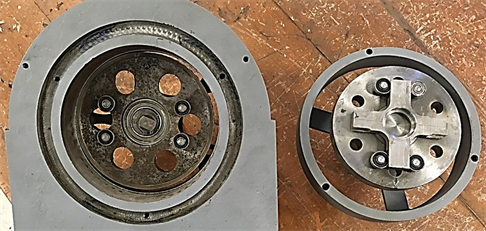
Figure 4. Partially disassembled speed reducer.
where the friction forces between the bearings and the surfaces on which they roll were considered negligible.
It is apparent that, if M is constant, P also remains constant as the shafts rotate. The diagram of Figure 3(b) is useful for visualizing the motion of the cross. The center of the cross is labeled “A”, and the axes of the arms extend from “B” to “C” and from “D” to “E”. O1 and O2 represent the axes of the shafts. Let the eccentricity . Now, angle O1AO2 is a right angle and remains so as the shafts rotate. This implies that the locus of A is a circle having a diameter e. Assuming that the shafts and cross have a clockwise rotation, as A advances from O1 to O2, the cross will execute a 900 rotation and BAC will go from a horizontal to a vertical alignment, and the active bearings will have rolled a distance e. The power loss per revolution consists of the loss due to rotation of the bearings plus the loss due to their rolling along the arms of the cross. The first of these may be estimated by using a friction coefficient for ball bearings [12] , f = 0.0015, resulting in a frictional torque
, (2)
where d is the shaft diameter for the bearing. Then, to overcome this torque, a friction force T1/(D/2), where D is the outside bearing diameter, is developed at the contact between the bearing and the cross surface. The rolling friction coefficient is assumed to be in the range 0.005 to 0.01 [13] . Using the higher value for a conservative estimate, the total friction force is
(3)
As explained before, each active bearing rolls a distance e each quarter of a revolution. Thus, the sum of the distances rolled by the four active bearings (two per flange) during one revolution, is 4 × 4e. Multiplying this displacement by the friction force given by Equation (1) yields the energy loss per revolution. Then, dividing by the transmitted energy per revolution, 2πPL, and multiplying by 100%, one obtains the percent power loss:
(4)
For the speed reducer and coupling mentioned in the previous paragraph:
e = 3 mm, L = 84 mm, d = 7 mm, D = 19 mm, resulting in a power loss, P.L. = 0.096% or, equivalently, an efficiency of 99.9%.
This is indeed an outstanding finding considering that, both misaligned shafts and parallel non-collinear shafts induce high radial forces resulting in less energy transferred from one shaft to the other one [2] .
5. Conclusion
A novel coupling for two parallel shafts with non-collinear axes has been described. The driving shaft transmits a couple consisting of two equal and opposite forces to a central element which, in turn, transmits the same couple, also consisting of two equal and opposite forces to the driven shaft. The magnitudes of the forces only depend on the magnitude of the transmitted moment. There is no sliding between moving parts, so transmission of forces occurs only at rolling contacts with minimal power loss. This type of coupling was tried in a cycloidal transmission with magnetic gears, in substitution of a traditional coupling, to transmit the rotation from the orbiting gear to the output shaft. After the substitution, a smother operation was observed. Also, it is important to point out that radial forces induced by non-collinear shafts were reduced with the coupling proposed in this work, so that the efficiency was noticeably increased.
Acknowledgements
The financial support from DGAPA-UNAM through grant IT101117 is highly acknowledged. Authors thank to Mr. David Santoyo García and Luis E. Calderon for the technical support provided.
Conflicts of Interest
The authors declare no conflicts of interest regarding the publication of this paper.
Cite this paper
Chicurel, R. and Ascanio, G. (2019) Coupling for Parallel Non-Collinear Shafts. Modern Mechanical Engineering, 9, 57-63. https://doi.org/10.4236/mme.2019.93006
References
- 1. Tuckmantel, F.W.S., Schoola, C.G. and Cavalca, K.L. (2019) Flexible Disc Coupling Model in Rotating Shafts. In: Cavalca, K. and Weber, H., Eds., Proceedings of the 10th International Conference on Rotor Dynamics—IFToMM. Mechanisms and Machine Science, Vol. 61, Springer, Cham, 502-517. https://doi.org/10.1007/978-3-319-99268-6_35
- 2. Sawalhi, N., Ganeriwala, S. and Tóth, M. (2019) Parallel Misalignment Modeling and Coupling Bending Stiffness Measurement of a Rotor-Bearing System. Applied Acoustics, 144, 124-141. https://doi.org/10.1016/j.apacoust.2017.07.022
- 3. Pennacchi, P., Vania, A. and Chatterton, S. (2012) Nonlinear Effects Caused by Coupling Misalignment in Rotors Equipped with Journal Bearings. Mechanical Systems and Signal Processing, 30, 206-322. https://doi.org/10.1016/j.ymssp.2011.11.020
- 4. Hujare, D.P. and Karnik, M.G. (2018) Vibration Responses of Parallel Misalignment in Al Shaft Rotor Bearing System with Rigid Coupling. Materials Today: Proceedings, 5, 23863-23871. https://doi.org/10.1016/j.matpr.2018.10.178
- 5. Lu, X., Zhang, J.H., Ma, L., Wang, J., Wang, J. and Dai, H.W. (2017) Effects of Misalignment on the Nonlinear Dynamics of a Two-Shaft Rotor-Bearing-Gear Coupling System with Rub-Impact Fault. Journal of Vibroengineering, 19, 5960-5977. https://doi.org/10.21595/jve.2017.18476
- 6. Ham, C.W. and Crane, E.J. (1948) Mechanics of Machinery. Mc Graw Hill Book Company, Inc., New York.
- 7. Suss, J. (2013) Scroll Compressor Having an Anti-Rotational Arrangement including an Axial Bearing. U.S. Patent No. 6,666,669.
- 8. Smerud, S.J., Swaney, B.J. and Rood, J.A. (2017) Oldham Coupling with Enhanced Key Surface in a Scroll Compressor. U.S. Patent No. 9,765,784.
- 9. Chicurel, R., Ascanio, G. and Calderón, L.E. (2018) Acoplamiento para flechasparalelas no colineales [Coupling for Parallel, Non-Collinear Shafts]. Mexican Patent Application MX/2018/006351.
- 10. Chicurel, R., Vázquez, L.A. and Ascanio, G. (2015) Cycloidal Transmissions. U.S. Patent No. 8,979,698.
- 11. Chicurel, R. (2013) Cycloidal Magnetic Gear Speed Reducer. Modern Mechanical Engineering, 3, 147-151. https://doi.org/10.4236/mme.2013.34021
- 12. American Roller Bearing Company. https://www.amroll.com/friction-frequency-factors.html
- 13. The University of Utah Engineering. http://www.mech.utah.edu/~me7960/lectures/Topic8-LinearRollingBearings.pdf