Received 10 January 2016; accepted 23 February 2016; published 26 February 2016

1. Introduction
Image deformation has proven to be a powerful tool for image editing. There are many applications from animation, morphing, to image correction and recognition. In the last two decades, a considerable amount of research has been directed towards image deformation. The classical method for image deformation is obtained by linear combination of affine transformations; see [1] [2] . In the methods, the user needs a few handles and manipulates them to control the shape. The energy-based or variational-based methods are the powerful and popular way to image distortion. The approaches produce warps by minimizing a functional with some roughness criteria, such as [3] [4] . The techniques are always not easy to implement and mostly cost greater computation in the post-time. Free-form deformation methods (see [5] ) and skeleton-based techniques (see [6] ) distort the shapes by manipulating the space in which they are embedded. They are very efficient in computation and easier to be implemented, but they have not enough in providing convenient or intuitive tools for the user.
We want to propose here a new attempt for image deformation. The proposed method is intuitive, and easy to manipulate without tedious landmarks. We view image deformation as a result of a force field that is exerted on the input image. If the pixels of an image are regarded as small particles, under forces, the particles should be moved and form new shapes. Here we want to simulate the distortion under external forces and extend it to image warping. We know that the Newton’s Second Law of Motion (NSLM) links the force and displacement. Thus, through NSLM, we can infer the new position for each pixel by a given force field. We achieve the distortion in the form of a partial differential equation (PDE). PDE-based methods are widely applied in the image filtering, see [7] -[10] . The typical PDE-based approaches deform a given image with a specially-designed PDE, and obtain the desired result as the solution of this PDE with the input image as initial conditions. In the form of a PDE, one can model the images in a continuous domain, and control the evolving process more precisely to avoid over processing. In this paper, we present a new technique for image deformation. In the new method, we can customize the region of interest (ROI) to restrict distort in a desired region, while leaving the others without modification. Unlike the classical PDE-based filtering models, we attempt the useful tool to evolve an image on the coordinates or displacement, not on the value of intensity or the vector of color.
2. Deformation by User-Defined Force Fields
2.1. Image Deformation under Forces
Let  be the force exerted on the pixel located at
  at t time. According to NSLM, the net force on an object is equal to the rate of change of its linear momentum:
 ,
,
where m is the mass of the body, and  is instantaneous velocity. As the position is the prime consideration in image deformation, we ignore the differences between pixels and regard all the pixels have a constant-mass m. Notice that the velocity can be computed as the derivative of the displacement vector
 , then we get
 , (1)
, (1)
where  denotes the displacement of pixel
  at t time. By the Equation (1), we can pass forces to image pixels and drive them as we desire. It allows us to apply it directly to image deformation by a specially-designed force field. Once the smooth force field is figured out, the image will be deformed continuously and naturally by the equation.
To solve the simple second-order PDE equation, we can certainly suppose that the initial position of each pixel is as that of the input image, and the velocity state is still. Therefore, we can calculate the new position for each pixel by
 (2)
(2)
However, the deformation driven by Equation (2) will leave some blanks on the image at each iteration, meanwhile; some coordinates perhaps contain more than one pixel. The two cases are inevitable. For the former, to remove these empty dots, there are many filters can be used. For example, we can use the classic average or median filtering, or the more effective methods, such as the inpainting method [11] . To lessen the disadvantage of this case, we can reduce time step and remove the blanks in time at each iteration. For the latter, if the deformation is ongoing, we reserve all the overlapped pixels for the next motion; else we must discard some of them, and only reserve one of them.
2.2. Design of Force Fields
Here we design two types of force fields to simulate the process of object distortion under external forces. One is for image stretching/squashing, and another for image twisting.
One can imagine how to stretch a thin piece of pizza. Suppose the pizza sticks on the table. We hold one position (here we call the begin pixel), pull and move it slowly to another (called the end pixel), and then we get it. Forces around the two pixels are stronger than that of far away the two pixels, and the orientation of the force can regard as the same one. For the sake of simplicity, let  is constant with respect to time, i.e.,
 , for any
 ,
,
and considering smooth and natural deformations, we define such a vector field  as follows:
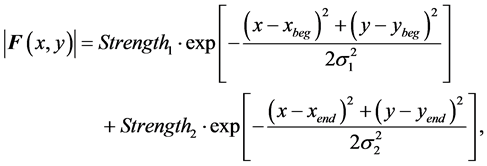
 ,
,
where the pixels ![]() and
and ![]() are the begin pixel and the end pixel, respectively. The parameters
are the begin pixel and the end pixel, respectively. The parameters ![]() and
and ![]() control, respectively, the scopes of deformation around the begin pixel and the end pixel, and the parameters
control, respectively, the scopes of deformation around the begin pixel and the end pixel, and the parameters ![]() and
and ![]() control the magnitude of force of the two pixels, respectively. In Figure 1, we show a force field which moving the pixel (130, 130) to the pixel (160, 160), and the corresponding deformed result. In this type of vector fields, we stop the distortion when the begin pixel is impelled to or
control the magnitude of force of the two pixels, respectively. In Figure 1, we show a force field which moving the pixel (130, 130) to the pixel (160, 160), and the corresponding deformed result. In this type of vector fields, we stop the distortion when the begin pixel is impelled to or
over the location of the end pixel.
Similarly, we also employ the following force fields for image twisting:
![]() ,
,
![]() ,
,
where ![]() and
and ![]() are, respectively, the center pixel and the rim pixel, which the two user-defined pixels are used to decide the central location and radius of twisting. In this type of force fields, we let the user decide when to stop the distortion.
are, respectively, the center pixel and the rim pixel, which the two user-defined pixels are used to decide the central location and radius of twisting. In this type of force fields, we let the user decide when to stop the distortion.
Sometimes we want to restrict the deformation in a region of interest. We can select a region in the source image by drawing a simple closed curve as shown in Figure 2(a). We zero the forces which are out of the region, and the forces within the region need to be modified to fulfill a smooth distort. In Figure 2(a), we show a user-defined region, and Figure 2(b) show the smoothed one. In the smoothed mask, the values range from 0 to 1. The brighter a pixel is, the closer the mask value tends to 1; and the more black a pixel is, the smaller the value is. This smooth mask can be obtained by a morphological operator. First, we flood-fill the region with white color, and next apply an erosion operator to it. After that, we compare the result between the last step, and then set a different value for the eroded pixels. Repeat doing erosion, at last we can obtain the faded mask.
3. Experimental Results
In the experiments, we implement the new deformation with C++ code in the platform of Windows 7. We have developed an intuitive and convenient tool which is available at http://wudging.ys168.com/.
In the experiments, we set the begin and end pixels, or the center and rim pixel, and the deformation region of interest by mouse clicking or drawing. To reduce the amount of blanks when deforming, and to fulfill a better fill-in, we suggest that the time step should not be too big. In this paper, we always set![]() . As the blanks are unavoidable, it is necessary to employ a suitable filtering algorithm for the removal of them. Considering the run time and effectiveness, we choose the average filter with
. As the blanks are unavoidable, it is necessary to employ a suitable filtering algorithm for the removal of them. Considering the run time and effectiveness, we choose the average filter with ![]() local windows. In these experiments, some of the input images are manipulated in continuous processes, and we found that the time of each deformation is not more than 1 seconds.
local windows. In these experiments, some of the input images are manipulated in continuous processes, and we found that the time of each deformation is not more than 1 seconds.
Figure 3 shows the Lena image and her deformed hat, one can see that the surrounding objects, such the rods in the northwest and east of the hat, have no warps, because we have restricted the deformation into a free-drawn region that only contains the hat. Figure 4 shows a deformed head. Additionally, by choosing a proper region of interest, we can deform the head without warping the eyebrows and the ears. Figure 5 shows a wilder ocean wave by setting the center and rim pixels with the restricted region; from the result, we can see the deformation is smooth and hardly perceptible. From Figure 6 and Figure 7, we can see more such examples.
In Figure 8, we show the proposed method can be applied to image correction. Usually, the texts of a book will be deformed when the book is open on the desk. The corrected result shows our method can be applied in such cases.
![]()
![]() (a) (b)
(a) (b)
Figure 2. Smooth mask for ROI. (a) An user-defined region; (b) the related mask.
![]()
![]() (a) (b)
(a) (b)
Figure 3. (a) Lena image, 512 × 512 in pixels; (b) her deformed hat.
![]()
![]() (a) (b)
(a) (b)
Figure 4. A deformed head. (a) Original image (331 × 300 in pixels) with the begin pixel (green) and the end pixel (red), and the regions of interest; (b) deformed image by two steps with the same parameters: Strength1 = Strength2 = 80, σ1 = σ2 = 100.
![]()
![]() (a) (b)
(a) (b)
Figure 5. A wilder ocean wave. (a) Original image (360 × 260 in pixels) with the landmarks, the center pixel (green), the rim pixel (red), and the region of interest; (b) deformed wave with the twisting force field: Strength = 100 and Iteration is 3.
![]()
![]() (a) (b)
(a) (b)
Figure 6. A deformed alarm-clock. (a) Original (965 × 1016 in pixels); (b) deformed.
![]()
![]() (a) (b)
(a) (b)
Figure 7. A lovely flower. (a) Original image (529 × 458 in pixels); (b) deformed flower.
![]() (a)
(a)![]() (b)
(b)
Figure 8. Removal of distortion. (a) A book is opening on the desk in the natural state. The picture is taken by a phone camera, (trimmed, 657 × 196 in pixels); (b) the corrected texts.
4. Conclusion
In this paper, we deform an image gradually and continuously using Newton’s Second Law of Motion. The new method is in the interactive mode and very convenient. From the experiments, the deformed result of the proposed technique is very smooth and natural.
Acknowledgements
This work was supported by the National Natural Science Foundation of China under 61561025 and 61562039.