1. Introduction
The growth mechanism of calcium fluoride—as product of ore minetalization or artificially grown crystals—depends on thermodynamic and crystal-chemical conditions of the surrounding medium. Both the crystal habit and crystallographic character of crystal faces can be changed in accordance with P-T mineralization conditions and solutions chemistry. It firmly established crystal transition from octahedral to cubic form via some more complex intermediate forms [1] . The habit of the real crystals is, as a rule, not geometrically regular that is due to irregularity in the mass-transport for supplying substance. One-directional supply has been proved to distort gradually the cubic crystal to mosaic block, rod-like or lamellar whereat the symmetry decreases, the habit becoming in some cases completely irregular.
The exact reconstruction of the existed thermodynamic and crystal-chemical conditions during the growth of CaF2 natural or artificial crystals appears as a challenging task since it would help the researchers to clarify the variety of interrelating factors that can influence considerably the crystal alterations during ore mineralization as well as during the application of both applied growing techniques—from melt and from vapor. The present paper accentuates just on vapour growth of CaF2 as much less explored technique for this type of artificial crystals [2] .
It is well-known that single CaF2 appears in many cases—a preferable optical medium for manufacturing optical elements appropriate to satisfy the fast increasing needs of large scale optics in deep ultra violet (UV), visible (Vis) and infrared (IR) spectral regions. Since the direct usage of natural fluoride for manufacturing thereof optical elements is strongly restricted due to impossibility, to be replaced by: being found sufficiently homogeneous large single crustals, showing minimum structural defects, it was approved that mined fluorite may be used as starting fluorspar after its transforming to sintered or polycrystalline precursors. On this ground different modifications of industrial growing techniques have been developed successfully during the last three decades [2] . Nevertheless, the latest very strict requirements of vacuum UV and UV-laser optics put increasing challenges before the growers as concerning the purity of starting fluorspar and final product as well as the cost price of the later. Here the Single Crystal Technology was thought as a promising method for enhancing significantly the yield of high-sized CaF2 crystals [3] .
Without comparable industrial effect but submitting several specific scientific issues, the vapour growth of CaF2 by using of fluorspar as starting material appears. Since in practical, any fluorspar contains definite amounts of mostly REs—as hardly removable impurities, a new modification of Bridgman-Stockbarger (BS) growing technique was developed. Its essence is in the usage of multicameral crucible with original construction, wherein several boules can be grown simultaneously from separated melts, while inhomogeneous substance is being crystallized from vapor phase in supersaturated peripheral crucible compartment [4] . In that way the REs’ contents in the grown boules can be substantially reduced at the expense of corresponding REs’ enrichment in the vapor grown substance. The efficiency of such technique depends on the ability of a given RE to form a stable fluoride composition, whose ionized molecules possess sufficiently higher evaporation rate compared to that of ionized molecules of the basic CaF2. The purification process is well-controlled by attaining a definite P-T equilibrium inside the crucible.
The present survey aims at experimental and theoretical investigation of the effects of all modes phase transformations in the described mode multicameral crucible, varying largely the P-T conditions, over the structure and properties of relevantly grown crystals/crystallite. This suggests, firstly, the determination of the triple point (t.p.) phase diagram of the used fluorspar that would allow being studied in details any quasi-equilibrium alterations during the proceeding mass-transport phenomena and related kinetic reactions. The longitudinal cross-sectional view of the grown crystallite would reveal how the crystal habit may change manner according to phase transformations mode. The results are anticipated to clarify the mechanisms and regularities that govern the processes and phenomena proceeding. This may increase the significance of growing single and mixed crystal fluoride compounds from vapor phase by modification and/or optimization of the applied technique on the base of reliable thermodynamic grounds. From geological point of view the results can promote model simulations of some mineral-genetic processes grounded on HV low-gravity emissions that could be thought being existed on the moon or other small sized space objects where similar conditions could whenever be existed.
2. Material, Methods and Apparatus
The starting material is prepared by using fluorspar containing several tens ppm in total RE elements with cerium being a prevalent one [5] .
The growing experiments are performed in BS type apparatus (Figure 1(a)), the furnace unit of which is con-
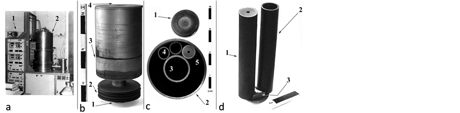
Figure 1. (a) Apparatus for crystal growing by BS method with furnace control panel assy (1) and growing chamber (2); (b) Multicameral graphite crucible with supporting tail-end (1), batch of separated heat-adjusting Mo-rings (2), cylindric body (3) and general cover with axially drilled channel (4); (c) Cross-section of multicameral crucible (2) with a central camera (3) and up to 9 peripheral inserts (4), covered with corresponding lids (1) and (5). Some of the lids can be taken away to accelerate the melt vaporization; (d) View of two peripheral inserts (1) and (2), in-between the bottom section of which a fluorspar vapour condensate in the PC, shaping a segment (3).
structed to provide a precise control over the thermal field configuration. The multicameral mode crucible is made by low porous, high purity graphite.
Its cameras represent several inner axial-symmetric inserts, which, after being loaded with grained purified fluorspar portions (or thereof made precursors), are put in a peripheral compartment (PC) with annular crosssection (Figure 1(b) and Figure 1(c)). The crucible “core” is a hollow tubular compartment, twice larger in diameter compared to inserts’ diameter, and is loaded with another portion of the same type fluorspar. The crucible cameras are loaded by weighed out portions of grained fluorspar (a grained fluorspar fraction +0.25 - 0.8 mm is selected), wherefrom weighed amounts are mixed carefully with 2.4 wt% PbF2 that has a scavenger’s effect during the heating stage, thus providing a removal—by chemical reactions—of mostly oxygen-containing contaminants [6] . The free spaces inside isolated cameras are connected to PC free space by parallel system of channels, drilled axially in corresponding cameras’ lids. An axial channel in the outer cover of the crucible connects its interior to the vacuum chamber ambient. The gas-permeability of the channels, depending on their diameter and length, may affect the proportion in-between the possible types of mass-transport mechanisms: Knudsen diffusion, normal diffusion or viscous flow. The partial and/or total effective gas-conductivities of such designed system of channels determine the established pressures inside the crucible at a given T-head imposed upon the molten substance.
The methodology consisted in providing an intensive bulk boiling in all isolated melts causing a high speed vaporization of different in mass%, but significant partitions from the molten portions in the cameras at controlled P-T conditions. This result in a fast supersaturation by fluorspar vapors of crucible interior, which initiates, during the slow crucible withdrawal towards the “cold” furnace zone with steep negative slope of T-profile, condensation or sublimation of fuorspar vapour upon the flat bottom surface of the PC, in-between nearly disposed therein inserts. Both processes lead to growth of crystallite enriched to those REs, the fluorides of which possess a sufficiently high vapour pressure to endure effective liquid to vapour phase transformation. Essentially, the experiments are implemented as combined, simultaneous crystal growing from melt (inside the cameras) and from vapor—in the PC. The final production represents a batch of parallel boules expectedly being homogeneous and with sufficiently high optical characteristics that may satisfy eventually the contemporary, mostly strict demands of VUVand UV-optics, whereas the PC sublimate, depending on the degree of its RE’s concentration, can be used approprately, for example to manufacture of selective light-shutters.
The vaporized quantities are calculated as differences between the initial and final gross weights of the loaded inserts. The vapour fluxes throughout the lids’ channels are estimated using the average time-dutation of the process.
The T-head upon the molten portions is varying up to 34 K (“low” head), from 35 to 160 K-“intermediate” head and above 160 K—“high” head. This way a sequence of physical-chemical and/or crystal-chemical processes is being initiated leading to shift in desorption/adsorption equilibrium, evaporation/vaporization by melt boiling, condensation, ionic replacements into fluorite lattice, melt and vapor crystallization (sublimation).
Longitudinally processed probes of the crystallized material are investigated by optical microscope in reflected and transmitted light, electron microscope and electron-transmission microscope. The used transmission electron microscope (TEM) Phillips EM 420 works with accelerating voltage of 100 kV. The needed specimens are prepared by the method of wet suspending after grinding in alcohol and deposition on a perforated carbon film with a thickness below 0.5 nm, mounted onto 3 mm diameter copper grid disks.
The spectral distribution of the optical transmission t is measured at room temperature on (2.0 ± 0.15) mmthick bi-side polished parallel plates within accuracy of ±0.3 nm in the spectral range 195 - 800 nm, using a Varian’s UV-VIS spectrophotometer Cary 100. The absorption coefficient, α, is calculated via Beer-Lamber’s formula α = d−1 ln(1/t) with d being the sample’s thickness. All samples are tested for internal stresses in polariscope/polarimeter PKS-250 U.4.1.
The total internal reflection of fine grinding probes is being measured by using of Evolution 300 UV-VIS Spectrometer of THERMA.
3. Results and Discussion
The condensation/sublimation of fluorite vapours is found to start on segmental areas between the particular inserts (Figure 1(d) and Figure 2(a)). At larger resolution it is seen each one segment is built up forming a basis representing pseudo-grained fluorite aggregate consisting in skeleton CaF2 small crystals whereupon one may suggest being condensed and crystallized several fluorite drops (Figure 2(b)). On the surface of thus formed basis, numbers of plate-like and acicular crystals are being grown selectively (Figure 2(c)).
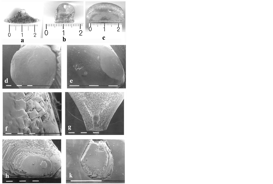
Figure 2. Optical microscope pictures of crystallized material in the PC of multicameral crucible, imposed 7 hours in HV at constant T-head, followed by 28 hours lasting crucible withdrawal with speed of 4 mm per hour in optimized furnace unit of BS apparatus. (a) Condensed and crystallized fluorspar vapour with segmental shape; (b) Condensed and crystallized fluorite drops; (c) Selectively grown plate-like and acicular fluorite crystals; (d) Fluorite drops, surrounded by deeper globules, connected by fine particles of graphite and fluorite; (e), (f) Different faceting of crystal faces for the condensed drops; (g) Equal in sizes pits on places found close to inserts’ external surface; (h) A stem-like single crystal with hexagonal crosssection, incorporated into a fluorite drop; (k) Scale up fragment of picture h.
The basis with height of ≈4 mm is shown in Figure 2(d), being built in light corns, surrounded by deeper globules with diameter of ≈1 mm, connected by fine particles of graphite and fluorite. The drops, sized between 4 and 10 mm, turn out clear, without any inclusions and defects. The smaller ones are found close to ideal sphere while the bigger ones represent oblate spheroids. The basic-drops boundary is manifested sharply, as the wetting angle between the sharp surface basic and the drops varies from 20 to 60 degrees of circle (measured using SEM photos). This suggests a large surface tension for condensing drops. Their faceting occur either with [111] crystal faces or with numbers of [110] or [100] rough teeth-like edges (Figure 2(e) and Figure 2(f)). In some cases these details are rounded due, more likely, to re-melting the crystallized substance and/or sublimation phenomena that is identified on Figure 2(g) where several equal in sizes pits are seen to appear on the places found close to inserts’ external surface. A case is also observed where a plane is faceting a drop (Figure 2(e)) that can consider an indication for slower crystal growth on (111)-direction as comparing (100)- and (110)-directions, owing to mass-redistribution from drop’s surface of the observed plane zone to the remaining part of the aggregate. In other case it is observed a stem-like single crystal with hexagonal cross-section grown on (111)-direction, incorporated into a fluorite drop (Figure 2(h)) where partial re-melting of crystal faces can explain the scale up view of the picture (Figure 2(k)). At this junction one may suppose the observed hexagonal single crystal has been grown before the condensation and crystallization of the surrounding drop to proceed.
Going further upwards the studied sample aggregate it is seen that from fluorite drops are grown numbers of needleand plate-like crystals, equal in sizes and orientation. Here some speculative suggestions as regards the nucleation mechanism could be made. In the case under consideration—as contrasted with the crystallization proceeding via (111)-faceting in the condensed drop—the crystallization of the stemand plate-like crystals proceeds on (100)- and (110)-directions with clearly visible rectangular and square cross-section (Figure 3(a), and Figure 3(b)).
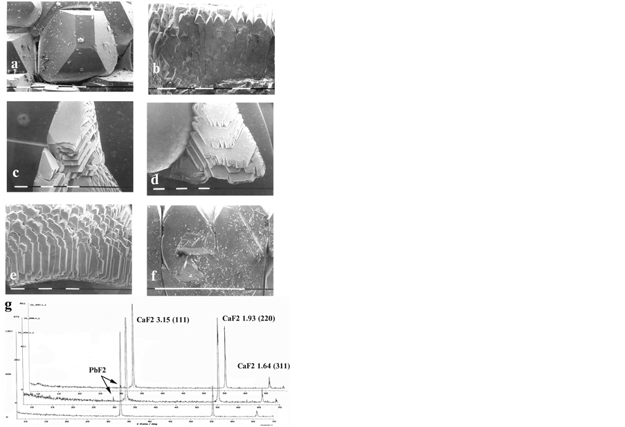
Figure 3. Longitudinal cross-sectional view in optical microscope of probes taken from the material crystallized in PC: (a), (b) Stemand plate-like crystals, crystallized on (100)- and (110)-directions with rectangular and square crosssections; (c), (d), (e) Crystal aggregates—packages of hexagonal plates with acute teeth-like tips; (f) Splitting and secondary selection for growing crystals; undermost—X-ray diagrams of three distinguished zones in the grown aggregates.
The orientation of these needleand plate-like crystals should inherit partially the drop’s matrix that bore a specific surface of the aggregates—packages of hexagonal plates with acute teeth-like tips (Figures 3(с)-(e)). It can be supposed a strong competition to proceed between thus growing single crystals in supersaturated by fluorspar vapor ambient. Owing to that, the growth of crystals, being they even insignificantly disoriented outside the general (110)- and (100)-directions, would be totally suppressed. Thence specific rounded off cavities arise between the needleand plate-like single crystals in the region of their expansion. Considerable effect gains as well the structural defects, causing splitting and secondary selection for growing crystals (Figure 3(f)).
The X-rays phase analysis of the three distinguished zones of grown fluorite aggregates shows that their stoichiomerty correspond to pure CaF2 without any X-raying peculiarities (Figure 3—undermost).
The electron diffraction analysis, performed by TEM, manifests the growth of needleand plate-like crystals on definite fluorite drop should be accompanied by its (111)-epitaxy related to (110)- and (100)-epitaxy for corresponding basic forms. The surface atomic layer should be modulated due to establishing radius for drop’s rounding that would cause splitting of the crystal lattice for growing on the drop crystals. These processes are identified on the electron-diffraction pictures as enlargement and splitting of the index reflection spots.
Three samples, thought relevant to different growth stages, are investigated by TEM analysis. In the sample corresponding to the first growth stage (primary vapour phase crystallization) the µm-sized crystals are observed (Figure 4(b)). The obtained selected area electron diffraction image (SAEDI) shows that the different particles actually are single-crystals. The point maximums are arc-like splited and the arcs (indicate with arrow) are curved at round 10˚ (Figure 4(a)). After multiple magnifications of the particles (Figure 4(c)), the diffraction contrast visualized nano-sized defect areas disorients up to 10˚, which coincides with the arc-like splitting of diffraction maximums.
In the sample, relevant to second growth stage, it is observed a drop-like crystal, round 1 cm in diameter, built from nm to µm separated mono-crystals (Figure 5(c) and Figure 5(d)). SAEDI shows the existence of satellite (indicate with arrow) reflexes, the disposition of which approves a perfect monocrystal structure (Figure 5(a)). The monocrystals are situated accidentally each by other and form polycrystal SAEDI where no proofs for texturization exist (Figure 5(c) and Figure 5(d)).
The sample from the third growth stage is present from microcrystals, grown on the crop-like crystal. Figure 6(a) shows the SAEDI from [112] direction, resultant from the micro-crystal on Figure 6(b).
It is seen that two satellite point maximums are situated at both sides of each main maximum at angle round 2˚. The particle morphology shows monocrystal (marked on Figure 6(b)), as (1) with [110] growth direction, development of the (131) and (311) crystal faces. One can observe and the second one crystal (marked on Figure 6(b) as (2) and enclosed within dotted lines), fused with the first one on (111) crystal face, and having the same growth direction, development of the same crystal faces. Round 2˚ fusion angle is being measured between the two crystals, which coincides with the angle between the satellite point maximums.
The analyzed view of SEM-microscopy pictures allows reconstructing the growth itself; it is started with slightly disoriented each other nano-crystals joined in microcrystals, which are oriented differently to the matrix, creating a thin layer. After differentiation of that thin layer, a drop-like polycrystal aggregate is built up, consisting of several, different in sizes perfect mono-crystals. Over them is growing up small-angle fused monocrystals due to the almost spherical matrix.
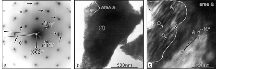
Figure 4. TEM analysis of probes prepared from crystal section growing during the first stage of the process. (a) SAEDI along [110] direction of area “а” from crystal (1) shown at (b); (b) Microcrystal (1) oriented at (110) plane; (c) Above eight as much higher magnification of area “а” from the crystal (1).
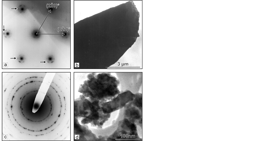
Figure 5. TEM analysis of probes taken from crystal section growing during the second stage of the process: (a) SAEDI along [111] direction of round area from crystal shown at (b); (b) Micro-crystal oriented at (111) plane; (c) Polycrystal SAEDI of round area from crystal shown at (d) microcrystals with grain-shaped structure.
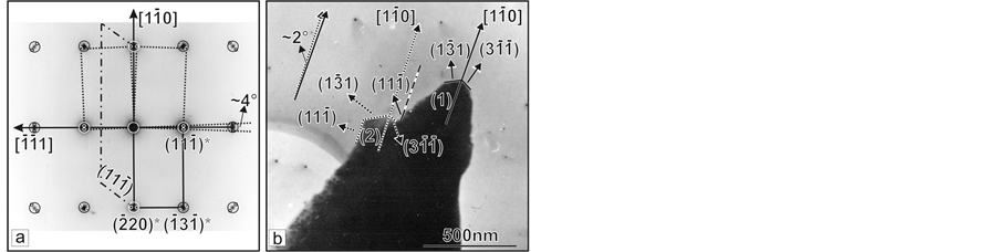
Figure 6. TEM analysis of probes taken from crystal section growing during the third stage of the process: (a) SAEDI along [112] direction of area а from crystal (1) shown at (b); (b) Microcrystal (1) oriented at (112) plane.
Spectrophotometric analysis (Figure 7) is performed using 4 samples, two of which (sample 1 and 2)—taken from boules, grown into different crucible inserts whereas the other two (sample 3 and 4)—from crystallized material after condensation/sublimation of fluorspar vapour in the peripheral crucible compartment during the same growing run. It is seen the spectra of samples 3 and 4, grown from the vapour phase, contain two clear bands which, according to literature [7] -[10] , can be attributed to absorption near 198 and 306 nm causes by 4f - 5d electron transitions in Ce3+. Nevertheless, the peaks’ positions of both samples are found being slightly shifted at 197.3 nm and 302.5 nm, respectively that could be attributed to bi-valent ionic replacement of Sr for Ca into fluorite lattice (strontium content in starting fluorite, identified varies within (0.03 - 0.05) wt% [11] ), and partial replacement of some Sr2+ by cluster formations of Ce3+ ions compensated by F−-interstitial [12] . Such replacement mechanism was proved being highly efficient for single alkali-earth host crystals [8] as well as for mixed calcium strontium fluoride system [11] .
It the same time, the spectra of samples 1 and 2 (grown from non-vaporized melts in crucible inserts) do not reveal any absorption bands that suggests, in practical, all Ce ppm-amount being efficiently removed from liquid to vapour phase and crystallized thereof aggregates. The absorption coefficient spectra for samples Nos. 1, 2 and 3 are close to each other along the whole visible spectral range, from 400 to 800 nm, manifesting a gradual de-
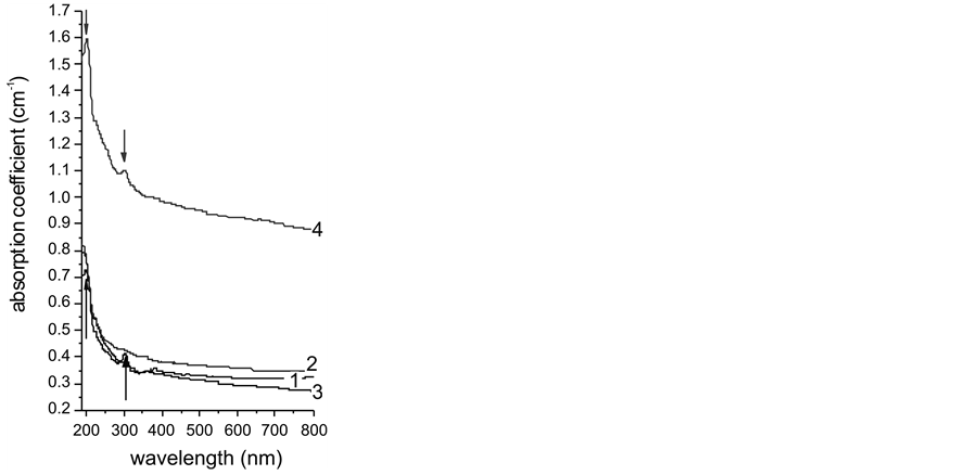
Figure 7. Optical absorption coefficient spectra of CaF2 single crystals grown in different crucible compartments from melt (samples 1 and 2) and from vapour phase (samples 3 and 4).
crease therein, covered relatively narrow region (0.4 - 0.3 cm−1). The steeper slope of curve 3 (compared to that of curves 1 and 2), is very similar to the slope of curve 4 that manifests a better microstructure for both 3 and 4 samples, grown from vapour phase. The much higher position of curve 4 relevant to the other three curves indicates a presence of numbers light-scattering centers, caused by very fine graphite inclusions randomly dispersed in this sample—the fact established by SEM microprobe analysis. At the same time, the performed comparative polarimetry of the studied four samples shows an absence of residual stresses (deep purple coloration) of samples 3 and 4, in contrast to samples 1 and 2 wherein the deep purple is surrounded by narrow strips of red (22 nm/cm) and blue (108 nm/cm) colours. This result can be explained by external pressure whereupon the growing boules have been undergone from the wall of the inserts while similar effect should not appear in the PC at the places where the crystalite is grown free of such pressure.
The view and optical properties of crystal aggregates grown in the PC lead to conclusion to their 3-stage formation. Thermodynamically such suggestion can be supported accepting relevant alteration in P-T conditions according to triple point phase equilibrium: CaF2βcr-CaF2melt-CaF2vap established inside the PC. Taking ln-form for P-phase equilibrium:
 (1)
(1)
where the vapour pressure-T relationships for tetragonal β-CaF2 crystal phase and liquid CaF2 are expressed by [13] :
 (2)
(2)
 (3)
(3)
one can easily calculated the lowest possible t.p. being at T = 1689 K (1416˚C) and P = 8.35 × 10⁻⁵ atm or 0.0635 torr. At such P-T conditions established in the peripheral crucible compartment, the direct vapour to crystal phase transition (sublimation) should start on places where T < 1689 K. At the same time, the maintained low total vapour pressure inside the crucible inserts/central camera provides a mode of bulk boiling into the melts that initiate an intensive vaporization, exceeding considerably the surface evaporation. Besides, the cooling of the lower section of overheated crucible below 1689 K will start in a very short time after it has been moved towards the “cold” furnace zone.
As higher temperature head is being imposed on fluorspar melts in the inserts, that is, when overheating T has been set up above 1689 K, the sublimation/bulk boiling processes would proceed at relevant higher super-saturation pressure Ptub > 0.0635 torr, following the P-T phase diagram on Figure 8(a). Supplement control can be implemented efficiently by appropriate alteration of the effective total gas-conductivity for the system of inner parallel lids’ channels and the channel in the general crucible cover (Figure 8(b)).
For each one P-T combination conditioned being below the equilibrium curve (Figure 8(a)), the sublimation and bulk boiling will be totally suppressed being replaced by vapour to liquid phase transition (condensation). This will occur when the vacuum system succeeds to maintain a residual pressure inside the crucible below the found lowest value of 0.0635 torr in the t.p. phase diagram. Here the vacuum system influence can be kept under control by altering appropriately the channel gas-permeability of the outer crucible cover so that being provided Knudsen diffusion in it as the slowest possible mass-transport mechanism independent on the mean pressure established into the channel. The condensate will start to crystallize upwards on the places, the temperature of which is being dropped below the fluorspar m.p. T, that is, near to the bottom of the crucible during its penetra-
 (a)
(a) (b)
(b)
Figure 8. (a) Ln-dependence of boiling temperature on equilibrium pressure inside the different crucible cameras (inserts); (b) Boiling temperature of CaF2 melts in crucible inserts versus total gas-conductivity in corresponding lids’ channels.
tion into the cold furnace zone Z2. On this thermodynamic ground, the above discussed three stages of aggregates’ formation can find a reasonable explanation.
The first stage should cover the initial time interval of crucible movement towards Z2 when P-T conditions in the PC have been adjusted—by appropriate chosen T-pressure and/or channels’ gas-conductivities—being stayed higher than P-T phase equilibrium curve shown on Figure 8(a). Such thermodynamic conditions mean a supersaturation by fluorspar vapour of the free space in this compartment. It occurs when the general channel gas-permeability is being chosen sufficiently low to determined Knudsen diffusion for gaseous/vapor molecules and ions along the channel, whereat its mass-transport resistance restricts the vapour flux towards the vacuum chamber. Such conditions are favorable for appearance of numbers of nucleation centers on definite spots of the inner flatten surface of crucible bottom (bounded by relevant catenaries pertaining to the round solid grounds of the inserts) in conjunction with its microstructure. These centers lead to spontaneous growth of the observed crystallites and very small globules. In fact the established vapour pressure in the compartment depends on both, the effective total gas-conductivity of the system of inner lids’ channels and the channel of the general crucible cover. Thus the thermodynamic conditions in the PC may be adjusted precisely choosing appropriate gas-permeability’s combinations.
Since the sublimation growth rate upwards is lower as compared to the speed of crucible withdrawal throughout the adiabatic furnace zone, characterizing itself by a steep negative vertical T-gradient, the mean temperature in the compartment start to decrease, as the T-fall will be faster nearby the sublimating on the ground aggregates. Simultaneously, the level of supersaturation pressure drops down in accordance with strong T-dependence (≈T2.3 [5] ) of the attenuating bulk boiling mechanism into the melts. As a result the probability for condensation and following growth of fluorite drops upon the already grown globules/crystallites will rise up sharply (stage 2) what really occurs as it is seen on the pictures in Figure 2 and Figure 3.
The last (third) stage supposes the super-saturation to increases again over the equilibrium owing to accelerating growth in the condensed drops whereat the temperature of their tip surface tends to increase rapidly towards the corresponding phase equilibrium value. As a result of that needles and plates start to grow up upon the drops. As intensively these forms are growing as larger the liberated specific heat of crystallization becomes that leads to supplementary re-heating the aggregates with great probability for their partial re-melting. This explains the observed microscopic pictures on Figure 2(h) and Figure 2(k).
Speculating with these results, one could suppose similar mechanism to induce growth of huge number of various fluorite crystal aggregates at specific Moon’s conditions (HV, low gravity, high-T) when, millions years ago, large areas of its surface has been occupied by basaltic likes. These likes could think being a source of intensive evaporation of fluorite at low gravity and absence of atmosphere. This mineral may suggest being present in the wombs of the moon in the very early time of its formation as earth’s satellite. Further, one can suppose the evaporated in the space substance to fall down slowly on the surface due to gravity force, whereon to condense and crystallize and/or sublimate on mostly cool poles’ regions of the moon. The very high brightness of 10.0 (and correspondingly estimated albedo) that has been established for certain regions on the moon (for example the central peaks of Aristarchus [14] [15] ) means reflectivity close to 100% within a large spectral region. Similar reflectivity spectra are found for investigated CaF2 aggregates (Figure 9).
As seen the corrected baseline shows 100% relative reflectance, that is, zero absorbance within Vis-near IR. Maximum absorbance is observed in UV region manifested by a slight peak at 265 nm. The similarity for reflectivity spectra pertaining to aggregates’ crystals in study and some moon’s regions is a ground for providing further exploration. This way one could approve or reject the proposed challenging hypothesis for existing nowadays regions on the moon where to be found any crystalline fluorite.
4. Conclusions
The CaF2 vapour growth mechanism may be altered controllably to produce complex crystal aggregates depending on established P-T quasi-equilibrium in evacuating permanently space. To attain that, it should provide appropriate combination of the temperature’s overheating for series of molten portions of fluorspar inside a multicameral crucible and the sizes (gas-permeability) of the lids’ channels, connecting crucible interior to the ambient. Sufficiently small sizes of the channels provide Knudsen type diffusion that determines the slowest possible rate for proceeding mass-transport processes in vapour/gaseous phase that leads to fast supper-saturation by CaF2 vapour—the free space in the crucible, the movement of which towards to cooler furnace zone causes

Figure 9. Reflectance spectrum of CaF2 powder ground from the aggregates grown in PC of the crucible. The baseline was corrected to spectrum of reference sample: PRECTRALON— PTFE with reflection of 99% in 400 - 1400 nm region and >95%—in 200 - 250 nm region.
relevant alteration in P-T phase equilibrium. The complicated habit of grown aggregates is formed during three consecutively proceeding growing stages in accordance with the induced thermodynamic alterations providing direct vapour to solid phase transformation (sublimation) or indirect one—via vapour condensation and following crystallization. The sublimated crystals appear to be free of any residual stresses whereas simultaneously grown boules from non-vaporized melts in crucible cameras show stresses’ distribution characteristic of the external pressure imposed from cameras’ wall on growing crystal. The optical transmission spectrum t of the boules is considerably better, especially in the UV, comparing to crystal aggregates containing randomly dispersed graphite inclusions, the t-spectra of which aggregates show several peaks of light-absorption specific for calcium strontium solid solution system. The aggregates manifest as well nearly full reflectivity from Vis to near IR region.
The clarification of the growth mechanism of CaF2 from vapour phase by using natural fluorite as starting material and how it could be efficiently controlled give opportunity for optimization of the existing but as well for developing more efficient new techniques on the base of effective phase transformation control aimed at production of low-cost crystals with improved characteristics at the expense of deep RE-purification of the starting material. These techniques are supposed being appropriate for growing several mixed fluoride crystal systems with unique properties.
The results can be used for modeling fluorite mineralization from vapour phase in HV conditions where the crystal habit is being widely varied. The models are ground for a hypothesis that similar crystal formation mechanism could occur in the very early period of Moons’ differentiation.
NOTES
*Corresponding author.