Iterative Soft Decoding of Multiple Description Image over Wireless Channel ()
1. Introduction
Current advances in microelectronics and wireless communication have enabled the development of miniaturized, low-cost and low power computing nodes in multihop wireless networks. Such networks may be heterogeneous in nature and have application in target tracking, habitat monitoring, and camera sensor network. Similarly, modern multimedia delivery networks are hybrid in nature, i.e. consisting of in-part packet switched network and one or more wireless access points that serve the end user. One of the main problems encountered in transmission of images over such heterogeneous network is degradation of reconstructed image quality due to packet loss. The objective of multiple description coding is to encode a source into two or more descriptions in such a way that the reception of an arbitrary subset of descriptions may produce useful reconstruction, with quality of reconstruction increasing with number of descriptions. This has proved to be an effective way to combat the degrading effect of packet loss.
One of the first multiple description image coder [1] , consisting of an extension of JPEG, was designed based on multiple description scalar quantizer (MDSQ) [2] . Another group of methods for multiple description coding use correlating transform are proposed in [3] -[6] and references therein. Recently Sun et al. [7] proposed a technique for multiple description coding based on combining lapped transform, block level source splitting and linear prediction.
Presently state-of-the-art image coding techniques use wavelet transform based coding for image compression and many multiple description image coders has been proposed based on it. Servetto et al. [8] proposed one of the first multiple description image coder based on wavelet transform and demonstrated improved performance over single description coding. A given image is hierarchically decomposed into wavelet subbands and two balanced descriptions which are then obtained by applying multiple description scalar quantizer (MDSQ) on the subband coefficients. The quantization indices of both descriptions are entropy coded using arithmetic code and transmitted over different channel. FEC-based multiple description coding was applied in [9] -[11] for transmission of progressively coded image over wireless channel. FEC-based multiple descriptions have the advantage of being able to generate arbitrary number of descriptions from a progressive bitstream compared to source coder based approaches. Song et al. [12] proposed improvement to wavelet transform based scheme of [8] for packet loss and random error channel. The scheme consists of SPIHT coding of wavelet trees along spatial orientation for each description which generates multiple variable length bitstreams in contrast to conventional SPIHT coding which generates a single progressively coded bitstream. In order to maintain high compression efficiency and robust synchronization, EREC [13] is applied to reorganize these variable length bitstreams into fixed length slots before transmission.
In this research, our contribution lies in improving the scheme of Song et al. [12] by adapting Chase-type soft-input soft-output (SISO) arithmetic decoder [14] for decoding of multiple descriptions transmitted over additive white Gaussian noise (AWGN) and packet loss channels. Existing schemes in literature suppose the transmission media to be random bit error and packet loss channel. This assumption is not necessarily suitable for many binary-input continuous output channels (e.g. AWGN channel), where soft decision output of channel decoder can be utilized by the source decoder for further improving the PSNR performance. At the encoder SPIHT coded bitstreams are arithmetic coded to further increase compression efficiency compared to the scheme proposed in [12] and use of soft channel information at the receiver improves the noise robustness of the arithmetic decoder. Combining EREC with iterative source-channel decoding of arithmetic code is not quite straightforward as EREC requires instantaneous hard decision decoding of the source symbols. Our innovation lies in applying EREC assisted by state and tail bits (ERECST) [15] with arithmetic coded SPIHT trees of variable lengths for SISO decoding of arithmetic codes. This enables iterative source-channel decoding of EREC coded fixed length slots at the receiver and improve PSNR gain significantly.
The rest of the paper is arranged as follows. In Section 2, we describe the proposed scheme and the constituent blocks in the transmitting system in detail. Section 3 details the proposed soft iterative source-channel decoding method of arithmetic coded bitstreams reordered by ERECST and subsequent reconstruction of received image. In Section 4, we present several simulation results to compare the performance of the proposed system. Finally, we conclude with Section 5.
2. System Model
We present the proposed system as shown in Figure 1. Two balanced are descriptions are obtained by performing MDSQ after decomposing the given image hierarchically using discrete wavelet transform (DWT). Coefficients of wavelet trees along spatial orientation in each descriptions are partitioned [16] and each partition is SPIHT coded independently. CRC parity bits are generated for predefined fixed length of each SPIHT coded bitstream, and then arithmetic coding is applied to each independent bitstream for further compression. The variable length arithmetic codes are reorganized into fixed length slots using ERECST for synchronization requirements. Conversion to fixed length slots is required to form uniform sized packets before transmitting over

Figure 1. Block diagram of the proposed multiple description scheme.
packet switching network. At the output of the packet loss channel, remaining available packets are coded using recursive systematic convolutional code (RSCC) at wireless access points (WAP) and transmitted.
The receiver tries to decode the packets received through the wireless channel and reconstruct the image by combining both the descriptions. Log-liklihood ratio (LLR) value at the input is computed from the received signal as , where
  is the output of AWGN channel with noise variance
 . This LLR value is utilized by source-channel decoder for iterative soft decoding of arithmetic code and RSCC. Successfully recovered SPIHT coded bitstream are decoded and wavelet trees are combined to obtain the image in wavelet domain. Finally reconstructed image is obtained by inverse discrete wavelet transform (IDWT).
2.1. DWT and MDSQ
Image is first hierarchically decomposed into N level DWT. The number of levels N is chosen depending on the required number of wavelet trees with the coefficients in the lowest frequency subband being root of those trees. To create two balanced descriptions Vaishampayan [2] proposed MDSQ, which consists of two stages. In the first stage, wavelet coefficients in all subbands are uniformly quantized with stepsize Δ to obtain integer valued quantization indices I. The second stage, index assignment maps the quantization index field to two complementary and possibly redundant index pair fields I1 and I2.
We consider two different cases of index assignment, high redundancy assignment with 2 diagonals (Figure 2(a)) and lower redundancy assignment with 3 diagonals (Figure 2(b)). The matrix entries in the figure represent the quantization index I, which are mapped to row and column indices I1 and I2.
2.2. SPIHT Coding of Wavelet Trees
It has been demonstrated in [16] that DWT coefficients of an image can be divided into K groups and then each of these groups can be independently quantized and coded so that K separate embedded bitstreams are created. As the number of groups K increases, the resilience of the coded image to transmission error also increases, but with some decrease in coding efficiency. In this paper, we consider each group consisting of four spatial orientation trees with each wavelet tree rooted at the lowest frequency subband. Nodes of the tree have either no descendents or four offspring grouped in 2 × 2 adjacent coefficients. We utilize the scheme presented in [12] where SPIHT algorithm [17] is employed to encode independently i-th group of coefficients in description j and generate variable length bitstreams ,
, ;
; . Since each description is consisted of matrix of integer valued quantization indices, SPIHT coding is done on each group of trees until bit-layer 0 to obtain integer level accuracy.
2.3. CRC and Arithmetic Coding
After SPIHT coding of wavelet trees along spatial orientation for each description, we append 4-bit cyclic redundancy check (CRC) to each of the K SPIHT coded bitstreams. CRC of 4 bits length was used so as to avoid
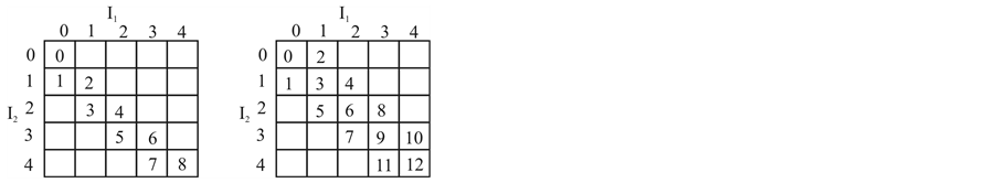
Figure 2. (a) Two diagonal (D = 2) and (b) three diagonal (D = 3) index assignment. An integer along the diagonal is mapped to row and column indices I1 and I2.
unnecessary coding overhead. Since, all the bitstreams are of different length and their embedded nature (bits in the beginning of the bitstream are more important than at the end), CRC is generated and appended for the first l bits (l = 128 bits in this paper) in each bitstream. CRC check eliminates erroneous wavelet trees from consideration which may have significant impact on the PSNR of the reconstructed image.
Arithmetic encoder [18] than maps each of the K bitstreams independently into binary strings ,
,  for description
 . Arithmetic encoder has input symbol set consisting of three symbols, namely, 0, 1, and End of Block (EoB). EoB symbol is put at the end of
  to mark the end of each variable length bitstream. Since, SPIHT is an efficient compression algorithm, further compression of SPIHT coded bitstreams by arithmetic code gives little compression gain. The main objective of arithmetic coding is to provide robustness against noise, as will be discussed in Section 3.
2.4. ERECST and Packet Formation
In the earlier section, K arithmetic coded bitstreams of variable length are generated for each description. If these variable length blocks (VLB) are transmitted consecutively, the resulting system is highly sensitive to bit errors. One approach has been to append synchronization code words to provide resynchronization at the cost of extra added bits. Otherwise, presence of a single error in the arithmetic code may cause catastrophic decoding error. Another approach for error robust transmission of variable length codes is the method of EREC [13] , which converts K VLBs into K fixed length slots (FLS). EREC has been applied in [12] for reorganizing variable length blocks of SPIHT coded bitstream before transmission over bit flipping channel.
Decoding EREC in iterative source-channel receiver is challenging because to detect the end of each VLB in the FLS, the VLB subdecoder (i.e. SISO arithmetic decoder in our case) must be embedded into the EREC decoder and decision of end of block be made based on some hard decision. Since, at the receiver EREC decoder lies in the iterative loop between source and channel decoder, finding end of block based on soft decision is difficult. This can be solved by applying ERECST proposed in [15] to the problem. ERECST isolates pure EREC subdecoder from the effects of VLB subdecoder by coding VLB lengths as side information (SI). Let L be the total number of bits in K VLBs in a description and si is the length of i th FLS, where,
 (1)
(1)
The encoding process consists of K stages. Each stage consists of filling up of FLS and coding of VLB lengths by emission of state and tail bits. Figure 3 shows the sequence of steps to convert four VLBs to four FLSs. At stage 0 (Figure 3(a)), as many bits as possible are placed into corresponding FLS. At stage n, i-th VLB, (VLB(i) has bi remaining bits) searches m-th FLS (sm slots left in FLS(m)), where  and
and  is a predefined integer sequence of length K. If both VLB(i) has bits remaining and FLS(m) has blank slots, as many remaining bits of VLB(i) as possible are placed in FLS(m). At each stage, one state bit S is emitted.
  if
if , else
  and
and  tail bits are output to code
  in binary. Let
 . Remaining bits and slots are recalculated as
  and
and . In Figure 3(b), after stage 0, only FLS(1) has bits left to be placed and searches FLS(2). Two bits are placed in FLS(2). Since, no other VLB contains unplaced bits, the process moves to next stage. In stage 2, VLB(1) places remaining three bits in FLS(3), as shown in Figure 3(d). The FLS are formed into packets and transmitted over network. Table 1 shows the SI (state and

Figure 3. Figure shows four variable length blocks VLB(0), VLB(1), VLB(2) and VLB(3) being rearranged into fixed length slots FLS(0-3) with EREC/ERECST algorithm.
Table 1. State and tail bits after different stages in
tail bits) generated for this example. The SI bits associated with a FLS are taken as a whole (SVLB) and EREC is applied to reorganize all SVLB into fixed length slots called SFLS. If b is the average VLB length, it was proved in [15] that total fraction of SI bits is less than , which in this research is 0.027. Thus we can safely assume that SI bits are transmitted with higher error protection with little coding overhead and received error free.
SFLS is utilized at the receiver side to recover variable length bitstreams back from FLS. This is done in two stages, consisting of subroutines SVLB reconstructor and VLB reconstructor. Refer to [15] for detailed algorithms for these two functions. SVLB reconstructor outputs data structure sseg , where s is the number of blank bits after the current segment of FLS(m), and next points to the next segment of FLS(m). If no more sseg is associated with current FLS, a null is put in next field. Figure 4(a) shows sseg for the four FLS formed in Figure 3. Zero in s field of sseg 0 indicates that no slots are left blank in FLS(0) after the current segment. For sseg 1, s = −1 indicates that current VLB fills up FLS(1) completely with some bits are remaining to be placed in other FLS. FLS(2) contains data segment from two different VLBs as shown by two sseg. After first segment, two bit positions are left vacant and next in sseg 2 points to next sseg. In the similar way sseg information is generated for FLS(3).
With the aid of sseg information, VLB reconstructor algorithm rearranges bits in FLS to original variable length bitstreams. VLB reconstructor creates a data structure called bseg  associated with each VLB(i), where s and
  is the number of blank bits in FLS(m) before and after current segment of VLB(i). Figure 4(b) shows the content of bseg structure for the given example. At the beginning it is assumed that all the VLBs at the receiver are empty and are waiting to get bits from the FLS. VLB(0) is reconstructed with the aid of information in bseg 0, where bits are obtained from m = 0-th FLS. Number of bits left in FLS(0) is four (s = 4) before recovering the VLB segment. Since, after current segment number of bits left is zero
 , all the bits of the FLS(0) is taken up to form VLB(0). VLB(0) gets not more bits from any FLS because next field in bseg 0 is null. VLB(1) obtains four bits from FLS(1), two bits from FLS(2) and three bits from FLS(3) as indicated by bseg 1 in Figure 4(b). Similarly, VLB(2) and VLB(3) is reconstructed. One distinctive feature of VLB reconstructor algorithm [15] is that can be observed from this example is that underlying variable length code

Figure 4. (a) Four sseg linked list generated by SVLB Reconstructor subroutine in the process of ERECST decoding of FLS created in Figure 3. (b) Four bseg linked list generated by function VLB Reconstructor, where bseg i corresponds to VLB(i).
(i.e. VLB) need not be decoded to recover VLBs back from FLS as was required with EREC in [13] .
2.5. Channel Coding and Transmission
Wireless access points (WAP) constitute the last-hop delivery link to the end user. Those packets which are not dropped in the network reach the WAP. These packets are encoded with eight state rate ½ RSCC and transmitted over wireless channel. The end user is able to able to receive packets from one or more WAPs. We assume that reception is done through two different chains of antenna and receivers (as the number of descriptions) and combined at last stage.
3. Decoding of Received Descriptions
It is assumed that the two descriptions are received through two orthogonal wireless channels. The channels are orthogonal in the sense that they are received by a single antenna by time division multiplexing or through two different antenna pairs by frequency multiplexing. Subsequent stages of decoding are explained next.
3.1. Iterative Source-Channel Decoding
In this research, channel code (RSCC) and source code (arithmetic code) are decoded iteratively. Iterative decoding allows source codec to be more robust to residual channel errors. Also, channel decoder can utilize any residual redundancy of arithmetic code in the process of decoding. We assume that input signal at the BCJR decoder  is obtained as
 (2)
(2)
where,  is Gaussian distributed random noise with variance
  and
and  is the transmitted symbol. BCJR algorithm [19] accepts channel LLR values,
  for decoding RSCC as shown in Figure 5. In contrast to Viterbi decoder which outputs hard decision, the output of BCJR decoder is soft LLR value. Let Γe be the extrinsic LLR calculated by subtracting a priori input from the output of BCJR decoder. The extrinsic information Γe is in the form of packets and if the packet has been lost (did not arrive at the receiver), its LLR value is assumed to be zero. The FLS (formed from Γe) need to be converted to VLB for arithmetic decoding. The main challenge, as discussed in earlier section, is to rearrange (EREC decode) soft information FLSs to array of (LLR values of arithmetic coded) VLB blocks
 , where k-th VLB block
  is an array of LLR values of arithmetic code. Converting fixed length slots (FLS) formed from soft information into VLB using conventional EREC is not possible in the absence of any side information. Hard thresholding of soft FLS

Figure 5. Detailed exposition of iterative source-channel decoder block in Figure 1. Dotted section outputs FLS when last of the packets for a description is received.
values to decode EREC is not useful since decoded bits are unreliable during initial iterations. Hence, we achieve this with ERECST algorithm described in Section 2.4, aided by side information sseg.
Each VLB  is now decoded by Chase-like SISO arithmetic decoder proposed by Zaibi et al. [14] . In a Chase-like decoder, hard decision on each VLB is made to obtain a binary array
 . Let
. Let  be the length of the array
 . Z is perturbed by a set of test patterns
 , which is a binary sequence that contains 1s in the location with minimum magnitude in
 . By adding this test pattern modulo-2, a new binary sequence is obtained.
 (3)
(3)
where  and vector
 . By using q number of test patterns (q = 16 in this article), the perturbed binary sequence
  may fall within the decoding sphere of valid arithmetic code. Arithmetic code is considered valid if, after decoding, a EoB symbol is detected at the end and number of decoded symbols is correct. For a valid sequence
 , following metric is calculated:
 (4)
(4)
where,  is the bipolar form of
 ,
,  and
and  calculates Euclidean distance.
  is the probability of source sequence
  obtained after decoding
 . Finally, the decoded bitstream
  corresponds to the sequence
  having the lowest metric
  among the valid sequences. Let
  be the set of positions of bits which remain unchanged among the valid sequences. These bits positions are most reliable bit positions in terms of LLR magnitude and are assigned a constant extrinsic information,
 ,
,  and
and , otherwise. The value of β was set to 4 in this research following [14] .
Thus, after a iteration Chase-like arithmetic decoder outputs VLBs of extrinsic LLR where
where . The Λe is again reorganized into fixed length blocks using EREC and applied as a priori information Γa to the BCJR decoder. After certain fixed number of iterations, let
  is obtained as the output of the arithmetic decoder.
3.2. Decoding of Multiple Descriptions
The K variable length bitstreams in  are checked for CRC, and in case of check failure, corrosponding wavelet tree is marked lost and is not utilized for further reconstruction. After SPIHT decoding of the same wavelet tree order bitstreams of two descriptions, wavelet coefficients obtained are
  and
and . If the same wavelet tree order bitstreams of descriptions (corresponding to row and column index) arrive at the receiver without being lost, decoding is performed by simple matrix lookup to get the central quantization index. However, if some of the wavelet trees of either description are corrupted or lost, central decoding can not be performed correctly by matrix lookup. In such cases, only available bitstream from either description is used to perform inverse index assignment using single channel inverse quantizer. Thus, at the receiver, a wavelet tree can be declared lost in three scenarios.
• A packet is lost in packet loss channel and all the VLB associated with it are declared lost.
• No valid arithmetic code is found in the source-channel decoder stage.
• Bitstream after arithmetic decoding, which are in fact SPIHT coded VLB, fails in CRC.
When both descriptions of same wavelet tree are lost, Song et al. [12] proposed error concealment in wavelet domain. This error concealment is based on the fact that wavelet coefficients in the lowest frequency subband have similar spatial correlation with the original image. Similar to the scheme proposed in [12] , one wavelet tree in SPIHT has four coefficients in the lowest frequency subband. If a tree is lost, these four coefficients are also lost and error concealment process replaces these four coefficients with average of its neighbour coefficients whose block have been recovered by central or side inverse quantizer. All the high frequency coefficients of the lost tree are set to zero.
4. Simulation Results
We use 512 × 512 grey-scale Lena test image for evaluating the performance of proposed algorithm under following channel conditions: 1) AWGN channel with no packet loss, and 2) combined packet loss and AWGN channel. The given image is hierarchically decomposed by 4-scale discrete wavelet transform, and then each of the subband coefficients is quantized with uniform scalar quantizer of stepsize Δ. For MDSQ, we consider two types of index assignments, with number of diagonals D = 2 and D = 3, to form two descriptions. For each description, 256 wavelet trees are constructed and SPIHT coded to generate 256 bitstreams. The stepsize Δ was adjusted to obtain coding rate of 0.5 bpp/description after SPIHT coding. 4-bit CRC was generated using generator polynomial  for the first 128 bits of a bitstream and appended to it. This results in mere 0.004 bps overhead in each description and will be compensated by arithmetic coding in next stage. All the bitstreams are independently arithmetic coded for further compression, formed into FLS using ERECST. Our scheme is more compression efficient as there is no arithmetic coding stage in the scheme proposed in [12] . Data packets were formed by packing eight slots and transmitted over packet network. Packets arriving at the WAP are encoded with 8-state RSCC with generator polynomial
 .
.
We first consider transmission over AWGN channel without any packet drop. We compare the performance of the proposed system to the baseline scheme of Song et al. [12] with 256 bitstreams per description under similar channel conditions. Figure 6 and Figure 7 shows the performance of the proposed system for 3 diagonal and 2 diagonal index assignments, respectively. For hard decision decoding of arithmetic code aided by ERECST (without iterative decoding), we can observe 1.5 dB improvement in average PSNR at Eb/N0 of 3.5 dB compared to baseline scheme, in both 3 diagonal and 2 diagonal case. With iterative decoding remarkable improvement is observed in PSNR performance. After 1 iteration of soft decoding of arithmetic code, there is a

Figure 6. Performance comparison of proposed scheme for transmission over AWGN channel (with no packet loss) for 3 diagonal index assignment case (D = 3).
maximum gain in PSNR of 3 dB at Eb/N0 of 3.5 dB in 3 diagonal case. The improvement is 3.5 dB compared to baseline scheme for 2 diagonal case. The maximum improvement after 4 iterations is observed at relatively noisy region of Eb/N0 = 3 dB. The gain in PSNR is 6 dB and 7 dB respectively for 3 and 2 diagonal cases, compared to baseline system under AWGN channel. Improvement in PSNR saturates after 4 iterations. The results are obtained by averaging 100 trials for each channel condition. In Figure 8, we give examples of reconstructed images in order to illustrate the improvement in visual quality. Figure 8(a) shows improvement in image quality compared to baseline scheme (Figure 8(b)) at Eb/N0 of 3 dB. These results have demonstrated that the proposed improvement in MDC scheme makes it significantly noise robust compared to existing schemes in literature.
Second set of simulations were carried out to demonstrate the performance of our proposed scheme over channels with both packet loss and random noise. The objective is to evaluate the degradation of PSNR value for different number of packet lost. We conduct experiments with the proposed system only as its superiority compared to baseline system has been demonstrated in the earlier set of simulations. The results for different wireless channel conditions are shown in Figure 9 for D = 3 and Figure 10 for D = 2. We obtain the results after averaging 200 trials of transmission over each channel condition. It is evident from the figures that proposed scheme is able to achieve graceful degradation of image quality as more and more packets are lost in packet network. The degradation is more evident in high Eb/N0 region (>3 dB) whereas, there is smaller effect of packet

Figure 7. Performance of proposed scheme for transmission over AWGN channel (with no packet loss) for D = 2.
 (a) (b)
Figure 8. Image recovered by proposed scheme (a) compared with recovery by baseline system (b) at Eb/N0 of 3 dB and D = 3. PSNR of images (a) and (b) are 33.6 dB and 27 dB, respectively.

Figure 9. Performance of proposed scheme (D = 3) for transmission over packet loss channel at different values of Eb/N0 for wireless channel.

Figure 10. Performance of proposed scheme (D = 2) for transmission over packet loss channel at different values of Eb/N0.
loss in low Eb/N0 region. These results demonstrate excellent capability of the presented system to combat packet loss and noisy channel via integrated design.
5. Conclusion
In this paper, we proposed a multiple description image transmission scheme over hybrid channel consisting of combined packet loss channel and AWGN channel. It was shown that robustness to packet loss and channel noise can be improved by utilizing the soft channel information at the receiver. We achieved this by iterative decoding between Chase-like SISO arithmetic decoder and BCJR decoder, with ERECST stage in-between. Significant gain in PSNR is obtained over existing scheme with lesser number of bits transmitted.