1. Introduction
The problem of continuous production of energy sufficient for feeding the modern microsystems with an almost unlimited service life such as remote sensors should be related to searching for power sources in the environment.
Such kinds of energy as radio frequency energy, energy of heat, energy of sound, solar energy and wind energy have either low power or are not constantly available. To power remote microdevices with the power demand on the order of several milliwatts to microwatts it is most promising to use the energy of the solid material microvibrations, because these microvibrations are constantly present and are sufficiently strong [1].
There are numerous recent publications that describe the development of microgenerators of electrical energy, including MEMS generators capable of converting mechanical energy from the ambient medium to electrical energy, so called “energy harvesters” [2-5]. Electrostatics is the most promising physical principle for electrical energy microgenerators, because electromagnetic generators of energy are ineffective in the range of low-amplitude vibrations and small sizes of the transdusers [6] while piezoelectrical generators are ineffective at low frequencies of vibrations [2,3].
The operation of electrostatic generator is based on the work of mechanical forces transferring an electrical charge against electrostatic forces of attraction of unlike charges [7]. Depending on the method of induction and transportation of this charge, the generators can be divided into two classes. In the first class, the charge produced by some external action, for instance, by an electric arc or friction, is transferred by a transporter: a belt (Van de Graaf generators) [7] or a disk (friction machines). In the second class, the charged plate of the capacitor moves. Depending on the presence or absence of a built-in charge in this capacitor, such devices are divided as either electret [8] or capacitance generators, e.g., Toepler or Felichi machines [7].
For electrostatic capacitance generator (Figure 1(a)), the separation of the plates (vertical or lateral) of the capacitor С(t) initially charged from the voltage source V0 up to the value Q0 = CmaxV0 (where Cmax is initial maximal value of capacitance) in the conditions of open circuit results in grows of voltage on the capacitor up to the value
 , (1)
, (1)
here Vmin = V0, and, respectively, of the energy of capacitor from  to
to
 , (2)
, (2)
where  is capacitance modulation depth.
The produced electric energy  is transferred to load R. After that, the capacitor plates return to the initial position and are charged by the voltage source, and the energy conversion process is repeated. The power developed by such a generator is
  (where f is the repetition frequency of conversion cycles).
Such capacitor microgenerators having both in-plane and out-of-plane design were intensively investigated earlier [9-18]. Note that capacitance microphone is a particular case of these generators [19]. Relatively low value of C(t) is the main drawback of these generators, but it is removed in micro design with small gaps between the plates of capacitor. Another defect is the need to use switches both for electric energy pick-up onto the load resistance R and for recharging the capacitance C(t) in the cycle of energy conversion (see Figure 1(a)).
In electret generators (see, e.g. [8,20-25]) (Figure 1(b)), the condenser of generator is charged owing to a built-in charge, so the use of switches for recharging is not necessary. It was shown in [26] that the optimal power of this generator:
 , (3)
, (3)
where CF is dielectric capacitance, QP is polarization value,  is mean value of the structure capacitance. The power of electret generator may be increased by a factor of η2 which is just the same method of load switching as described above for capacitance generator (see Figure 1(a)), where V0 = 0. However the need to use a dielectric with relatively low value of ε results in the necessity of the work of device in the range of high voltages to reach the required power density.
A more feasible version of using the capacitive method of electromechanical conversion was described in [27,28], and its circuit is shown in Figure 1(c). The mechanical force is converted to electric energy by changes in the capacitances of each of the two capacitors Ci(t), i = 1, 2, in time. They are initially charged to a potential V0 and are mechanically coupled in such a way that the capacitors always have opposite phases (a maximum of C1 corresponds to a minimum of C2, and vice versa). In this case, it is not necessary to use the switch as in the case of one-capacitor generator. The electric energy is released on the load resistance R as a result of flowing of alternating current I(t) through this resistance. If the generator has an initial charge Q0 = (C1 + C2)V0 distributed between the capacities C1 and C2, then the system can operate for an unlimited period of time in the idealized case, without charge leakages, periodically transferring some part of the charge from one capacitor to the other and back.
The present work is aimed at performing modeling and simulations and also the experimental modeling for various types of two-capacitor electrostatic generators of energy with no necessity to connect a source of electric energy in each cycle of energy conversion for compensating charge losses induced by leakage currents in generating elements.
2. Classification of an Energy-Independent Two-Capacitor Generators
Various versions of implementation of two-capacitor

Figure 1. Various circuits of capacitance electrostatic generators: (a) Capacitance machine or electret voltage generator (at V0 = 0); (b) Electret current generator; (c) Ideal two-capacitor generator; (d) Two-capacitor generator with loss compensation by a current source; (e) Two-capacitor generator with loss compensation by a voltage source; V0 is the voltage source, I0 is the current source, R is the load resistance, and r is the leakage resistance.
generators are based on the ideal generator circuit shown in Figure 1(c). They differ both in design principle based on in-plane vibrations of moving electrode (when the element area is modulated) or out-of-plane ones (for which the interelectrode gap is modulated) and in the method of compensation of charge losses caused by leakage currents in the generator capacitors.
Such compensation can be provided by an external source of electric energy. One can use a current source, i.e., a source that supplies constant current and has a sufficiently high (in the ideal case, infinite) internal resistance, which is connected to one of the generator capacitors (see Figure 1(d)). Alternatively, the voltage source (whose internal resistance is low) could be used. In the latter case it is necessary to use a switch connecting the source to one of the capacitors for a time sufficient for capacitor recharging (Figure 1(e)).
Moreover, charge losses can be compensated by using an additional low-power generator connected to the input of the basic generator and consuming a minor portion of mechanical energy of the system, for instance, by using the electret effect.
It is also possible to compensate charge losses by organizing a feedback for transferring some part of energy from the generator output to its input [13].
Note that because the fixed electrode of capacitor can be insulated by deposition of ferroelectric (dielectric) with high values of dielectric constant ε and breakdown field strength the specific capacitance and power capacity of the structure at small gaps will be high enough.
It should be noted also that out-of-plane construction has higher power density compared with in-plane one because of the least value of interelectrode gap, which could be reached for this configuration. These gaps are not attainable for out-of-plane design because it is necessary to keep electrodes in plane parallel state during the operation at high enough areas of them.
3. Analysis of Possible Versions of Implementation of Two-Capacitor Generator Circuits
3.1. Compensation of Charge Losses with the Use of a Current Source
The circuit based on this principle is shown in Figure 1(d). Operation of this generator is described by the system of differential Equations
 (4)
(4)
V1(t) and V2(t) are the voltage drops on capacitors C1 and C2, respectively; σ1(t) and σ2(t) are the conductivities arising owing to leakages in these capacitors (in the general case, they are time-dependent).
Two operation modes of two-capacitor generators are possible: with lateral in-plane shift of the plates (with variations of the electrode overlapping area, a particular case is the rotor-type generator) and with vertical out-of plane vibrations of the plates (with variations of the interelectrode gap). To obtain the maximum efficiency of energy generation, the motion of the capacitor plates in the opposite phases is provided in both cases.
3.1.1. Two-Capacitor Generator with Lateral Shift of the Capacitor Plate
In the case with capacitances change in the opposite phases and with lateral shift of the capacitors plates, their total capacitance is constant:
 (5)
(5)
In a particular case, when the charge leakage is proportional to the electrode overlapping area, we have
 (6)
(6)
In the case of constant leakages:
 , (7)
, (7)
and for both cases
 (8)
(8)
System (4) was solved numerically in [28], and it was shown that the solution is determined only by two dimensionless parameters characterizing the load properties of the system (fRC0) and the charge losses due to leakage currents . The numerical simulation made in [28] was aimed mainly to the analysis of power generation efficiency for in-plane mode and no analytical estimates of generated power were done.
Let us estimate the value of the maximum energy generated by this generator during one conversion cycle and, correspondingly, the power. As the first approximation, we consider the ideal two-capacitor generator (see Figure 1(c)), in which the capacitors are initially charged to the potential V0, and the charge losses are negligible. Taking into account Equation (5), we obtain
 (9)
(9)
where Q0 = QΣ(0) is the total initial charge accumulated on the capacitors. As there are no charge leakages in this case, the charge is retained during the entire time of generator operation.
Under the conditions described above, there is an initial segment of current relaxation with the characteristic time constant of the order of RC0; during this time a dynamically equilibrium mode of generation is established owing to charge redistribution on the capacitors. Note that initial behavior of voltages Vi depends on initial phase of capacitances alteration and the initial conditions of setting the amplitude and frequency of their oscillations. We do not analyze this case in detail here, because the same dynamically equilibrium state is established for all initial conditions.
Taking into account Equations (1), (5) and (9) and also that Q0 = CminVmax + CmaxVmin, it is easy to get:
 , (10)
As both capacitors participate here in energy conversion, we can easily show that the energy W2 produced during one conversion cycle is
 , (11)
 (12)
(12)
is initial energy accumulated in the capacitors and P is the power of the two-capacitor generator and P0 = W0f. A comparison with one-capasitor generator (Figure 1(a), energy W1) results in the following expression
 (13)
(13)
For , we have
 (14)
(14)
Here the power of the two-capacitor generator (with identical initial voltages) is lower because of the nonoptimum incomplete charging of the capacitors Ci under the initial conditions mentioned above.
The numerical solutions for in-plane mode of ideal generator are shown in Figure 2, where the dependence of P/P0 on fRC0, where P0 = fW0, is presented.
The dependence of the maximum power Pmax/P0 on the modulation factor η (Figure 3, curve 1) for the ideal generator is almost linear in the interval  and is adequately described by (11) and curve 3 in Figure 3. At small values of η, 1 < η < 3, there are significant deviations from Equation (11), because Vmax/Vmin < η in this case and Equation (1) is invalid.
With our method of normalization used here the curves in Figure 2 depend only on the capacitance modulation factor. The curves in Figure 3 are independent on the absolute parameters of the model, i.e., they have a universal character and describe all possible solutions of system (4) for the ideal generator case. From this viewpoint, we called them the “characteristic” curves.
An example of the numerical solution of (4) illustrating the operation of the two-capacitor generator in the

Figure 2. Characteristic curves of the generated power for the ideal generator: η = 2 (1), 10 (2), and 100 (3).

Figure 3. Characteristic curves of the maximum generated power Pmax/P0 versus the capacitance modulation factor for the following operation modes: ideal generator with lateral shift of the plates (1), lateral shift of the plates with modulation of charge leakages synchronized with capacitance modulation (2), lateral shift of the plates with constant leakages (4), out-of-plane antiphase vibrations of the plates (vibration generator) (5), lateral shift of the plates with recharging the capacitor C1 from a voltage source under conditions C1(0) = Cmax (6), out-of-plane antiphase vibrations of the plates for the ideal generator at C1(0) = Cmax (7) and at C1(0) = C2(0) (8), and analytical estimate for the ideal generator from Equation (13)—curve (3).
absence of charge losses and with a set of parameters corresponding to its peak power is shown in Figure 4.
A typical feature of two-capacitor generators is the optimum of the normalized power P/P0 in the frequency range f ~ 1/RC0, which is consistent with the results of the numerical analysis (see Figure 3), because at high frequencies the capacitors Ci do not have enough time to exchange the charge during one cycle of energy conversion, whereas at low frequencies the charge passes to the

Figure 4. Time evolution of the capacitance (1), voltage (2), and charge (3) for one of the generator capacitors at the vicinity of optimum power (η = 10 and fRC0 = 1.9).
second capacitor faster than the capacitance of the generating capacitor reaches the minimum value. As the capacitance modulation factor η increases, the generator power P/P0 also increases, and its peak is shifted toward higher frequencies.
Let us consider the operation of the two-capacitor generator taking into account the charge losses due to leakage currents and its compensation from an external current source. In the equivalent circuit shown in Figure 1(d), the charge losses are shown as conductivities σi(t) connected in parallel to the capacitors Ci(t). A d. c. current source I0 is used for compensation of these losses. The operation of such a generator is described by the system of differential Equations (4) with initial conditions corresponding to the steady state of the system with the current I0 flowing in the circuit.
We analyze first the case with capacitance and conductivity modulation in accordance with an identical sinusoidal law, i.e., when the conditions (5) and (6) are satisfied, i.e. when the leakages are proportional to the area of overlapping of the capacitors plates. Subtracting the corresponding components of the third Equation of system (4) from the left and right sides of the second Equation of the same system and taking into account Equations ((5), (6), (8)) we obtain the expression for total charge:
 (15)
(15)
Using the initial condition that describes the charge of the capacitors from the current source I0 in the steady state: QΣ(0) = I0C0/σ0 we can easily show that Equation (15) has only one solution (Figure 5, curve 1)
 (16)
(16)
Then, all estimates of the maximum energy produced

Figure 5. Time evolution of the total charge of the generator capacitances at fRC0 = 9.6 and η = 10: modulation of leakages synchronized with modulation of the capacitance, Equation (18)—curve (1), and constant leakages (2) (frC0 = 9.6 × 10²). The inset shows a zoomed-in fragment of curve 2.
by the ideal generator during the period of energy conversion and the estimates of the generator power are valid at a certain effective value of the initial voltage
 (17)
(17)
So the characteristic curve 2 of Pmax/P0 as a function of η completely coincides with curve 1 for the ideal generator, see Figure 3.
The second case also observed in practice is the case with constant leakages (see [28]). A significant difference of this solution from the case of negligibly small leakage currents or proportionality of the conductivity σi to the electrode overlapping area considered above is the initial decrease in the total charge QΣ in time with the time constant of rC0/2. This effect is explained by small oscillations of leakage currents during the vibration period leading to a certain progressive decrease in the charges Qi and QΣ. Note that in most realistic cases, however, the decrease in the total charge  is not more than a factor of 2.
Thus, a typical feature of the two-capacitor generator with constant charge leakages is an additional decrease in the generated voltage by a factor of k and, correspondingly an additional decrease in power by a factor of k2, as compared with the above-described case when the leakages are proportional to the electrode overlapping area (6). The dependence of the power P/P0 on fRC0 is qualitatively similar to the corresponding curves for the ideal generator with the only difference that it is additionally affected by the leakage currents (parameter frC0): it increases linearly with decreasing leakages at a constant current I0. In our scales, the value of P/P0 is almost independent of frC0 if the leakages are sufficiently small: . Other dependences, such as Pmax/P0(η), see Figure 3, curve 4, and Pmax/P0(fRC0) are qualitatively similar to the corresponding characteristics of the ideal generator.
Note that the quasi-steady mode of the generator operation is not reached under real conditions (e.g., in the regime of harvesting the energy of microvibrations of environment), when the modulation frequencies and the amplitude of modulation change in a shorter time than time constant of power decay ; therefore, the maximum of the generated power lies between curves 1 and 4 in Figure 3.
3.1.2. Two Capacitor Generator in Vibration Out-of-Plane Mode
If the two-capacitor generator works at the interelectrode gap modulation mode, when the electrode overlapping area remains constant, then the condition of the constant total capacitance of the capacitors in time (5) is not fulfilled. In this case, the gaps of two capacitors are modulated in antiphase in accordance with a sinusoidal law, while the capacitance of each capacitor is inversely proportional to the gap value (Figure 6, curves 1 and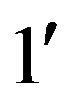 ; the quantity
  has the meaning of a capacitance averaged over the period of vibrations). Therefore, the capacitance of each capacitor is close to the minimum value during the major part of the period of vibrations T. The greater the capacitance modulation factor η, the more pronounced this effect: when the plates of one capacitor become separated (curve 1, motion toward decreasing C1(t)) and the voltage on this capacitor increases accordingly (curve 2), the charge from this capacitor flows to the second capacitor whose capacitance C2(t) is still low (curve
 ). Thus, in contrast to the lateral shift of the plates, the charge overflow is not matched with the alteration of the second capacitor: the peak of V1(t) occurs earlier than the peak of C2(t), i.e., the charge from the first capacitor flows to the second capacitor mainly

Figure 6. Time evolution of the capacitances of the first (1) and second ( ) capacitors and the voltage (2) for the first capacitor of the generator in the optimum power region. Mode of out-of-plane antiphase vibrations, η = 10, and fRC0 = 0.854.
during the time when its capacitance is close to the minimum value.
The absence of “synchronization” of the charge exchange between the capacitors in the generator in the out-of-plane mode reduces the generator power (see Figure 3, curve 5, P0 is determined by Equation (12), in which C0 is replaced by ), which is manifested as a decrease in the ratio
  (see Figure 6, curve 2).
It should be noted that for the ideal generator in out-of-plane mode the generated power is strongly dependent to the initial phase of the gap (capacitance) variation (see Figure 3, curves 7, 8 and 1), because of the strong difference of the initial charge. In this case, the ultimate power for two capacitor generators could be reached, because it is possible to ensure the minimum possible gaps between the electrodes of the generator capacitors due to the presence of high dielectric constant sub layer mentioned above and, therefore, the maximum possible values of the capacitance.
3.2. Compensation of Charge Losses with the Use of a Voltage Source
The charge losses can be compensated with the use of a voltage source by connecting the source for a short time to one of the capacitors (see Figure 1(e)). The charge losses on the second capacitor are compensated owing to the current flowing through the load resistance. Breaux [27] considered another method: the charging of both capacitors. In this case, however, highly accurate synchronization of two switches is needed because even a small delay in commutation of switches leads to significant reduction of the generation efficiency.
The recharging voltage pulse should be applied at V1(t) < V0 and it should be finished at C1(t) = Cmax. Note that both for in-plane and for out-of-plane vibration mode this way of recharging results in pronounced growth of the captured charge and therefore the generated power. This growth compared to ideal generator is by a factor of 4 for in-plane mode and it is more pronounced for the case of out-of-plane vibrations, because of high values of Cmax, which can be reached in this case. In this mode the power approaches to its limiting value characteristic to the case of ideal generator with maximum captured charge (cf. curves 5 and 6 in Figure 3) and maximum possible power. An example of the optimum synchronization of the switch connecting the source V0 in agreement with the capacitance modulation periods for the case of outof-plane antiphase shift of the moving electrodes of the capacitors is shown in Figure 7.
4. Experimental
To demonstrate the possibility of electric energy generation at the action of mechanical forces we performed

Figure 7. Example of solving the problem of compensation of charge losses by recharging the capacitor from a voltage source taking into account the leakage currents. Mode of out-of-plane vibrations of the capacitor plate: total charge. Recharging pulse duration 10 μs, amplitude 10 V, supply period 40 ms, number of cycles per the period N = 10, frequency 1000 Hz, Cmin = 800 pF, η = 10, R = 2 × 10⁶ Ω, and r = 5 × 10⁸ Ω.
experimental studies of the model of two-capacitor generator with rotational movement of common plate placed between two stator plates. Each plate was divided into 12 sectors by such a way to provide with the central plate two series connected capacitors modulated in antiphase when central plate is rotating. The area of the electrodes was 25 cm2. The moving electrode was fixed on the shaft of a d. c. motor, the resulting capacitor modulation frequency was 120 - 600 Hz. The gap between the plates was 100 - 200 μm, the capacitance C0 had the order of 250 - 350 pF, and the modulation depth was η = 1.8 - 3.5; these parameters were determined by independent measurements. The current through the load resistance I(t) and the voltage on it V(t) were measured by a digital oscilloscope using coupling amplifier.
The oscillogram characterizing the efficiency of energy generation is shown in Figure 8. A charge of 2 × 10⁻⁸ C was preliminary injected at the time t = 0 into this structure by a short pulse of voltage of 80 V. After that, this charge determined a flow of the current up to 8 μA (acting value) through the load resistance R = 10 MΩ in the process of rotation of the moving electrode with the frequency of capacitance modulation of 400 Hz. The initial time of voltage redistribution is of order RC0 = 3 × 10⁻³ s, in the case under consideration this time is less than the period of capacitance alteration and it is practically unvisible. After that dynamically equilibrium mode of generation is established. Therefore, the measured initial amplitude of the voltage on the load resistance R (e.g., 40 V, based on the data in Figure 8) was used to calculate the power of the ideal generator in this mode on the basis of the proposed experimental model. Initial

Figure 8. Relaxation of voltage oscillations in the load resistance of the two-capacitor generator mockup (C0 = 300 pF, η = 1.8, R = 10 MΩ, and f = 400 Hz).
charging of the capacitors ensures energy generation for a long time (up to 1000 s). During this time, more than 4 × 10⁵ cycles of energy conversion with the use of this charge take place, and the Joule energy released on the load resistance is much greater than the energy spent on initial charging of the generator capacitors, more than 104 times in the example on Figure 8. Based on the time constant of charge decay, we can easily estimate the leakage resistance; for the circuit considered, it is approximately 1012 Ω. The power developed by the generator with a 80-V starting voltage was 1 mW.
It was experimentally found that the maximum voltage formed by this generator reaches 400 - 500 V, it is limited by air gap breakdown; therefore, the power reaches 25 mW (the specific power can reach 1 mW/cm2).
To confirm the main consequence of the generator model developed, i.e., the universal character of the dependences of the generated power on the load resistance R, we studied the specific features of energy generation at the initial stage of the process until the effect of the leakage currents was manifested (in this period, as have been shown above, the current amplitude is close to its value for the ideal generator).
The loading curves plotted in the RfC0 − P/P0 coordinates for different modulation frequencies of the generator capacities were found to be almost coincident, i.e., to have a universal character and also to agree well with the model described above (Figure 9).
5. Discussion and Conclusions
The analysis of all the modes of operation of a two-capacitor generator based on overflow of the charge accumulated in the capacitors through the load resistance connected between two capacitors whose capacitances are modulated in the opposite phases owing to application
Figure 9. Characteristic loading curves of the two-capacitor generator with compensation of losses from a voltage source: f = 400 Hz (1), f = 100 Hz (C0 = 300 pF and η = 1.8) (2), and calculation by the proposed model (3).
of a mechanical force to moving electrodes demonstrated the high efficiency of this generator.
In this generator, in contrast to its single-capacitor prototype there is no need in charge recuperation at each cycle of energy conversion; therefore, it ensures a high efficiency of energy conversion limited only by small leakage currents determined by structural features. In the idealized case, without charge leakage channels, the generator can operate for an infinitely long time, generating electric energy under the mechanical action.
The charge leakage channels are always exist; therefore, for the generator power to be maintained, the initial charge should be recovered either by direct injection of the charge by small portions from a current source (continuous recovery in each cycle) or from a voltage source connected for a short time to one capacitor in a certain phase of variation of its capacitance (after N cycles of energy conversion).
Numerical solutions of the problem for both cases are obtained and analytical estimates for the generated power in some limiting modes are given. In the dimensionless form, these solutions have a universal character: if the leakage resistance is much greater than the load resistance, the curves of P/P0 as a function of fRC0 have a maximum Pmax/P0 located in the vicinity of RC0 = 1/f, which is shifted toward fRC0 > 1 with increasing capacitance modulation factor η. The form of these curves depends on the value of η only; the dependence of Pmax/P0 on η has a common character for all sets of particular generator parameters.
One of the most important characteristics of the generators considered here is the magnitude of the charge participating in the energy generation process. It is demonstrated that compensation of charge losses by connecting a voltage source to one capacitor at the instant when its capacitance reaches the maximum value allows a simultaneous increase in the generator power to the maximum value exceeding the power of the ideal generator by a factor of 4.
It is shown that the power of a two-capacitor generator in out-of-plane mode based on modulation of the distance between the electrodes under conditions with no charge losses depends on the initial positions of the capacitor plates: the maximum power is obtained when the distance between the electrodes has the minimum value for one of the capacitors. In such a generator, the compensation of losses from the current source is less effective and the generated power is lower because of the absence of synchronization of charge transfer from one capacitor to the other. In the case with compensation of charge losses from the voltage source, however, the power of the out-of-plane generator drastically increases and reaches the values of Pmax/P0 approaching similar values typical for the generator with the lateral shift of the electrodes, but the absolute value of Pmax is ultimate in these conditions.
Note that the specific power of the considered device, in our opinion, will be the most possible in the inverse regime of operation of petal micromotors, described by us earlier, see, e.g. [29,30].
The universal character of the dependence of P/P0 on fRC0 allowed us to perform an experimental study of the basic characteristics of such generators even with the use of their mockups with an arbitrary capacitance modulation factor.
The study of mockups of two-capacitor rotational generators showed that the experimentally obtained and normalized dependences of P/P0 on fRC0 agree well with the proposed model.
The present study of two-capacitor generators allows us to pose a problem of creating electrostatic microgenerators capable of operating without a voltage source. Such generators fabricated with the use of the microelectronics technology are designed for power supply for microchips with long-time service life. The specific power of these generators according to our evaluations will be up to 1 - 10 mW/cm2.