Reasonable Drive Selecting of Parallel Mechanisms Based on Screw Theory ()
1. Introduction
Parallel mechanisms have been investigated during the last two decades, due to the fact that they present some advantages in a comparison with serial structures: the ability to perform fast motions, more rigidity and accuracy, and high force or torque capacity for the number of actuators as the actuators are arranged in parallel form [1]. In parallel mechanism, there may have different drive options due to the existence of many motion pairs. Hence, the drive selecting of parallel mechanisms plays an important role both in dynamics and in kinematics. The irrational drive options may lead to lower work efficiency, uncontrollable motion and structure destroyed. Therefore, a growing number of scholars pay attention to select the reasonable actuators components of multi-DOF parallel mechanisms [2] [3].
Yang [4] proposed the drive pairs were selected by rigidizing the n input joints, where the n represents the number of the DOF. Zhao [5] investigated a detecting method of input interference in a spatial parallel manipulator based on the concepts of reciprocal screws and their linear correlativity. Klein projective geometry theory was used to discuss screw system dependence in [6], and the problem of discriminating input selecting reasonability was solved.
In this paper, the 4-PPPS (prismatic-prismatic-prismatic-spherical) parallel mechanism was introduced as a research object. Based on the screw theory, the reasonable combination types of input scheme was solved by rigidizing the input joints, the mechanical workspace was drawn by the method sphere-coordinate searching [7], and the rationality of input scheme for this mechanism was identified according to the continuity of the workspace.
2. Reasonable Drive Selecting of Parallel Mechanisms
2.1. The Principle of Driver Selecting
In theory, the selection principle of the parallel mechanism should be based on the definition of the degree of freedom that “Degree of freedom [mobility] of a kinematic chain or a mechanism: Number of independent coordinates needed to define the configuration of a kinematic chain or mechanism” [8]. According to the definition, when given the input parameters, the motion of the body is uniquely determined. Based on screw theory, the principle of drive selecting of multi-DOF parallel mechanisms can be summarized as follows [9]:
When rigidizing the actuators, the constraint reciprocal screw system  of parallel mechanisms is composed of the constraint reciprocal screw generated by all branches. The
  is consisted of two parts: the
  and the
 , where the
  is the constraint screw system generated by the structure of parallel mechanisms and the
  is the constraint screw system generated when rigidizing the selected actuators.
If the rank of reciprocal screw is 6,
 (1)
(1)
The drive selecting is reasonable; otherwise re-select the driver of parallel mechanisms.
2.2. The Input Selection of 4-PPPS Parallel Mechanism
The 4-PPPS is consisted of four branched chains, each branch is identical and composed of three prismatic joints and one spherical joint, as shown in Figure 1, they are arranged in the order PPPS (prismatic-prismatic-pris- matic-spherical) where the three prismatic joints are mutually perpendicular. According the “modified G-K formula” [10] [11], the degree of the 4-PPPS parallel mechanism is 6. Therefore, 4-PPPS parallel mechanism must be chosen 6 motion pairs as its actuators. Because of huge load imposed on the prismatic joint along the axis Z and avoiding redundant drive, three prismatic joints (here are branched chains 1, 2, 3) along the axis Z in the mechanism are selected as mechanical actuators. Now just need to analysis the remaining three actuators which make the mechanism to translate along the axis X or Y.
O―XYZ is the reference coordinate system where the point O is located in the center of the rectangle ABCD, and O’―X’Y’Z’ is the moving coordinate system where the point O’ is located in the center of the platform, as shown in Figure 2. Taking out the branch i (i = 1, 2 and 3), the screw system of the branch i can be represented as:
![]()
Figure 1. The kinematic principle of 4-PPPS parallel mechanism.
![]()
Figure 2. The schematic diagram of 4-PPPS parallel mechanism.
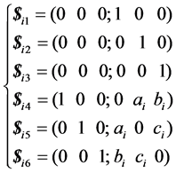 (2)
(2)
where, the letters ai, bi, ci (i = 1, 2, 3) are constant that their value are depended on the coordinate value of the points A’, B’, C’.
Analyzing the Equation (2), each screw can constitute a 6 × 6 matrix, and its rank is 6. So each branch is linearly independent and the mechanism itself has not constraint screw. According to the principle of drive selecting, rigidizing the three prismatic inputs, i.e. the screw  (i = 1, 2 and 3) is eliminated, so each branched chain generates a force screw along the Z-axis. Therefore, the three inverse screws on the platform worked by three branches are as follows:
 (3)
(3)
The rank of the coefficient matrix which is consisted of three reciprocal screws above is 3, that means only three degrees of freedom of 4-PPPS mechanism can be restricted when the three actuators’ direction along the Z-axis is locked. At this moment, the mechanism will not move along the Z-axis and rotate around the X-axis and Y-axis. The extra three moving control along the X-axis or Y-axis is in need: 2X-1Y or 2Y-1X.
For the branched chains 1, 2, 3, there are 8 prismatic joints along the X-axis or Y-axis, only need to randomly select three of them; therefore there are 18 different kinds of combinations. Considering the symmetry of the structure configuration, the same combinations will be deleted, and eight different drive selecting combinations will be obtained finally. According the principle of the actuators distributed on each basis point, the classification is shown in Table 1.
2.3. Analysis of the Rationality of Input Scheme for 4-PPPS Parallel Mechanism
The coordinate [xA yA zA]T (the value of xA, yA and zA is not 0) of the spherical joint center point A’ fixed on the branched chain 1 is deduced by the reference coordinate frame. Analyzing the combination XA-YA-XB, the constraint screw of the branched chain 1 is,
 (4)
(4)
The constraint screw generated by the branched chain 2 is,
 (5)
(5)
![]()
Table 1. The combination types of input scheme.
According the Equations (2)-(4), the constraint matrix consisted by total constraint reciprocal screw which is acted on platform by all branches is,
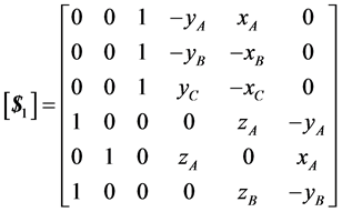 (6)
(6)
Considering the symmetry of the mechanism, the numerical relationship among the center point coordinates of spherical joints is deduced, and the rank of the constraint matrix above calculated by MATLAB is five, i.e.
Dim ( ) = 5. Therefore, the selection of the first combination is unreasonable.
In the same way, the remaining seven combinations are chosen respectively as actuator to analysis, and the seven constraint matrices consisted by total constraint reciprocal screw which is acted on platform by all branches can gain are respectively,
![]() (7)
(7)
![]() (8)
(8)
![]() (9)
(9)
![]() (10)
(10)
![]() (11)
(11)
![]() (12)
(12)
![]() (13)
(13)
The rank of the constraint matrices (5)-(6) is 5, while the rank of the constraint matrices (2)-(4) and (7)-(8) is 6, i.e. dim(![]() ) = dim(
) = dim(![]() ) = 5, dim(
) = 5, dim(![]() ) = dim(
) = dim(![]() ) = dim(
) = dim(![]() ) = dim(
) = dim(![]() ) = dim(
) = dim(![]() ) = 6. Hence, the combinations 5 and 6 are unreasonable, the combinations 2, 3, 4, 7 and 8 are reasonable. The reasonable selecting combinations are summarized in Table 2.
) = 6. Hence, the combinations 5 and 6 are unreasonable, the combinations 2, 3, 4, 7 and 8 are reasonable. The reasonable selecting combinations are summarized in Table 2.
3. The Workspace of 4-PPPS Parallel Mechanism
The combination XA-YA-XB is chosen as mechanical actuators, the initial state parameters of platform are given as follows: A’B’ = 500 mm, B’C’ = 1500 mm, AA’ = 450 mm. The range of motion of the prismatic joints installed at the four basis points along the axis XYZ is ±50 mm. The workspaces of 4-PPPS parallel mechanism is calculated by a Numerical method, i.e. give the initial position and pose, find out the set of the rotational angle for spherical joints and the translational distance for prismatic joints. Figure 3 shows a sphere- coordinate searching method. The searching parameters ![]() are given at the beginning. When
are given at the beginning. When ![]() and
and![]() , the
, the ![]() will be increased at the step
will be increased at the step![]() .
.
When any one of mechanical drivers reaches the limit position, the reference point will move to the boundary of the workspace. Set the incremental step ![]() and
and![]() , and the searching operations above are repeated until the parameters
, and the searching operations above are repeated until the parameters ![]() and
and![]() .
.
Figure 4 shows the computing result of workspace. As all prismatic joints of 4-PPPS parallel mechanism may be chosen as its actuators, each branch can be achieved to translate along the axis XYZ, which can deduce that the mechanical workspace is a regular three-dimensional graphics. At the end, the rationality of the input scheme is identified based on the condition showed on Figure 4 that the workspace is a cube and the boundary of workspace is consecutive.
![]()
Figure 3. The sphere-coordinate searching method.
![]()
Figure 4. The workspace of 4-PPPS parallel mechanism.
![]()
Table 2. The reasonable combination types of input scheme.
4. Conclusions
1) All possibilities of actuators selecting for the 4-PPPS parallel mechanism has been analyzed based on the screw theory in this paper, and the five of them are proved to be reasonable.
2) Choosing the one as mechanical actuators, the workspace of the 4-PPPS parallel mechanism is deduced according to the rational input scheme, and the rationality of input scheme for this mechanism is identified on the basis of the continuity of the workspace.