1. Introduction
Carbon nanotube, which is one of the allotrope of carbon, has been attracted worldwide after their discovery in 1991 by Iijma [1] . Carbon nanotubes have distinguishing properties like mechanical, thermal, electrical, etc. which make them useful in many fields of our daily lives.
CNTs can be classified into two main categories: single-walled carbon nanotubes (SWNTs) and multi-walled carbon nanotubes (MWNTs) [2] . It is of great interest to understand what factors control the nanotube sizes, number of shells, the helicity and the structure during synthesis; this is due to the fact that different atomic structure of the tubes may result in great changes in their properties [3] -[5] .
In general, CNTs are synthesized by arc discharge [6] , laser ablation [7] , chemical vapor deposition (CVD) [8] and spray pyrolysis [9] .
Although first two methods from above mentioned can produce high quality SWNTs, the available quantity from both arc discharge and laser ablation is limited.
CVD is more promising and cheaper method for synthesizing CNTs, for large scale production. Because good quality SWCNTs are quite expensive due to synthesis technologies. The other problem is to choose the suitable eco-friendly carbon source for synthesizing high quality CNTs with good parameters and low cost.
Therefore many authors used different carbon sources, like cyclohexane, acetonitrile [10] , benzene [11] [12] , xylene [13] , alcohols [14] et al. for synthesizing of both single and multiwall carbon nanotubes by CVD method.
In this work, we demonstrate CNTs, synthesized by using byproduct of Caspian oil refiner.
Caspian oil is one of the high quality and light oil in the world. Oil in the Caspian has a long history—indeed it is one of the earliest oil production regions in the world, with Baku a major oil center in the second half of the 19th century and beyond. This Caspian Sea oil utilize as gasoline, jet fuel, LPG, fuel oil, asphalt after refining.
We had an idea to use byproduct-Petroleum Coke (PC) of oil refiner as carbon source for synthesizing of CNTs. The refining process diagram is shown in figure 1.
To have knowledge about chemical contents of PC was carried out gas chromatographic and Fluorescent X-ray analysis, which results are shown in figure 2.
We observed many aromatic hydrocarbons included in PC and impurities of oil are Cl, Al and S elements.
2. Experimental Results and Discussion
Very thin Fe film has been deposited on Si and SiO2 substrates by RF sputtering technique. Fe small particles on the substrate used as catalyst for CNTs growth by gasification of PC—natural carbon source. Schematic illustration of growth process is shown in figure 3.
The vapor in the reactor is transported in 2 steps:
1) He gas 185 sccm;
2) He 105 sccm + H2 80 sccm.
Synthesized CNTs have been analyzed by Scanning Electron Microscope (SEM) HITACHI S-4500 and Transmission Electron Microscope (TEM) JEOL SE-2500.
It is observed that the 700˚C is optimal temperature to grow CNTs by our synthesis method.
There are also some cases, which can optimize the growth process.
2.1. H2 Is Key
In first, experiments we used only pure He (185 sccm) gas as a transporter. In this case is grown very little quantity of carbon nanotubes on Fe/SiO2 substrate, as it is seen from SEM observations (figure 4(a)) TEM observation show that the grown CNTs in this condition are bamboo like (figure 4(b)).
In the next experiments, we used He 105 sccm + H2 80 sccm, and situation is changed, we obtained very much quantity CNTs on Fe/SiO2 substrate in the same condition. And synthesized CNTs are more straight (figure 5(a) and figure 5(b)).
In fact that the following changes are expected when H2 presence in the reactor chamber:
• Enhance the dissociation of higher order of hydrocarbon molecules.
• Remove carbon atoms weakly bonded on the surface of CNTs.
• Prevent the deactivation of the catalyst.
The role of hydrogen in chemical vapor decomposition (CVD) of C2H4 for growth of carbon nanotubes (CNTs) was investigated by several authors, which reported that presence and quantity of hydrogen significantly influence to the structure of the grown CNTs (size, structure, morphology, or areal nanotube density) [15] -[22] , while there is also probability that hydrogen etches away any amorphous carbon that may deposit on the catalyst and block the nanotube growth [23] .
However, mechanism of such effects needs to be explained.
2.2. Heating Procedure of Cokes
The experiments show that the geometrical position of coke—as carbon source greatly influences to parameters of obtained CNTs. We have chosen three different positions for coke during the growth process: outside of the furnace; at edge of the furnace; inside of the furnace. All the positions have been shown in figure 6.

Figure 1. Oil refining process.
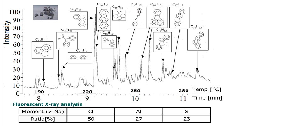
Figure 2. Gas chromatographic and Fluorescent X-ray analysis of the PC.

Figure 3. Schematic illustration of CNT growth process.
In the first position, coke is not heated for a long time, while inside it evaporates very quickly at high temperatures. Figure 7 shows SEM results of all cases. It is observed that, better result is obtained when coke is in edge of the furnace.
This phenomenon can be explained schematically with the diagrams (Figure 8). In first case excess carbon
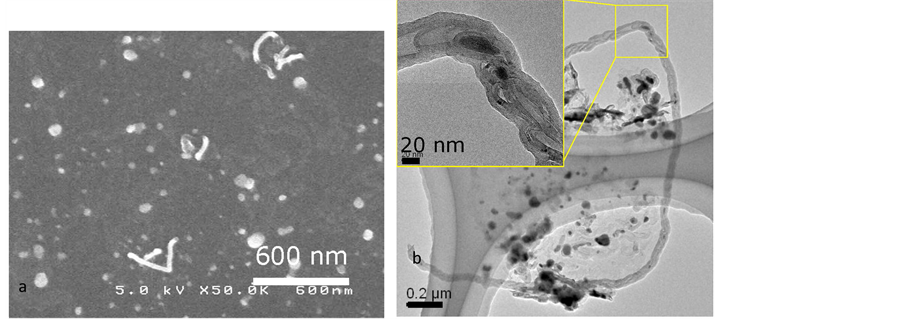
Figure 4. Gasification process under pure He (185 sccm); (a) SEM observations; (b) TEM observations.

Figure 5. Gasification process under He 105 sccm + H2 80 sccm; (a) SEM observations; (b) TEM observations.

Figure 6. PC positions in the reactor.
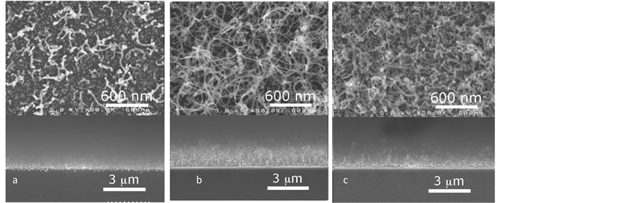
Figure 7. SEM observations of CNTs grown in cases PC is (a) outside of the furnace; (b) at edge of the furnace; (c) inside of the furnace.
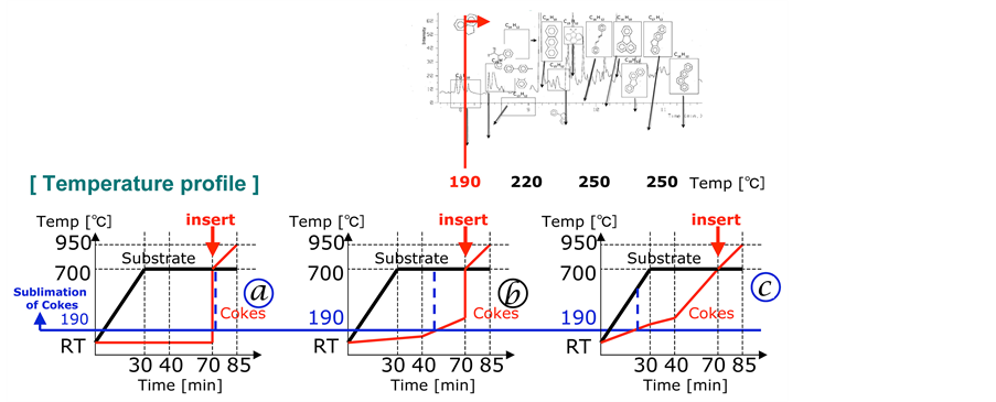
Figure 8. Schematic illustration of the processes in the reactor depending of the PC position.
was supplied in a short period and worked to deactivate the catalyst. When the coke is in edge of the furnace the moderate carbon was supplied after the substrate reached 700˚C. The diagram shows that the carbon was supplied before the catalyst was activated in the case of coke was inside of furnace.
2.3. Role and Thickness Dependence of the Catalyst
The catalyst (in this case a metal) is involved to control the kinetics of reactions such as decomposition of the precursor. It also acts as a geometric confinement for the forming CNT-structure. The catalyst can be located on a substrate or is delivered via the gas phase [24] -[26] .
The correlation between prepatterned catalyst film thickness and carbon nanotube (CNT) growth by selective area Chemical Vapor Deposition (CVD) was studied using Fe, Co and Ni as catalysts [27] [28] .
But the specific role of the catalyst in the nanotube growth process is not clear. Several growth mechanisms have been proposed, among them those where growth is expected to take place at “base” [29] and “tip” [30] locations with respect to the nanotube, have received partial evidences from experimental and theoretical studies. The main difference between them is given by the behavior of the C-metal nanoparticle during the growth process.
In this work, very thin Fe thin films were deposited on Si substrate by sputtering. Experiments show that when Fe layer thickness less than 1 nm, smallest and less quantity CNTs are grown on the substrate. Better result obtained when Fe thickness are between 1 - 2 nm (Figure 9).
In this study, we used powders (control experiment) and wet coated 0.01% 40 µl (liquid) FeCl2 as the catalyst to grow CNTs on quartz substrates. Both substrates putted in hot zone of the quarts reactor and growth temperature was 820˚C. SEM shows top views of the samples (Figure 10). Thin and spinnable CNTs are grown on thin coated FeCl2, while CNTs grown on FeCl2 powder are thicker and longer.
This unique method does not require the thin film deposition step, which shortens the time used for each batch of CNT growth [31] . The simplicity of this method allows an easy scale-up for mass production of CNTs with a low cost.
3. Conclusions
In this work, we have explored the condition for growing CNTs from petroleum cokes.
We have concluded that, the addition of H2 in the carrier gas is a key factor to grow high quantity and more strength CNTs.
Possible mechanism is to enhance the dissociation of higher order of hydrocarbon, remove carbon atoms weakly bonded on the surface of CNTs, and prevent the deactivation of the catalyst.
The control of the amount of hydrocarbon molecules from cokes is also a key factor. It is also important not to supply hydrocarbon molecules before the catalyst is activated.
Wet-coated thin films of FeCl2 work well as catalyst in the CNT growth process. This process is simplicity
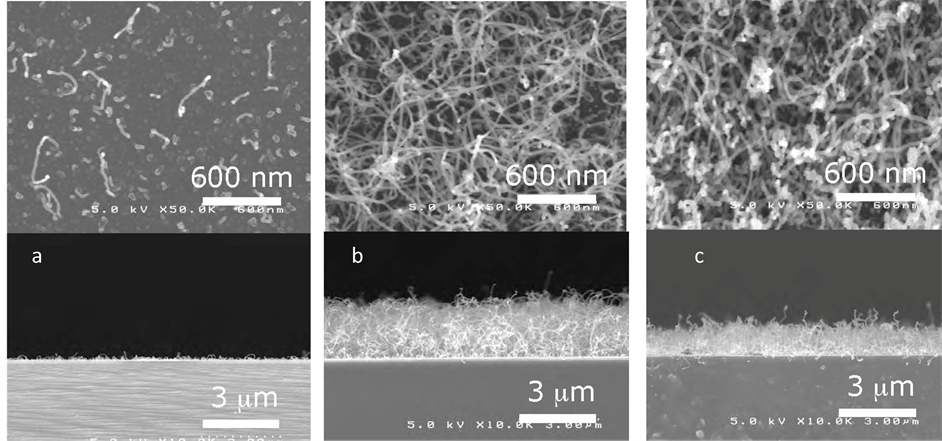
Figure 9. SEM observations of CNTs grown on: (a) 0.5 nm Fe; (b) 1.0 nm ; (c) 4 nm Fe thin films.
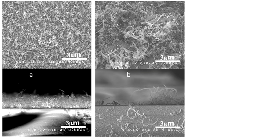
Figure 10. SEM observations of CNTs grown on (a) thin wet coated 0.01% 40 µl (liquid) FeCl2 and (b) FeCl2 powders (control experiment).
and suitable for mass production of CNTs.
Acknowledgements
Authors would like to thanks Prof. Yoshikazu Nakayama from Osaka University for discussion of the results.
NOTES
*Corresponding author.