Studies on TiO2/Reduced Graphene Oxide Composites as Cathode Materials for Magnesium-Ion Battery ()
1. Introduction
The lithium (Li) battery used as a power source because of its high specific power and high energy density. However, high demand for Li battery tends to make increase in Li price due to geographically limitedness in the earth crust [1] . As an alternative to lithium, magnesium has been foregrounded. Magnesium batteries have recently attracted great interest due to their high energy density and environmentally friendly components, coupled with magnesium’s low cost (~$2700/ton for Mg compared to $64,000/ton for Li) and abundance in the earth’s crust (~13.9% Mg compared to ~0.0007% of Li) [1] -[4] .
The major obstacles that prohibit Mg batteries from practices are 1) the kinetically sluggish Mg intercalation and diffusion in cathode materials; 2) the incompatibility between anode and electrolyte due to the high polarizing ability of the Mg2+ cation. Therefore, the search for suitable cathode and less passivated anode/electrolyte configuration is intrinsically urging [5] -[8] .
Nanostructured TiO2, an abundant, low cost, and environmentally benign material, is structurally stable during Li-ion insertion/extraction, which makes TiO2 particularly attractive for using as anode materials in rechargeable batteries. It possesses the characteristic parallel channels running along the [010] orientation, which allow easy Li+ transport and fast charging of the TiO2. In this regard, one-dimensional (1D) TiO2 nanostructure facilitates the electron transport along the long dimension and the two short dimensions ensure fast Li+ insertion/ extraction [9] -[11] . TiO2 advantages suffer from its poor electronic conductivity, and thus here are many challenges when employed in the rechargeable batteries.
Graphene, the name given to a flat monolayer of carbon atoms tightly packed into a two-dimensional (2D) honeycomb lattice, exhibits many unusual and intriguing properties in magnetic, electronic and photonic fields. In particular, its superior electrical conductivities, high surface areas and chemical tolerance intrigue great interest in energy storage technologies [9] [12] . To date, a large number of works on Li/TiO2 have been done, while TiO2 was not investigated as Mg+2 intercalation host for room temperature Mg+2-ion batteries.
Based on the above considerations, in this article, it was demonstrated a simple green route synthesis of novel TiO2 loaded by rGO. The composite was characterized by using XRD, SEM and impedance spectroscopy. Also a reaction mechanism based on the electrochemical measurements and characterization will be suggested. Solid-state Mg/PE/(0.6TiO2/0.4rGO) cell is assembled, and its cycling performances will be briefly examined to evaluate the applicability of on solid-state magnesium batteries.
2. Experimental
rGO (Electrical conductivity > 600 S/m, surface area ~457.18 m2/g) synthesized Via the reduction of Graphene Oxide have been imported from Graphenea company.
Composites of pure TiO2 anatase nanoparticles and rGO were mixed in ball mill for very short time duration. The resulted product is denoted here as 0.6TiO2/0.4rGO composites.
The electrolyte was prepared by reacting 0.1 gm of Poly (vinyl alcohol), PVA (degree of hydrolization ≥ 98%, Mw = 72,000), 1 gm magnesium bromide MgBr2 and 1 ml tetraethylene glycol dimethyl ether in distilled water.
The morphology of the polymer electrolyte was carried out using SEM (JOEL-JSM Model 5600).
The XRD patterns of the films were taken using Rigaku diffractometer type RINT-Ultima IV/S, CuKα, voltage 40 kV and 40 mA.
Conductivity measurements were made for TiO2/rGO composites by impedance method. Samples of diameter 1.3 cm were sandwiched between the two similar stainless steel electrodes of a spring-loaded sample holder. The whole assembly was placed in a furnace monitored by a temperature controller. The rate of heating was adjusted to be 2 K∙min−1. Impedance measurements were performed on Gwinstek LCR-811OG in the frequency ranging from 20 Hz to 10 MHz at different temperatures.
To form cathode pellet, a slurry obtained by mixing 0.9 gm (0.6TiO2/0.4rGO) and 0.1 g. PVA binder using magnetic stirrer hot plate (60˚C) for 2 hours is cast. The cathode is prepared by cold pressing 0.5 g. into a pellet of 13 mm diameter under 5 tons/cm2. The electrolyte is deposited on the pellet substrate with APEX spin coater at 2000 rpm. The anode was prepared by cold pressing 0.6 g. magnesium into a pellet of 13 mm in diameter under 5 tons/cm2. Two-electrodes Swagelok test cell were assembled, Figure 1, the cell was discharged at room temperature on a multi-channel battery test system (NEWARE BTS-TC35) to analyze the electrochemical responses. The current density was 50 mA/cm2 for complete discharge curve, while 25 mA/cm2 for cycling.
3. Results and Discussion
Figure 2(a) and Figure 2(b) show the SEM images of the as-prepared TiO2 and 0.6TiO2/0.4rGO composites. The SEM of TiO2 displays a surface with non-homogeneous porosity, Figure 2(a). However, (0.6TiO2/0.4rGO) composites exhibit relatively compact surface with uniform distribution of rGO on TiO2, Figure 2(b).
Figure 3 shows XRD patterns of rGO, TiO2 and (0.6TiO2/0.4rGO) composites. The XRD pattern of rGO exhibits a broad weak diffraction peak at 2q of 24.4˚ (hkl = 002) [13] , which is ascribed to disordered stacks of rGO nanosheets. The peaks of the (0.6TiO2/0.4rGO) composites can be indexed to main anatase (JCPDS NO:
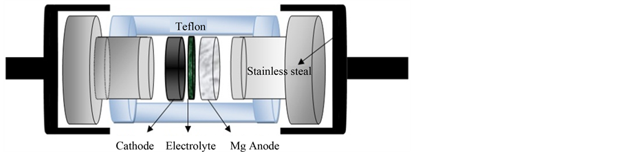
Figure 1. Schematic design of the lab cell.
 (a)
(a) (b)
(b)
Figure 2. SEM micrographs of (a) TiO2; (b) (0.6TiO2/0.4rGO).

Figure 3. XRD pattern of TiO2, (0.6TiO2/0.4rGO) and rGO.
01-089-4921) with a minor brookite phase (JCPDS NO: 003-0380). Additionally, it was observed that the (0.6TiO2/0.4rGO) composite basically retains the position of the diffraction peaks of TiO2 but the intensity decreases in 0.6TiO2/0.4rGO composite. This indicated that the incorporation of rGO considerably restrains the stacking of TiO2 layers. Furthermore, it can be hardly detected the (002) diffraction peaks of the rGO at 2q = 24.4˚ in the XRD patterns of the composite, which indicates that the rGO seldom stack during the ball mill process [11] . Furthermore, TiO2 and rGO interlace with each other to form a distinctive sandwich structure. The exfoliated TiO2 and rGO in the hybrids may provide more channels for reversible Mg2+ insertion-extraction than pristine TiO2.
The crystallite size (D) of rGO, TiO2 and (0.6TiO2/0.4rGO) composites was calculated from x-ray data using Scherrer equation as given below [14] :
D = 0.9λ/(B∙cosθ)
where 0.9 is the Scherrer constant, λ is the wavelength of X-ray, B is the breadth of the pure diffraction profile and θ is the incidence angle of the X-ray. Using this formula, the particle size of TiO2 and (0.6TiO2/0.4rGO) composites in the range 15 - 30 nm can be calculated as shown in Table1
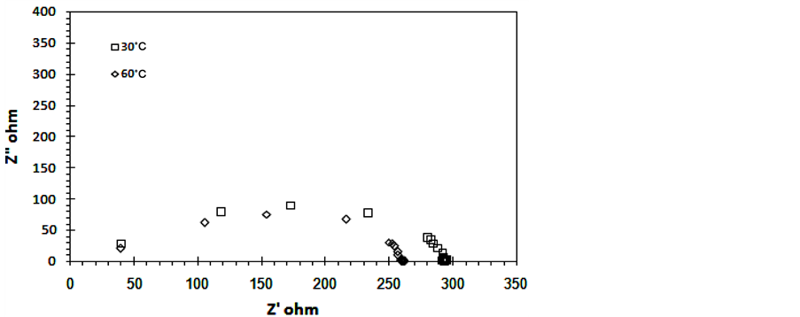
Complex impedance plot of 0.6TiO2/0.4rGO at different temperatures are shown in Figure 4(a) and Figure 4(b). The complex plot shows semicircle which correspond to the bulk resistance Rb with parallel combination of the
 (a)
(a) (b)
(b)
Figure 4. Cole Cole plots 0.6TiO2/0.4rGO composites (a) T = 30˚C, 60˚C and (b) T = 40˚C and 80˚C.

Table 1. XRD results of TiO2/rGO composites.
frequency dependent capacitance Cg. The higher the temperature, the smaller the diameter of the semicircle. The bulk resistance value Rb is determined from the low frequency intercepts on the x-axis of the complex impedance plots. The ionic conductivity is calculated using the equation 
where L is the thickness of the polymer electrolyte film, A is the surface area of the film.
The temperature dependence of bulk and ac conductivity of 0.6TiO2/0.4rGO composites is of the Arrhenius type:
 (2)
(2)
where σo in Equation (2) is a pre-exponential factor, Ea the activation energy, K is the Boltzmann constant and T is the temperature in Kelvins. Figure 5 shows ln(σ) versus 1000/T plots at different constant frequencies. The Ea values for two different thermal regions in the figure are presented in Table2 It has been found that the values of activation energy is very small relative to the value of activation energy for pure TiO2. The values of activation energy decrease with the frequency. This can be attributed to the role of electrical signal frequencies to initiate the light charge (e−).
Figure 6 shows the frequency dependence of the total conductivity for 0.6TiO2/0.4rGO composites at different temperatures. It can be noticed that the behavior follows universal power law [15] ;
 (3)
(3)

Figure 5. Temperature dependence of conductivity for 0.6TiO2/0.4rGO at different constant frequencies.

Figure 6. Frequency dependence of conductivity for 0.6TiO2/0.4rGO at different constant temperatures.
where σdc is the dc conductivity (the extrapolation of the plateau region to zero frequency), A is the frequency independent pre-exponential factor, ω is the angular frequency and n is the frequency exponent. The values of the exponent n have been obtained using the least square fitting of Equation (3) for two regions as listed in Table 2. It can be noticed that the values of n for the first region n ~ 0, frequency independent. The theoretical approaches of this behavior may be attributed to that the carriers transport takes place through infinite percolation path that can be explained by “percolation” model [16] . For the second region, relatively high frequencies, the values of n lie within the range of 0.4 < n < 0.5. The values of n, predict the domination of hopping conduction in 0.6TiO2/0.4rGO composites.
Figure 7 shows the I-V and J-P characteristics for the Mg/(0.6TiO2/0.4rGO) battery at room temperature. The I-V curve had a simple linear which indicates that the polarization on the electrode was primarily dominated by ohmic contributions [17] . The internal resistance of the battery was obtained from the gradient of the I-V curve, which was 888 W. The plot of the operating J-P suggests that the contact between electrolyte/electrodes was good. The voltage of the battery dropped to a short circuit current density of 0.13 mA∙cm−2 and the maximum power density was determined to be 0.24 mW∙cm−2.
Figure 8 shows the first discharge curve of the Mg/(0.6TiO2/0.4rGO) cell. The value of the discharge capacity С was evaluated from the equation [18] :

by integrating the area under curve of Figure 8. The surface discharge capacity estimated by 2.2 mAh for the limited electrode (0.6TiO2/0.4rGO). Figure 9(a) and Figure 9(b) show the voltage profiles during charge/discharge cycling at constant time and constant current. The operating voltage ranges from 0.5 to 4 V, and the capacity of the battery quickly stabilizes within the first several cycles. The shape of charge and discharge curves were relatively constant with cycling (50 cycles), which show that this kind of cell may be promising in reversible intercalation and de-intercalation of Mg ions. Therefore, the charge-discharge reaction mechanism of Mg/(0.6TiO2/0.4rGO) cell can be formulated as the following equations:

Figure 7. I-V and J-P curves for Mg/PE/(0.6TiO2/0.4rGO) cell.
Table 2. Electrical parameters of 0.6TiO2/0.4rGO composites.

Figure 8. First discharge curve of Mg/PE/(0.6TiO2/0.4rGO) cell.
 (a)
(a) (b)
(b)
Figure 9. Charge-discharge cycles of Mg/PE/(0.6TiO2/0.4rGO) cell (a) Cycle 3 and 4; (b) Cycle 35 and 36.

4. Conclusions
From the above findings it can be concluded that:
0.6TiO2/0.4rGO composites were synthesized by a ball mill method. SEM and x-ray analyses confirmed that reduced graphene oxide is well distributed on TiO2. These composites exhibited a reversible magnesium storage capacity and accepted cycling performance when applied as a cathode material in Mg-ion batteries. Hence, 0.6TiO2/0.4rGO is a promising cathode material for magnesium ion batteries with a promising cycling performance due to its low volume expansion upon cycling.
Acknowledgements
We are grateful to the Science technology development fund of Egypt, grant number 4758.