Triple Arthrodesis with Internal and External Fixation: Technique Paper ()
1. Introduction
With a triple arthrodesis that includes only internal fixation, the standard time for non-weightbearing ranges from 1 to 3 months with a below-knee cast which is then transitioned into a walking boot or cast towards the end of therapy [4] [5] . Patients that are kept immobile for this period of time will be at increased risk for deep vein thrombosis and muscle atrophy [4] . Patients also have a lower quality of life for this duration of time due to the long period of immobility. By mobilizing the patient immediately after surgery, the risks associated with being immobile are decreased. In addition, earlier mobility may decrease healing time, may reduce incidence of deep venous thrombosis and may increase the likelihood of the procedure being successful (due to enhanced fusion).
The triple arthrodesis technique has evolved over the past century to include Ryerson who described the classic technique consisting of joint resection of the subtalar joint, calcaneocuboid joint and talonavicular joint [1] [6] . Hoke performed the arthrodesis procedure by resecting the head of talus in order to gain access to the subtalar joint and calcaneocuboid joint [7] [8] . The modification described by Dunn included resection of the scaphoid bone and talar head [9] while Siffert et al. developed a beak arthrodesis technique to replace that of the triple arthrodesis in which cavus foot deformities could be corrected by creating a shelf in the talus thus preventing the forefoot from rising relative to the rearfoot [10] . Lambrinudi tailored the arthrodesis procedure for the patient with dropfoot. In this procedure, the talus was positioned in a dorsiflexed position while the foot was fused in a plantarflexed position [11] .
Traditional arthrodesis techniques involved joint resection with or without internal fixation. Kirienko et al. developed an operative technique where external fixation followed joint resection for the triple arthrodesis. Joint compression and subsequent fusion was achieved by introducing wires into the foot and arching the wires onto the external fixator. This arch-wire technique allowed for compression of the joints as the wires of the talus, calcaneus, cuboid and navicular were tensioned and fixated upon the external fixator [3] .
2. Materials/Methods
2.1. Pre-Operative Considerations
Clinical evaluation includes but is not limited to:
1) Post-traumatic arthritis 2) Posterior tibialis tendon dysfunction (PTTD)
3) Charcot neuroarthropathy 4) Collapsing pes planus 5) Rheumatoid arthritis 6) Degenerative joint disease (DJD) (see Figure 1)
7) Neuromuscular imbalance 8) Biomechanical deformities a) Equinovarus b) Cavovarus c) Pes planus Radiographic evaluation includes:
1) Anterior-posterior talus-first metatarsal angle 2) Talonavicular articular angle 3) Lateral talus-first metatarsal angle 4) Calcaneal inclination angle 5) Talar declination angle
2.2. Adjunctive Procedure
Tendo Achilles Lengthening
Anequinus component to the patient’s lower extremity deformity requires a tendo Achilles lengthening. If deemed necessary, this procedure is performed prior to the dissection for the triple arthrodesis. Equinus is checked by placing the patient’s subtalar joint in the neutral position and dorsiflexing the ankle with the knee flexed at 30 degrees to eliminate the soleus influence and then with the knee fully extended. If equinus is present with the knee flexed and extended, a tendo Achilles lengthening is performed percutaneously with 3 transverse incisions, one lateral and two medial. The first incision is 2 cm proximal to the insertion at the calcaneus and each incision is performed directly over the tendon and is 1 cm apart. The blade is inserted parallel to the tendon fibers and then turned 90 degrees. The tendon is stretched, thus improving foot dorsiflexion. Incision sites are then re-approximated.

Figure 1. Pre-operative radiographs of patient with DJD.
2.3. Dissection
The incision sites of the foot are first marked with a marking pen. The lateral incision is marked 1 cm posterior to the lateral malleolus and then curved around the calcaneocuboid joint dorsally and onto the base of the fourth metatarsal. The medial incision is then marked 1 cm anterior and dorsal to the medial malleolus and extended distally to the talonavicular joint. The lower limb is exsanguinated with use of an Esmarch bandage and a thigh tourniquet is inflated to 350 mmHg. If a tendo Achilles lengthening is needed, it is performed at this time as described above. The procedure can begin either medially or laterally as per surgeon’s preference. With the use of #15 blade, the medial incision is made through the skin (see Figure 2). The incision is carried down to subcutaneous tissue with use of either sharp and/or blunt dissection. At this level, the tibialis anterior tendon and great saphenous vein proximally and the tibialis posterior tendon distally along with other vital neurovascular structures must be retracted away from the surgical site. All periosteal, ligamentous and capsular structures are reflected from the talonavicular and subtalar joints with use of a periosteal elevator as well as with the use of sharp
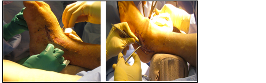
Figure 2. The medial incision (left). Lateral incision as per Ollier’s technique (right).
dissection to gain access to articular surfaces.
A bone curette is utilized to excise the entire cartilagenous surfaces cartilages from the head of the talus and the proximal articular surface of the navicular with care taken to prevent gouging of the joint. A saline-moistened gauze is then placed over the medial incision site so now attention may be directed to the lateral aspect of the foot. The lateral incision is made through the skin and carried down to subcutaneous tissue with use of either sharp and/or blunt dissection (see Figure 2). At this level, the peroneal tendons (most notably the peroneus tertius) and the sural nerve are identified and must be retracted away from the surgical site along with any other vital neurovascular structures. The Extensor Digitorum Brevis (EDB) muscle is identified and then transected at its origin in the sinus tarsi in order to better access the area. The bifurcate ligament is identified and resected. The fibro-adipose block in the sinus tarsi is excised with use of rongeur. All periosteal, capsular and ligamentous attachments are then resected thus exposing the calcaneocuboid joint and talonavicular joint laterally and the posterior facet of subtalar joint laterally. A malleable retractor is then applied to connect both the medial and lateral incisions, thus lifting the skin dorsally and protecting the neurovascular and vital tendinous structures (see Figure 3).
Utilizing a lamina spreader, the subtalar joint is distracted thus exposing all articular facets (see Figure 3). With this exposure, the interosseous talocalcaneal ligament is identified and transected from its attachment. At this time, a bone curette is used to remove all the remaining cartilage from the subtalar joint, which includes the posterior and middle facets. The cartilage at the head of the talus that articulates with the navicular is excised with a bone curette. Attention is then directed to the calcaneocuboid joint where the cartilage is excised in the same fashion. The joint surfaces are then irrigated well with sterile normal saline to flush the incision sites and cleanse them of cartilaginous debris. Flushing the incision sites thoroughly is of vital importance because remnants or debris that remain in the posterior facet or ankle joint can result in the patient experiencing unexplained post-operative pain and/or incomplete apposition at the previous articulation sites and prevent fusion. It is important to fenestrate the surface of the joints, in order to help aid the fusion process. A 1.6 mm drill is used to perform subchondral drilling at all joint surfaces. Prior to screw placement, approximately 10 cc of demineralized bone matrix is placed carefully over and around the joint surfaces.
2.4. Application of Internal Fixation
The foot is then placed into the neutral position and then verified with intraoperative fluoroscopy. Once the calcaneus is properly positioned, a guide wire for the 6.5 mm headed, cannulated, short-thread, cancellous, bone screw is driven under fluoroscopy from the body of the calcaneus through the body of the talus with care taken to encompass the posterior facet of the subtalar joint. The countersink is then applied over the guide wire and cannulated measure is then employed to verify length of screw needed. The screw is placed over the guide wire and inserted across the fusion site. It is checked under fluoroscopy to ensure that all threads are distal to the articular surface. Care is taken to ensure no threads cross into the subtalar joint or into the ankle joint. Next, a 5.0 or 5.5 mm (depending on the size of the bone) headed, cannulated, partially-threaded, cortical bone screw guide wire is placed from the navicular into the talus. The countersink is then applied over the guide wire and cannulated measure is then utilized. The screw is placed over the guide wire and inserted across the fusion site. It is checked under fluoroscopy to ensure that all threads extend beyond the previous articulation site. Next, a 5.0 or
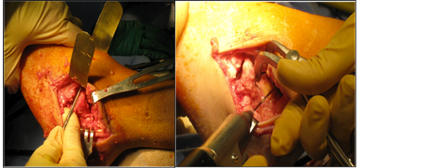
Figure 3. Resection of the subtalar joint, talonavicular and calcaneocuboid joints laterally and medially.
5.5 mm (depending on the size of the bone) headed, cannulated, partially-threaded, cortical bone screw guide wire is placed from the cuboid into the calcaneus. The countersink is then applied over the guide wire and the measure is then utilized to obtain the correct length. The screw is then placed over the guide wire and inserted across the fusion site. It is checked under fluoroscopy to ensure that all threads pass distal to the fusion site. All fixations are checked under fluoroscopy to verify proper positioning over the arthrodesis sites (see Figure 4).
All incision sites are then flushed with copious amounts of normal sterile saline. Layered wound closure is performed to ensure a more secure closure. At this level, it is important to cover all exposed bone and hardware to minimize dehiscence. The thigh tourniquet is then released to ensure vascular status is intact to the lower extremity. The skin is then re-approximated.
2.5. Construction of the External Fixator
The external fixator for a triple arthrodesis is constructed with a footplate, matching plate, proximal ring and 4 columns or threaded rods per block. The author prefers to use carbon fiber rings with Radel columns to allow maximum radiolucency (see Figure 5).
2.6. Application of External Fixation/Wire Insertion
After the incision sites are sutured, the tourniquet is deflated and the vascular status is determined to be intact, the external fixator (MDPO Systems, Sunrise, FL) is applied to the lower extremity and transosseous wires are placed as indicated by Catagni [12] and Kirienko et al. [3] . First, the surgeon must center the leg in the ring and center the foot in the footplate. The tibial tuberosity is aligned with the second digit in the three body planes. It is imperative to place the foot straight with the tibia and underneath the leg. Intra-operative fluoroscopy is used to check alignment. It is important to keep the knee positioned in the frontal plane to avoid rotation of the frame. In addition, it is essential to leave two-finger width of space between the soft tissues at the proximal ring and three-finger width at the matching plate in order to account for soft tissue swelling posteriorly. Before wire placement, it is necessary for the surgeon to identify and understand the safe zones of the leg, ankle and foot. It is also important to note that each wire should be driven through two bone cortices (bicortical) and that the wires should converge (see Figure 6). It is the surgeon’s preference to use either smooth or olive wires versus half pins at each segment, as both will maintain stability. The only difference is that when performing the arch-wire technique [3] , a smooth or olive wire would need to be used for optimal compression.
The first reference calcaneal wire must be parallel to the footplate and perpendicular to the calcaneus is placed as close to the pre-fabricated arches as possible. The matching plate is positioned proximal to the ankle joint and the footplate is kept proximal to the inferior calcaneal tuberosity 1.5 - 2.0 cm to allow for weightbearing (see Figure 7). The smooth or olive wire must then be tensioned approximately 70 - 90 kg after the nut and fixation bolt on the opposite side of the tensioner is tightened [2] . Next, the proximal tibial smooth or olive wire is placed parallel to the ring and perpendicular to the medial face of the tibia (see Figure 8). This wire is secured

Figure 4. Intraoperative fluoroscopy illustrating guide wire placement for internal fixation (left). Intraoperative fluoroscopy of the internal fixation in place (right).
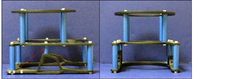
Figure 5. The components of the triple arthrodesis frame. Note the arch column (arrow).
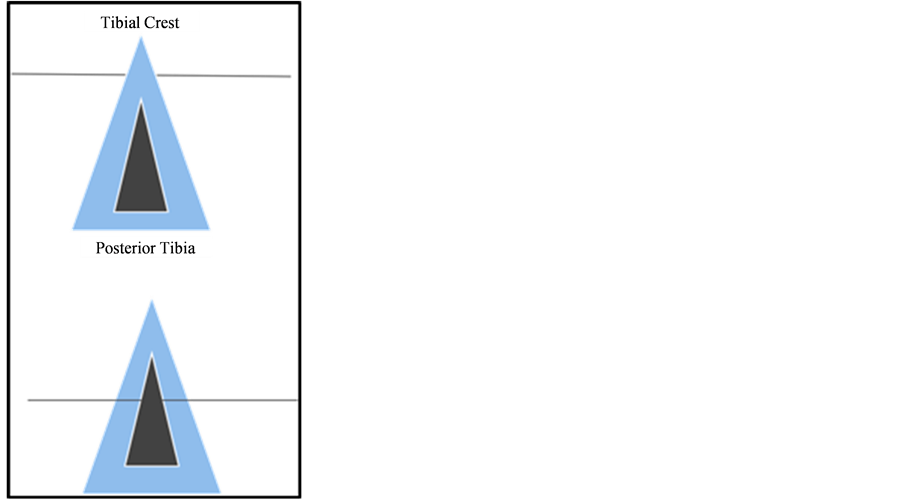
Figure 6. Do not drive wire unicortical (top). Wire should be driven bicortical (bottom).

Figure 7. Calcaneal wire placement with the heel approximately 1.5 - 2.0 cm plantarly in order for the patient to ambulate post-operatively.
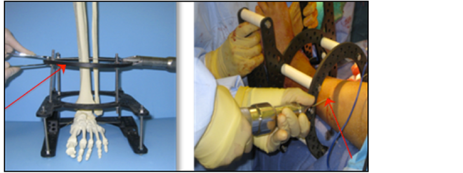
Figure 8. Frontal plane wire placed parallel to the corresponding ring and perpendicular to the medial face of the tibia.
and tightened with a nut and fixation bolt and then tensioned on the opposite side to 110 - 130 kg (the wire should be parallel to the reference calcaneal wire). At this point, the frame can now be shifted from medial to lateral to ensure the leg is centered within the frame. Intra-operative fluoroscopy may be used to confirm the proper orientation of the rings and wires to the limb. The remaining wires are placed per author’s preference, but it should be known that the wires can be placed per the surgeon’s choice in no particular order as long as all wires driven are kept within the safe zones and follow standard technique.
The second frontal plane wire placed is a smooth or olive wire at the level of the matching plate oriented slightly anterior-superior to posterior-superior to the arch column (see Figure 5). Following placement of this wire, the fixation bolt and nut are tightened and the opposite side is tensioned to 90 - 110 kg. At this point, the rings are now ready to be locked. The proximal ring smooth or olive wire is then placed from the posteriormedial to anterior-lateral direction (the wire is guided by placement along the medial face of the tibia and driven bicortically through the lateral tibia), keeping the safe zones in mind. The wire is then secured and tensioned as previously discussed. The subsequent matching plate smooth or olive wire is then driven posterior-inferior to anterior-inferior to the arch column, and secured and tensioned as previously discussed (see Figure 5).
The talar wire is positioned in order to compress the subtalar joint (see Figure 9). The wire is oriented along the medial talar body towards the lateral talar process. The anatomical arches of the MPDO footplate will guide the surgeon to properly position the wire. When the wire is bent, it will create compression force perpendicular to the subtalar joint. It is important not to catch the fibula with this wire in order to prevent motion of the wire due to its muscular attachments. The wire ends are then moved posteriorly, approximately two holes from where it naturally lies and the fixation bolt is placed on the lateral side with minimal tension medially (approximately 30 - 50 kg) (see Figure 9). An olive wire can be used in place of a smooth wire at this level with the olive located lateral in order to shift the talus posteriorly.
The midtarsal wire is then placed to compress the talonavicular and calcaneocuboid joints. The wire is directed along the medial navicular tuberosity towards the lateral cuboid. The anatomical arches will guide wire placement as they mimic the natural arch of the midfoot (see Figure 10). At this level, the wire is arched and secured two holes proximally. The compression force placed at the calcanecuboid joint and talonavicular joint by this wire will not affect the compression force of the talar wire [2] . The wire is then tightened with a fixation nut and bolt laterally with minimal tension (approximately 30 - 50 kg) applied medially to this wire. Using the footplate arches as a guide, the surgeon can precisely place a smooth or olive wire versus building up arches with posts and/or other components. As a result, the arches and the subsequent exact wire placement create optimal compression with ease at the subtalar joint, calcaneocuboid joint and talonavicular joint. Again, an olive wire can be used in place of a smooth wire, with the olive being placed laterally and tensioned medially for shifting of the joints in a more medial direction.
The second calcaneal wire is then placed from proximal-lateral to distal-medial with the posterior calcaneal tubercle being the reference point. The wire is tightened and tensioned as previously discussed at 70 - 90 kg. Lastly, the midfoot (metatarsal) wire is inserted from medial to lateral and placed distal to the bent compression wire. The wire is secured to the footplate with a fixation bolt and nut and then tensioned on the opposite side at 50 kg. This wire should encompass at least 3 metatarsal shafts (see Figure 11). Intra-operative fluoroscopy is then used to verify placement of all wires (see Figure 12).
3. Conclusion
Triple arthrodesis with internal and external fixation may provide a decrease in healing time and may decrease complications associated with non-weightbearing as the patient ambulates during the post-operative course. The application of an external fixator manufactured with prefabricated arches along with the resulting weightbearing

Figure 9. The talar wire (left) oriented along the medial talar body towards the lateral talar process. The wire ends are then moved posteriorly, approximately two holes from where it naturally lies (right).

Figure 10. The midtarsal wire is placed along the medial navicular tuberosity and towards the lateral cuboid. At this level the wire is arched and secured two holes proximally.
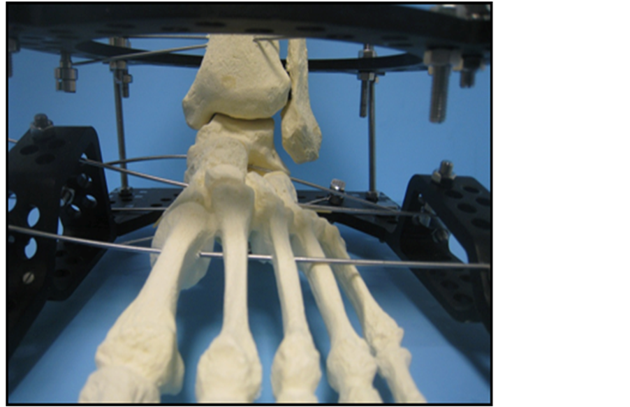
Figure 11. The midfoot (metatarsal) wire should encompass at least 3 metatarsal shafts.
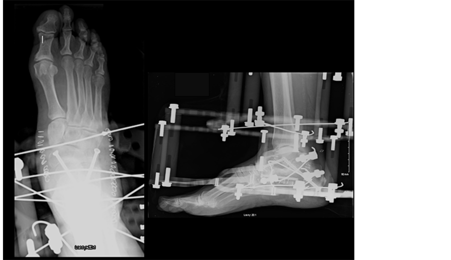
Figure 12. Post-operative radiographs showing internal and external fixation of triple arthrodesis.
forces due to patient mobility allows compression at the subtalar joint, calcaneocuboid joint and talonavicular joint. The technique of using external fixation along with internal fixation is a novel modification to the published triple arthrodesis procedures.
NOTES
*Corresponding author.