Combinational Optimization of Strut Placement for Intracranial Stent Using a Realistic Aneurysm ()
1. Introduction
Stroke is a cerebrovascular disease with high mortality that leads to a serious decline in the quality of life. Cerebral aneurysm, a vascular disorder characterized by distension of the vessel wall, is known as a main factor of stroke. It mainly occurs at arterial curves and bifurcations in or near the circle of Willis. Blood flow dynamics is thought to affect its initiation, growth, and rupture behaviors.
For treating such vascular disease, endovascular treatments have been valued as a minimal invasive therapy in recent years. A modern technique treating cerebral aneurysm is the insertion of a medical device called a flow diverter stent.
The aim of flow diverter implantation is to reduce the flow in an aneurysm by covering an aneurysm orifice. Flow stagnation, produced by the fine mesh structure of the diverter, is thought to promote blood clotting in an aneurysm. However, apart from its potent effect on flow reduction, the insertion of the metal device poses the risk of occlusion of a parent artery [1] . One strategy for avoiding the risk of arterial occlusion is the use of a device with a higher porosity, of approximately 70%.
The effect of a flow diverter on flow has been studied both experimentally and computationally [2] . Previous studies have shown the change in flow pattern in an aneurysm following stenting using several stent designs [3] -[5] . These results suggest that the design of the stent mesh affects the flow reduction as well as stent porosity. Owing to these reports, the search for an optimum stent design has received increased attention in recent years.
One approach for obtaining a flow-reducing stent design is shown in [6] . In this approach, the authors introduced the concept of bundle of inflow (BOI), which is the local narrow inflow entering an aneurysm. BOI is visualized as a region of streamlines entering an aneurysm and is the region affecting a circulation in an aneurysm. The design is based on the observation of BOI; to reduce the aneurysmal flow, the stent should interrupt BOI. The strut placement in BOI shows a velocity reduction of 26% with a single strut and 41% with two struts. This study investigated only one and two struts. Further studies using several struts are required.
Optimization is a well-known method of searching design space in several research and industrial fields. Given that the aim of stent insertion is to reduce flow, optimization is applied using computational fluid dynamics (CFD) analysis. Srinivas et al. [7] applied an optimization procedure to determine the best stent structure across the neck of a 2D aneurysm using Latin hypercube sampling and kriging. Nakayama et al. [8] investigated the size of a strut for a stent with 80% porosity using a multiobjective genetic algorithm and kriging.
These optimization strategies required numerical models. Indeed, all stent designs required manual mesh generation, making it almost impossible to identify an optimal design by an automatic process.
We have accordingly developed a procedure for automated optimization of stent design using a combination of the lattice Boltzmann (LB) method and simulated annealing (SA) [9] . Our approach can identify an optimal stent in a completely automated manner. The stent was constructed as a combination of struts. And the combination of struts location was searched under the condition of 80% porosity to minimize the average velocity in an aneurysm. The results suggest that an initial geometry similar to that of the optimal design can save the computational time required to obtain an optimal stent.
This paper describes the design optimization of stents using a realistic aneurysm. We present the characteristics of an optimal stent in comparison with our previous report [6] from the perspective of the BOI model.
2. Method
2.1. Numerical Simulation on Aneurysmal Flow
Figure 1 shows the realistic saccular aneurysm used in the present study. The aneurysm was located on the basilar artery, and the 3D structure was obtained from medical imaging. Informed consent was obtained from the patient.
CFD was performed using the open-source LB solver Palabos, version 1.4 [10] . The LB method for hydrodynamics is a mesoscopic approach in which a fluid is described in terms of density distribution  of idea-

Figure 1. Image of realistic aneurysm for numerical simulation. This picture is by courtesy of ASME DC, FEDSM-ICNMM2010-30591.
lized fluid particles moving and colliding on a lattice. Here,  and
and  denote a lattice site and time, respectively. The LB method usually uses the Cartesian mesh, and it can switch the definition of each node between solid and fluid. Therefore, it can easily automate the process of optimization by avoiding the manual mesh generation. We applied a single-time BGK relaxation method [11] . The collision-propagation dynamics are written as follows:
 (1)
(1)
where  is called the local equilibrium distribution. The quantity
  is called the relaxation time.
Several studies have used the LB method to analyze aneurysmal flow, showing the adequacy of LB simulations and the application to a complex problem in a living system [12] -[16] . In addition, several studies have compared the LB method with the conventional finite-volume method (FVM) [12] [17] [18] .
Computational domain boundaries were derived from the surface description of the aneurysmal geometry provided by the STL format. Thus, in principle, our strategy can be applied to any aneurysm geometry. We imposed D3Q19 lattice topologies; the use of a regular lattice is helpful for automatic handling of the construction of stent geometry and numerical meshing, as described in our previous study [9] .
The spatial discretization  was set at 0.05 mm. We verified that doubling the mesh resolution modified the average velocity by less than 5% and did not change the flow pattern. The number of lattice sites for each model was 1.6 million. Flow simulations were parallelized with 72 cores during all the optimization processes.
2.2. Flow Conditions
Flow condition contained a lot of assumptions and basically corresponded to the previous studies [6] . Assuming intracranial flow, the inlet boundary was assumed as a parabolic velocity boundary with an average velocity U of 0.205 [m/s]. At the outlet, a constant pressure boundary was imposed. To achieve a Reynolds number of 200, the kinetic viscosity  for LB simulation was chosen as 0.0267, giving the relaxation time
  of 0.58 [11] [19] . Reynolds number of 200 was chosen to compare the flow to our previous study using same aneurysm. Given that the Reynolds number ranges from 110 to 850, a non-Newtonian effect can be neglected [20] . In this study, we used a basilar artery with a diameter of 3.9 mm and the Reynolds number of 200. Therefore we used Newtonian assumption. And we may simplify the fluid conditions as isothermal and incompressible. A steady state is assumed to be reached when the standard deviation of the average kinetic energy becomes less than 1.0 ´ 10−5. To impose no-slip boundary conditions on the wall of the vessel and the aneurysm as well as on the stent struts, the so-called bounce-back rule was imposed. The walls of the aneurysm and the stent struts were assumed as rigid.
2.3. Optimization of Strut Combination
The algorithm for stent shape optimization was the SA approach [21] -[23] . SA is a classical probabilistic metaheuristics applicable to hard optimization problems [24] [25] . It emulates the physical phenomena of cooling of a molten metal and can identify a good approximation of the global optimum in a large search space. We initially set a high temperature and then slowly lower it as the algorithm runs. At the beginning of the process, the temperature is high and structural change occurs frequently. As cooling proceeds, the probability of change decreases.
The SA process was performed with application of random modifications of the current stent geometry to minimize the average velocity Vave inside the aneurysm. Though CFD was highly parallelized, optimization was performed by serial processing. The stent structure underwent gradual changes during the optimization process as modifications were accepted or rejected. The probability of acceptance of a modification was calculated by the variation of Vave and temperature T as follows:
 (2)
(2)
where  and
and  denote the average velocity in the current and previous states, respectively, and
  denotes a random number between 0 and 1. As the SA proceeded, T was gradually reduced using the following equation:
 (3)
(3)
where  = 0.9 [23] . Thus the acceptance probability of stent modification gradually falls with
 . In our case, the initial temperature was selected as 1.0 ´ 10−2 to give an acceptance probability of 0.5 at the starting optimization. The process was halted when the temperature became less than 1.5 ´ 10−3 to avoid endless iterations. The number of stents evaluated in this process was 200.
The stent geometry was defined only in the plane of the aneurysmal neck. For automation of stent modification, the stent consisted of unconnected struts, as illustrated in Figure 2. The size of struts was 0.07 × 0.07 × 0.71 [mm], with each strut occupying 1% of the neck area. The location of struts was limited to 49 points distributed around the neck. Because of the asymmetry of the neck, the square area where a strut can be placed also covers the outside of the neck. Two strut orientations were allowed:  and
and . The initial struts were placed at the end of the square with the uniform orientation of
 , as shown in Figure 3(a) and Figure 4(a).
We performed the optimization of strut combinations with two and twenty struts, corresponding to porosities of 98% and 80%, respectively.
Stent evaluation was based on the reduction ratio of the average velocity in the aneurysm, as follows:
 (4)
(4)
where  denotes the average velocity without the strut.
3. Results
We selected several numerical results obtained during the optimization process to show the influence of strut placement on the BOI. Table 1 shows the average velocity in the aneurysm and  corresponding to each strut configuration. Figure 3 and Figure 4 show the positions of struts on the neck (left panel) and the streamlines entering the aneurysm as BOI (right panel), respectively. Figure 3 illustrates the results with 98% porosity as case A, and Figure 4 illustrates those with 80% porosity as case B.
3.1. Optimization with 98% Porosity Struts
As shown in Figure 3(a) as case A-1, the initial struts for 98% porosity were located outside the neck area. The initial stent accordingly yields 0%  and the flow pattern is the same as the flow without struts. The streamlines make a bundle in the parent artery and enter the aneurysm along the neck wall. The area of BOI on the neck is located on the outer area of the arterial curve. The flow rotates in the aneurysm and exits through an area
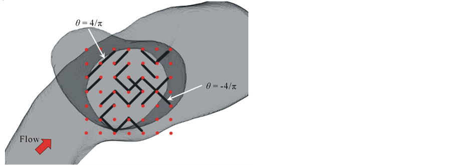
Figure 2. Schematics of stent model consisting of unconnected struts. Black line represents a strut, and red point represents possible site of strut. Strut can have two types of orientations.

Figure 3. Position of strut and BOI with 98% porosity. Left figure shows the position of struts, and right shows the streamlines entering the aneurysm. Green area represents the BOI area.
larger than the BOI area.
Case A-2 shows the result of the best  during optimization (Figure 3(b)). We call this stent the optimal stent. The position of the BOI area is the same as that in the case without struts. The struts have been moved into

Figure 4. Position of strut and BOI with 80% porosity. Left figure shows the position of struts, and right shows the streamlines entering the aneurysm. Green area represents the BOI area.

Table 1. Flow reduction by each struts placement.
the neck. Moreover, both struts are located in the BOI area on the neck. The struts separate the flow; the streamlines going around the struts and those going through the gap between the struts reach the top of the aneurysm, similar to the streamlines without the strut. The other streamlines hit the neck wall and immediately exit the aneurysm without rotating.  is improved to 26%.
Figure 3(c) as case A-3 shows one of the stent models obtained in the optimization process. One strut lies in BOI and the other one lies outside the neck. The orientation of the strut is the same as that in Figure 3(b). A change in the flow direction by the strut is also observed. However, the strut’s effect such as the velocity reduction around the struts and the number of streamlines hitting the neck wall is moderate compared to case A-2.  reaches 18% with one strut.
Figure 3(d) also shows one of the stent models as case A-4. One strut is located on the neck but outside the BOI area, and the other strut is located outside the neck. The flow pattern in the aneurysm is similar to the flow without struts, and  is 4%
is 4%
3.2. Optimization with 80% Porosity Struts
As case B-1, the initial struts with 80% porosity are distributed inside and outside the aneurysmal neck, as shown in Figure 4(a). Most struts are distributed on the outflow area, and there are no struts on the BOI area. The struts lead to  of 22% before optimization.
Figure 4(b) shows the flow after optimization as case B-2. The struts are concentrated in the BOI area, and some struts are located in the outflow area and outside the neck. An inflow perpendicular to the neck plane is observed through the gap between the struts. The inflow reduces its speed, and most streamlines exit the aneurysm without rotating.  reaches 68%.
As case B-3, a strut distribution with a large pore in the BOI area shows a smaller influence on aneurysmal flow, as shown in Figure 4(c). The struts are distributed around the neck; however, there are few struts in the BOI area. The flow pattern is relatively similar to that with initial struts, and  is 23%.
4. Discussion
We present the first report of strut optimization using a realistic aneurysm. Even in a realistic geometry, our optimization program improves  and generates a nonuniform strut distribution as the optimal stent model. We previously studied CFD using a realistic aneurysm and reported that the BOI area could be an optimal location for strut placement [6] . To confirm the present results, we compared both
  and strut distribution with those observed in the previous study.
The previous study showed strut placement based on the flow pattern around the aneurysm. The position was predicted on the basis of BOI observation using a 3D visualization system. A single strut covered the neck area by 2%. Thus, our results for case A with 98% porosity correspond to the single-strut placement. The strut was located in BOI in the previous study; a strut outside BOI showed a smaller reduction effect. The result suggests that strut placement inside BOI is important for reducing aneurysmal flow.
In the present case, both optimal struts in cases A-2 and B-2 show a concentration of struts in the BOI area, and case A-2 shows  of 26% of average velocity in the aneurysm. The previous study showed
  of 27% with one strut. Figure 5 shows the position of struts and the streamlines around the aneurysm in our previous study. Comparing it with Figure 3, both cases have struts in the BOI area on the neck. Though the sizes and angles of the struts are different, both struts in Figure 3 and Figure 5 disturb the inflow entering the aneurysm and part of the streamlines hits the neck wall. Thus, both struts in BOI have the same effect of changing the flow direction and reducing the aneurysmal flow. The present results are thus consistent with those of the previous study and suggest the potent effect on velocity reduction of strut placement in the BOI area.
As shown in Table 1, strut placement in the BOI area can increase . Though the movement of strut is completely at random during the SA process, once a strut locates in the BOI area, the movement of strut outgoing from the BOI becomes hard to be accepted according to Equation (4). On contrast, the movement of strut entering the BOI area can easily accepted. Therefore, the struts tend to concentrate in the BOI area during the SA process.
To quantitatively estimate the effect of a stent, optimization should be applied for each aneurysm. In general, aneurysm geometry and flow conditions are specific; therefore, the effect of the optimal stent is expected to vary depending on the case. In our case, the porosity of 80% shows  of 68%. In several studies, velocity reduction

Figure 5. Position of strut and the BOI around the aneurysm with a strut in previous study. Left figure shows the position of strut, and right shows the streamlines around the aneurysm by courtesy of ASME DC, FEDSMICNMM2010-30591. Green area represents the BOI area.
increased with decreasing porosity [26] -[28] . In our case, decreased porosity led to an increased . However, the rate of velocity reduction is expected to differ from that in those studies because our strategy produces a nonuniform distribution.
The total number of possible stent geometries is some 5000, even with 98% porosity. It is effectively impossible to perform an exhaustive search over all combinations. We evaluated some 200 modifications for each porosity using 300 h of computational time with 72 cores. The result of optimization in a 2D aneurysm showed a rapid improvement of stents at the early stage of optimization and saturation at the middle and final stages [9] . According to these findings, an increase in cases for optimization may slightly improve . However, the characteristics of an optimal stent are consistent even after longer optimization.
We constructed a stent model as a combination of disconnected struts in the neck plane. In general, a stent has a curved structure along the curve of the parent artery. The optimal stent will accommodate the flow pattern along the curved surface, provided that the stent model is built on the curved surface. Disconnection of struts can lead a localized concentration of struts in the BOI area. The results suggest that struts in BOI exert a potent effect on velocity reduction. However, disconnection of struts will lead to difficulty in manufacturing. For a realistic situation, a constraint of stent design to retain connections between struts will be required. However, under the concept of BOI, a realistic stent with connected struts will have the common characteristic of BOI disturbance.
The choice of objective function is a challenge for optimization studies. The aim of flow diverter treatment is to reduce aneurysmal flow and promote blood clotting. Although there are several functions for evaluating stent performance [29] -[31] , the critical objective of aneurysm treatment remains unclear. We previously selected the average velocity in an aneurysm as an objective, according to the objective used by Srinivas et al. and Nakayama et al. [7] [8] . However, these studies showed various stent designs associated with the objective. Although the selection of objective functions must be considered, our approach can be applied with any objective function such as WSS and vorticity.
Finally, the flow is simplified as steady and Newtonian. The definition of inlet velocity with Reynolds number of 200 is in the range of intracranial flow presented in MR imaging of Isoda et al. [32] . Liou et al. [33] suggested that the characteristics of aneurysm inflow and outflow area under the steady-state condition are consistent with those under the pulsatile condition, except for small differences. And Newtonian-fluid assumption does not greatly affect the global aneurysmal flow obtained with the non-Newtonian model, confirming previous studies [34] -[36] .
5. Conclusions
In conclusion, we performed optimization of strut placement in a realistic aneurysm with several porosities. After the optimization, struts show concentration in the BOI area and disturb the inflow entering the aneurysm in all cases. In a stent of 98% porosity, the results are similar to those of our previous study; the strut is placed in BOI and the average velocity reduction is 26%. The result for 80% porosity shows nonuniform distribution and 68% average velocity reduction.
The nonuniformity of the optimal design suggests that the use of a localized concentration of struts as the initial condition can save computational time for reaching the optimum.
Acknowledgements
This study was supported by a Research Fellowship of the Japan Society for the Promotion of Science for Young Scientists and partially supported by the Ministry of Education, Science, Sports and Culture, Grant-inAid for Scientific Research (B), 2013-2015(25282140, Makoto Ohta). This work was done in collaboration with the European VPH project THROMBUS FP7-ICT 269966. The authors thank Enago (www.enago.jp) for the English language review. Finally, the authors acknowledge ASME for the use of figures in the ASME conference paper FEDSM-ICNMM2010-30591.