Zirconium Modified Aluminide Coatings Obtained by the CVD and PVD Methods ()
1. Introduction
The improvement of engine turbines efficiency is achieved by the use of effective cooling systems of turbine blades and by diffusion protective coatings on nickel-based superalloys [1-3]. Alloyed nickel aluminides are of particular interest for use as bond coats in thermal barrier and environmental barrier coating systems, due to their strengths and abilities to form a protective aluminide oxide layer. It is the aluminum oxide layer that limits the amount of oxygen that can diffuse into critical engine components causing a catastrophic failure. This layer is also one of the most critical components of a thermal barrier (TBC) system. TBCs are used to protect superalloy engine components from the harsh environments that they are exposed to as a result of operation in gas turbine engines. Temperature in these engines can exceed 1650˚C and metal temperature can reach 1200˚C. TBCs insulate the superalloy, thus allowing engines to work at higher temperature with higher efficiency [4-8]. Oxidation of the bond coat is a primary failure mechanism of commercial TBCs and a potential weak link for improving coatings lifetime. In most cases, bond coats are designed to form an external protective α-Al2O3 scale during high temperature operation. Adhesion of this thermally-grown scale is necessary to maintain the ceramic top coat. Any spallation of the alumina scale results in loss of the overlying ceramic coating.
Numerous factors affect adhesion of the α-Al2O3 scale to the metal substrate [9]. One of them is a chemical composition of the coating. Addition of small amounts of reactive elements such as Zr, Hf, Y, or Ce, Pt to aluminide coatings has beneficial effects on their oxidation behavior [9]. These beneficial effects include improvement of adhesion of alumina scales and reduction of oxide scale growth rate which results in elongation of the coating and TBC lifetime [9-12]. Zirconium co-deposited with aluminum on the nickel superalloy by the CVD process was developed by Onera and Snecma [22]. Zirconium provided by the ZrCl2∙8H2O activator [13] locates far below the coating surface, at the interface between the β-NiAl coating and the interdiffusion zone. This interface corresponds to the initial surface of the superalloy and zirconium deposition occurs at the beginning of the process. The interdiffusion zone consists of the β-NiAl matrix and phases containing additional elements of the superalloy (Cr, Co, W, Al, Ti, Mo) [13]. During oxidation, zirconium migrates towards the surface and the Zr distribution in the whole oxide layer becomes homogeneous. Zirconium may migrate via NiAl grain boundaries, where it is known to segregate [14]. Thus, Zr present in the oxide can be expected to modify the stress relief by reducing the oxide creep rate. Zirconium delays the oxide scale spalling and inhibits the formation of cavities at the metal/oxide interface. There is no voiding at the metal/oxide interface, unlike in Ptmodified NiAl coatings [13]. The absence of voiding in the presence of Zr is expected to improve alumina adhesion on the nickel aluminide [13].
Several techniques have been employed to deposit NiAl coatings [15]. Two of them are: the electron beam physical vapor deposition (EB-PVD) [16,17] and the chemical vapor deposition (CVD) methods [18-21].
In this study, the structure of zirconium-modified aluminide coatings deposited by these two methods on pure nickel is analyzed.
2. Experimental
The commercial nickel of 99.95% wt purity was used in this study. The cylindrical samples of the 20 mm diameter and 4 mm high were cut and grounded up to SiC No 1000, degreased in ethanol, ultrasonically cleaned and finally aluminized.
The aluminide coatings were made using the CVD equipment BPXPR0325S manufactured by IonBond company (Figure 1). The aluminizing process was conducted for 2 h [21] and 5 h. Aluminum chloride vapor (AlCl3) was produced in an external generator I (Figure 1), at 330˚C according to the reaction: 2Al + 6HCl®2AlCl3 + 3H2. Then the saturating atmosphere was transported in a stream of hydrogen gas into the CVD reactor, where nickel samples were placed. The AlCl3 vapor reacted with the nickel and grains of intermetallic phase NiAl were formed according to the reaction: 2AlCl3 + 2Ni +

Figure 1. An equipment for the CVD method.
3H2®2AlNi + 6HCl.
The aluminizing process with zirconium consisted of the following steps:
I—heating from the room temperature up to 900˚C;
II—aluminizing at 900˚C for 20 min;
III—heating from 900˚C to 1020˚C;
IV—aluminizing at 1020˚C for 5 min;
V—aluminizing and zirconizing at 1020˚C for 90 min [21] and 270 min;
VI—aluminizing at 1020˚C for 10 min;
VII—cooling samples with the furnace to 500˚C;
VIII—cooling samples in the air atmosphere.
Zirconium chloride vapor (ZrCl3) was produced in an external generator II (Figure 1) at 440˚C according to the reaction: 2Zr + 6HCl®2ZrCl3 + 3H2. The saturation atmosphere was transported in a stream of hydrogen gas into the CVD reactor, where nickel samples were placed.
Zirconium doping aluminizing process was described by the Onera and Snemca [22], but our process is different from the process presented in [22]. In both processes Zr and Al are co-deposited on the substrate, but in the Onera and Snemca process Zr is provided by the ZrOCl2 activator, whereas in the process described in this work, by the ZrCl3.
Zirconium thin layer (1 or 7 μm thick) and aluminum thin layer (1.0, 0.7 or 0.5 μm thick) were deposited by the EB-PVD method. In this method, the material to evaporate (placed in a water-cooled Cu crucible) is melted by focused high energy electron beam. Power density in electron beam spot (on the surface of the material) can reach over 40 kW/cm2 and any material around the spot can be easily evaporated. Well-cooled walls of crucible protect the material against contamination by Cu. After the evaporation process, the material can be easily evacuated (it does not stick to the crucible). An additional advantage of this method is that material can have any form (wire, sheet pieces, pellets, etc.) and can be easily supplemented in the crucible. For this work, Balzers ESQ 110 (four hearts crucible) electron beam evaporator was used. Electrons emitted from a hot tungsten cathode (Figure 2) are initially focused by the Wehnelt electrode and than are accelerated by the electric field to the anode and achieve energies up to 10 keV. Under the influence of the magnetic field, electron beam is focused and deflected (by an angle of 270˚), forming a high energy electron spot on the surface of the material in the crucible. Due to four hearts crucible of ESQ 110, it is possible to obtain up to 4 different material layers on the substrate in one vacuum process.
All layers were deposited on motionless Ni substrates. The distance between the evaporating source (crucible) and substrates was 150 mm.
Under this conditions, the rate of the material deposition (v) depends on the electron beam power:

Figure 2. Scheme of the apparatus of the EB-PVD method.
 (1)
(1)
where UE—anode voltage and IE—electron beam current (cathode emission current).
Deposition rates for Zr and Al were established as follows:
vZr = 1.0 µm/min for IE = 310 mA, UE = 9.5 kV;
vAl = 1.2 µm/min for IE = 300 mA, UE = 9.5 kV.
Technological stages for Zr and Al coatings deposition were as follows:
- Substrates cleaning in a detergent and placing in a substrates holder;
- Pumping the chamber to p = 2× 10⁻⁶ hPa;
- Substrate heating to 300˚C (tH = 20 min);
- Evaporation of the 1-st layer (Zr or Al) with the mentioned above rate (v) to obtain the proper coating thickness (evaporation time tE = 0.5 min ÷ 7 min depends on v);
- Crucible rotation (changing the position to another material);
- Evaporation of the second coating (Zr or Al) with the mentioned above rate (v) to obtain the proper layer thickness (evaporation time tE = 0.5 min ÷ 7 min depends on v);
- Cooling substrates to 50˚C (about 1 hour);
- Venting the chamber.
The obtained layers were subjected to diffusion treatment at 1050˚C for 2 h in the argon atmosphere.
The microstructure of the coatings obtained in the CVD and EB-PVD processes were examined by the use of Nikon Epiphot 300 optical microscope, a scanning Hitachi S-3400N scanning electron microscope (SEM) and an energy dispersive spectroscope (EDS). The coatings thicknesses’ were determined by means of NISElements software. Eight measurements for each sample were performed.
Phase composition of the coatings was investigated using the ARL X’TRA X-ray diffractometer, equipped with a filtered copper lamp with the voltage of 45 kV. Microhardness was measured by the Nano-Indentation Tester (NHT) manufactured by CSM. The Berkowicz indentor was used, the pyramid angle was 65˚ and the maximal load was 10 mN/min.
3. Results and Discussion
The microstructures of zirconium doped aluminide coatings deposited for 2 and 5 hours by the CVD method at 1020˚C are presented in Figures 3 and 4, and the chemical compositions on the cross sections are shown in Tables 1 and 2.
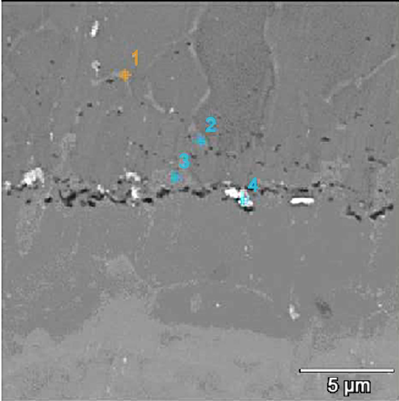
Figure 3. Microstructure of the zirconium-doped aluminide coating deposited by CVD method at 1020˚C for 2 h.
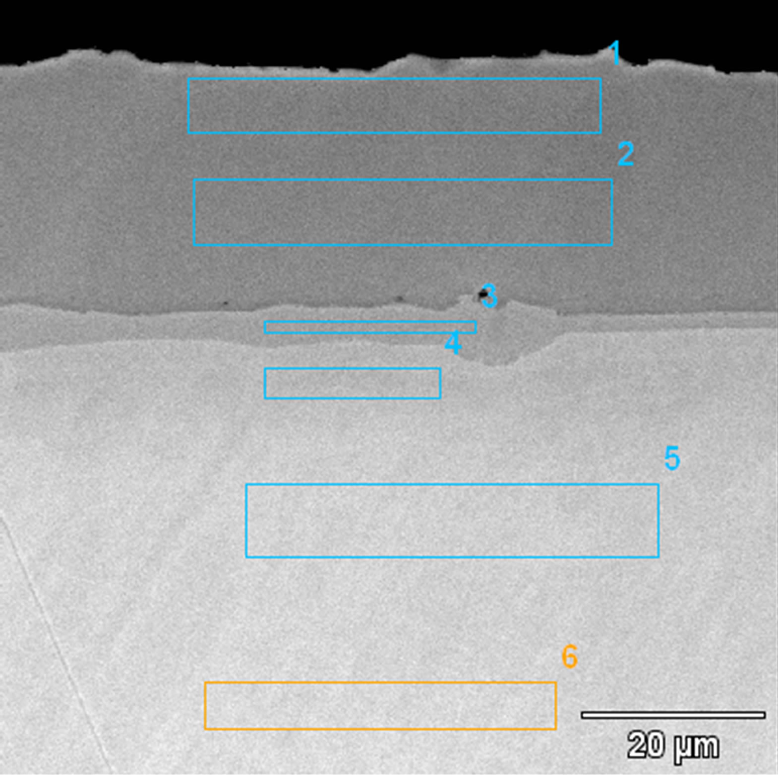
Figure 4. Microstructure of the zirconium-doped aluminide coating deposited by CVD method at 1020˚C for 5 h.
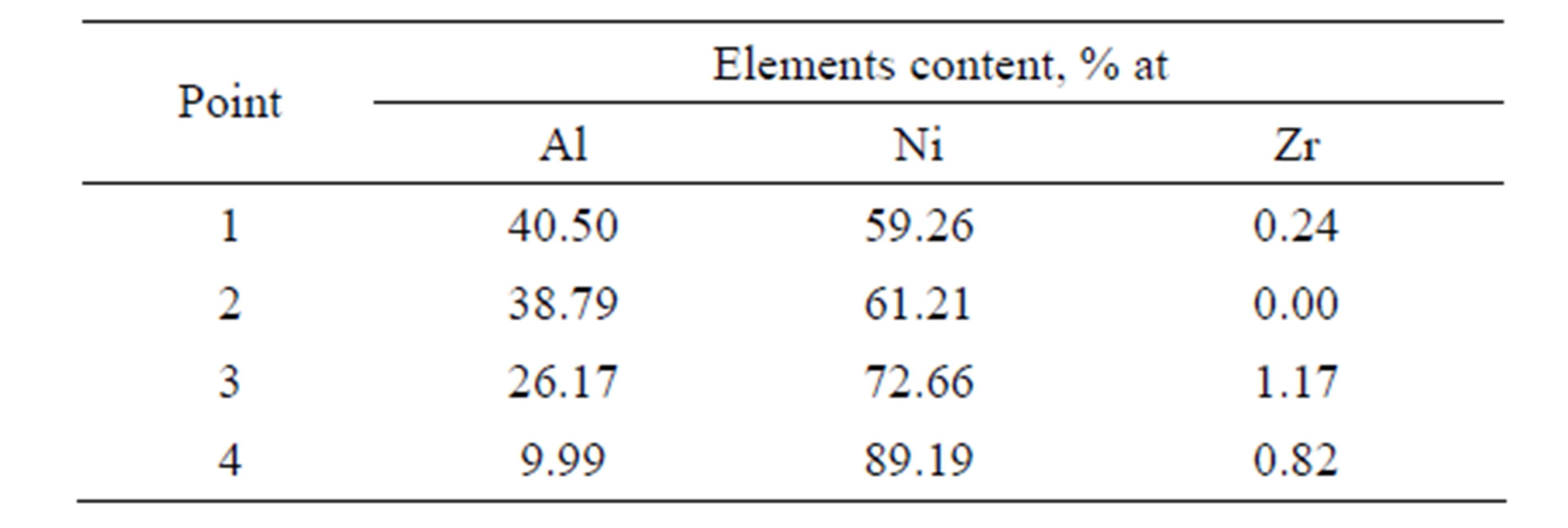
Table 1. Chemical composition on the cross-section of zirconium doped aluminide coating deposited by CVD process method at 1020˚C temperature for 2 h.
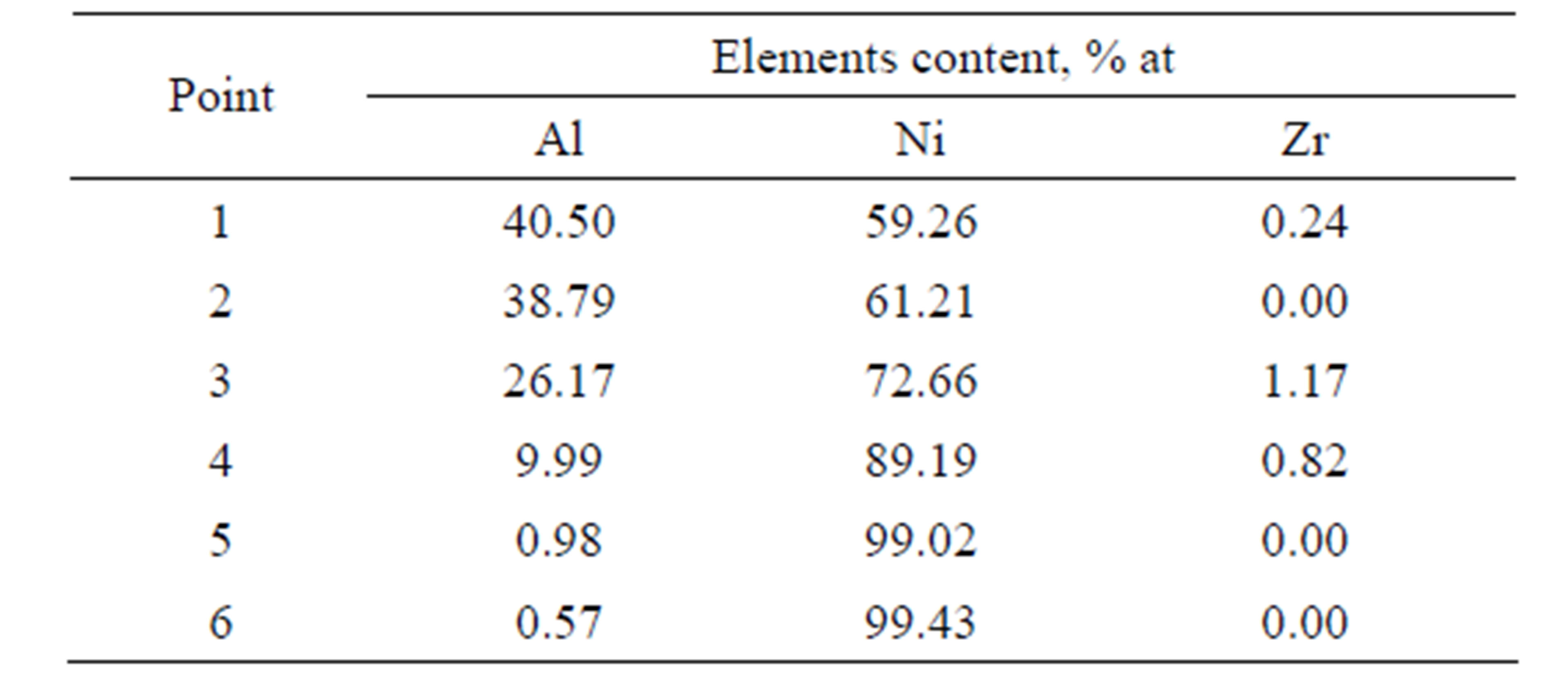
Table 2. Chemical composition on the cross-section of zirconium doped aluminide coating deposited by CVD process method at 1020˚C temperature for 5 h.
Microstructures of both coatings are similar. In both cases, it is a triple zone structure. Chemical compositions of zones, see Tables 1 and 2, correspond to β-NiAl, γ’- Ni3Al and γ-Ni(Al). The presence of these phases was confirmed by the XRD analysis [21] (Figure 5).
The elongation of the time of zirconium-aluminizing process from 2 to 5 h leads to increase of the coating thickness from 30 to 50 μm. The EDS analysis and concentration profiles of the cross-section of the coating showed the nickel outward diffusion from the substrate and the inward aluminum diffusion from the surface to the nickel substrate (Figure 6). In the coating deposited for two hours zirconium was found in “inclusions” between the β-NiAl and the γ’-Ni3Al zones (Figure 3 and Table 2). Aluminum diffused inward to the nickel substrate, whereas zirconium diffused to the β-NiAl/γ’-Ni3Al layers’ border, where Zr atoms substitute for Al atoms in the β-NiAl phase [23]. The Kirkendall porosity was observed on the border between β-NiAl and γ’-Ni3Al layers (Figure 3). The value of nickel diffusion coefficient is bigger than aluminum diffusion coefficient (DNi > DAl). The unbalanced flux of nickel and aluminum atoms results in the differences in microvolume and causes stresses in the diffusion zone. The microvolume is reduced in the area of higher nickel concentration and vacancies are formed. When the number of vacancies is high, vacancies coagulate and therefore pores are being formed. This way, the Kirkendall porosity is generated [23].
Zirconium does not form any inclusions but dissolves in the coating’s phases in the coating deposited for 5 hours (Figure 4). The Kirkendall porosity was not ob-
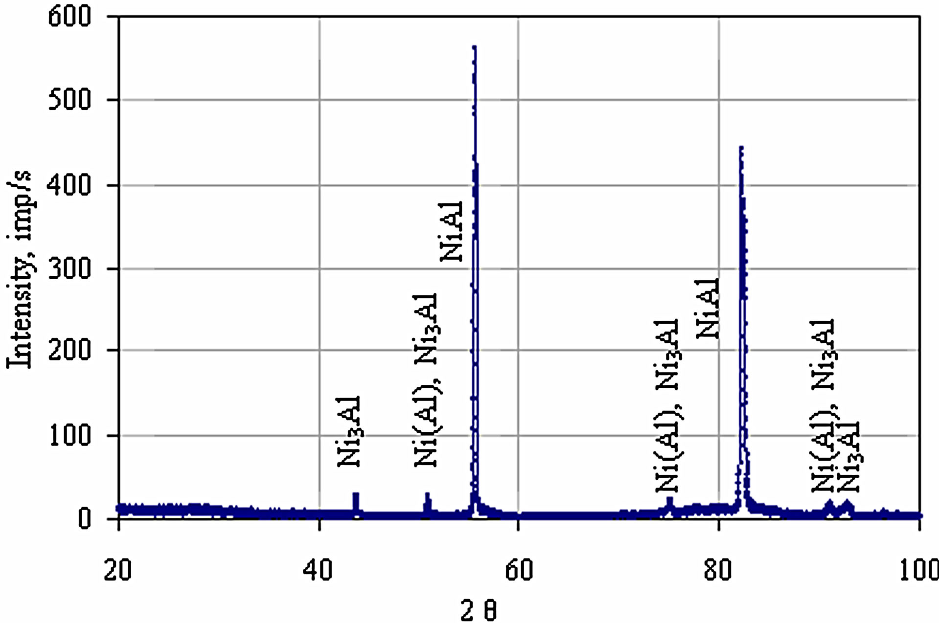
Figure 5. The XRD pattern of the zirconium-doped aluminide coating deposited by CVD method at 1020˚C for 5 hours.
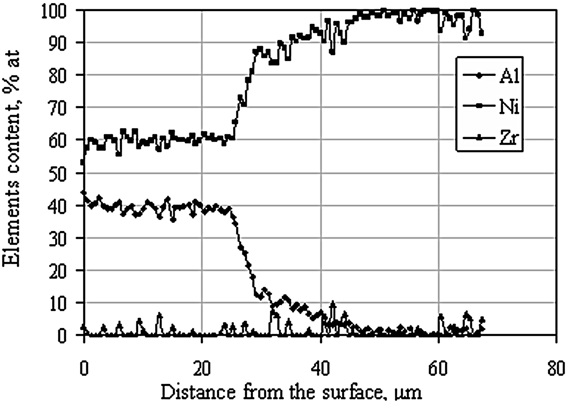
Figure 6. EDS linear analysis on the cross-section of the zirconium-doped aluminide coating deposited by CVD method at 1020˚C for 5 hours.
served. The absence of Kirkendall voids may be an evidence of balanced flow of elements forming the coating. It is worth mentioning that when the CVD process lasted for 2 hours, zirconium was situated in inclusions at the interface between β-NiAl and γ’-Ni3Al phase and Kirkendall porosity was observed. After 5 hours process, neither inclusions nor Kirkendall porosity were observed. It seems that elongation of the diffusion time balanced the diffusion flux.
The microstructure of coatings obtained after the diffusion treatment of the Zr 7 μm thick and Al 0.5 μm thick and the Zr 7 μm thick and Al 0.7 μm thick layers deposited by EB-PVD method is similar (Figures 7 and 8). The coating consists of two zones: an outer (2 - 3 μm thick) zone and an internal (13 - 12 μm thick) one. On the top of the coating the proportion of Ni, Al and Zr corresponded to γ-Ni(Al,Zr) phase (Figure 7 and Table 3 Point 1, Figure 8 and Table 4 Point 1).
The chemical composition of the inner zone distributed below the γ-Ni(Al,Zr) phase corresponds to the Ni7Zr2
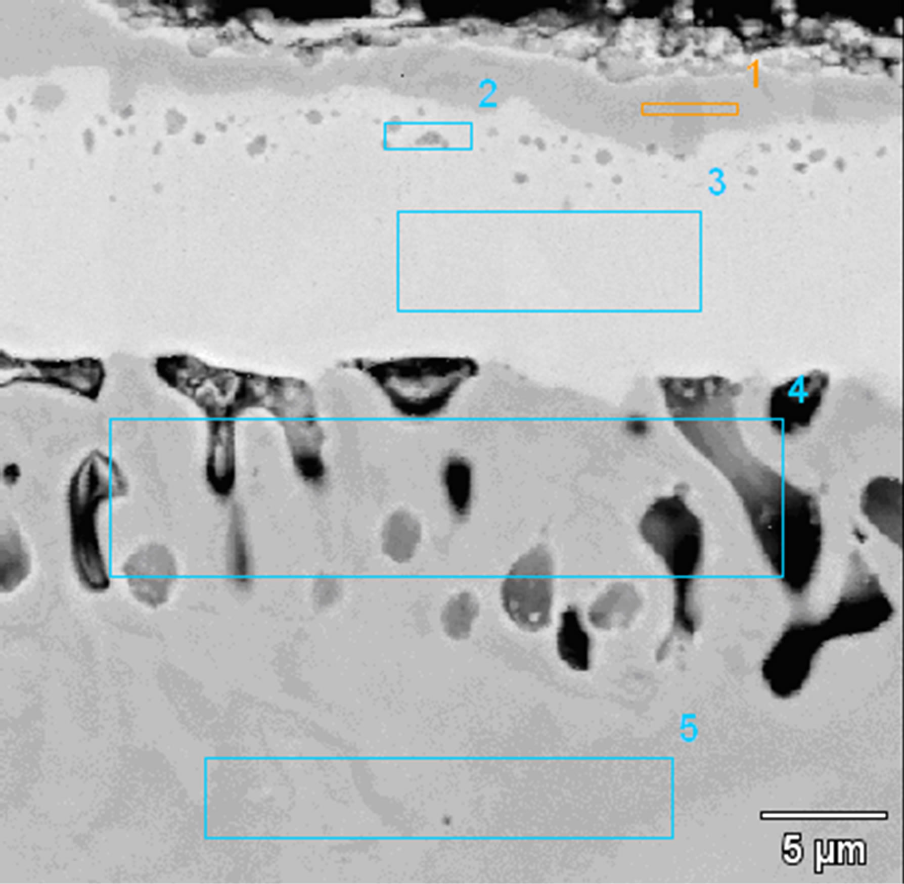
Figure 7. Microstructure of the Zr 7 μm thick and Al 0.5 μm thick coatings deposited by EB-PVD method after the diffusion treatment.
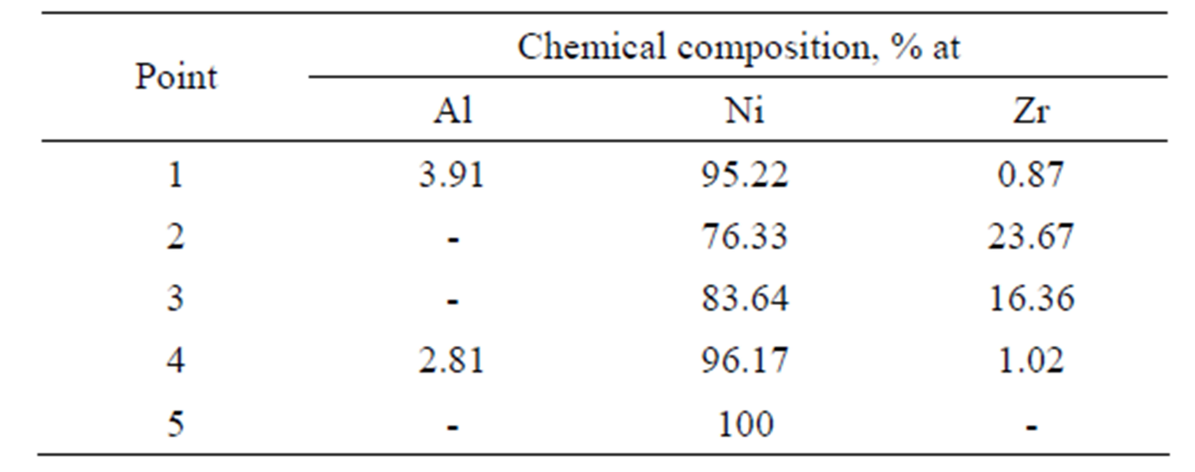
Table 3. Chemical composition on the cross-section of the Zr 7 μm thick and Al 0.5 μm thick coatings after the diffusion treatment.
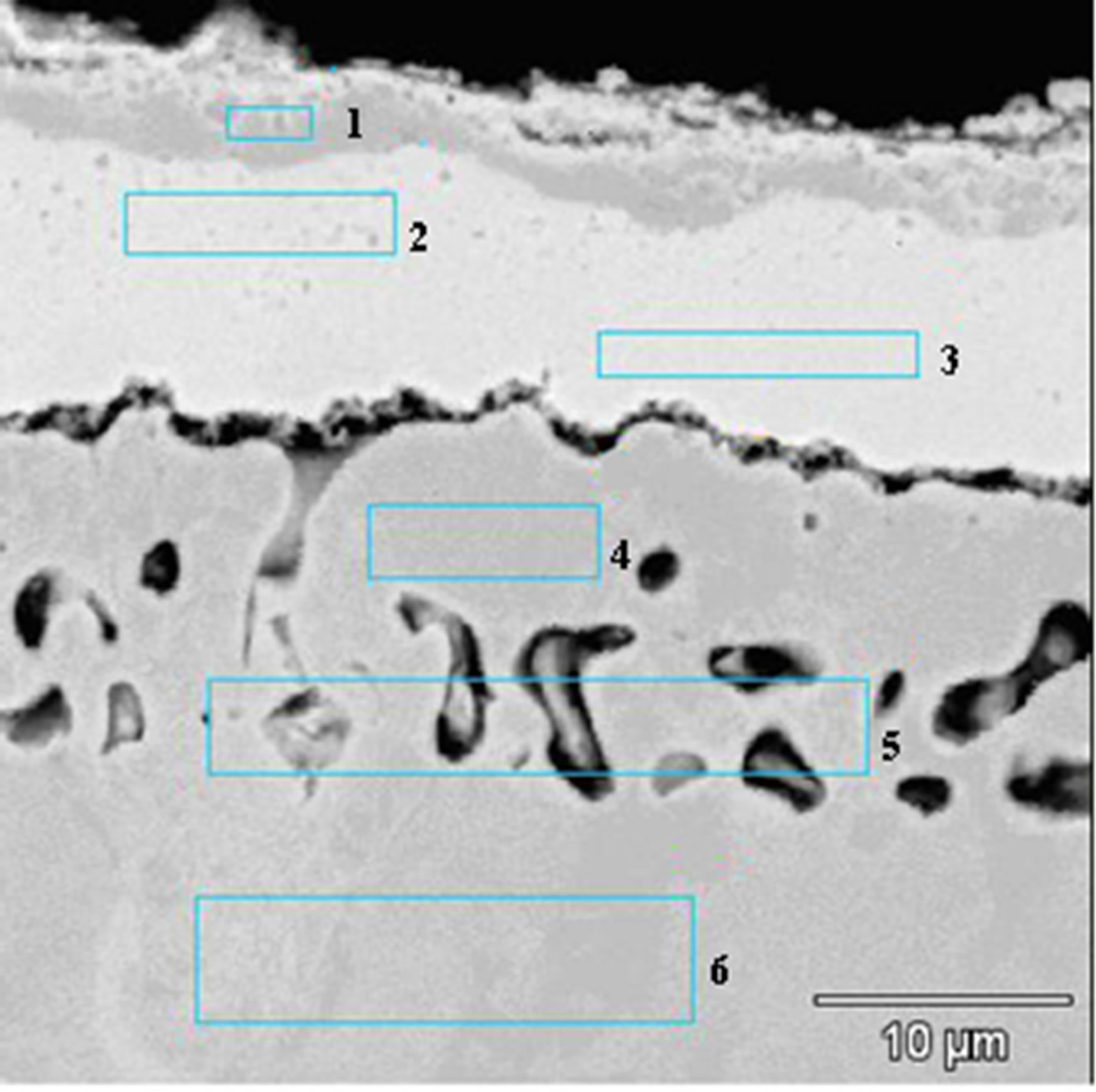
Figure 8. Microstructure of the Zr 7 μm thick and Al 0.7 μm thick coatings deposited by EB-PVD method after the diffusion treatment.
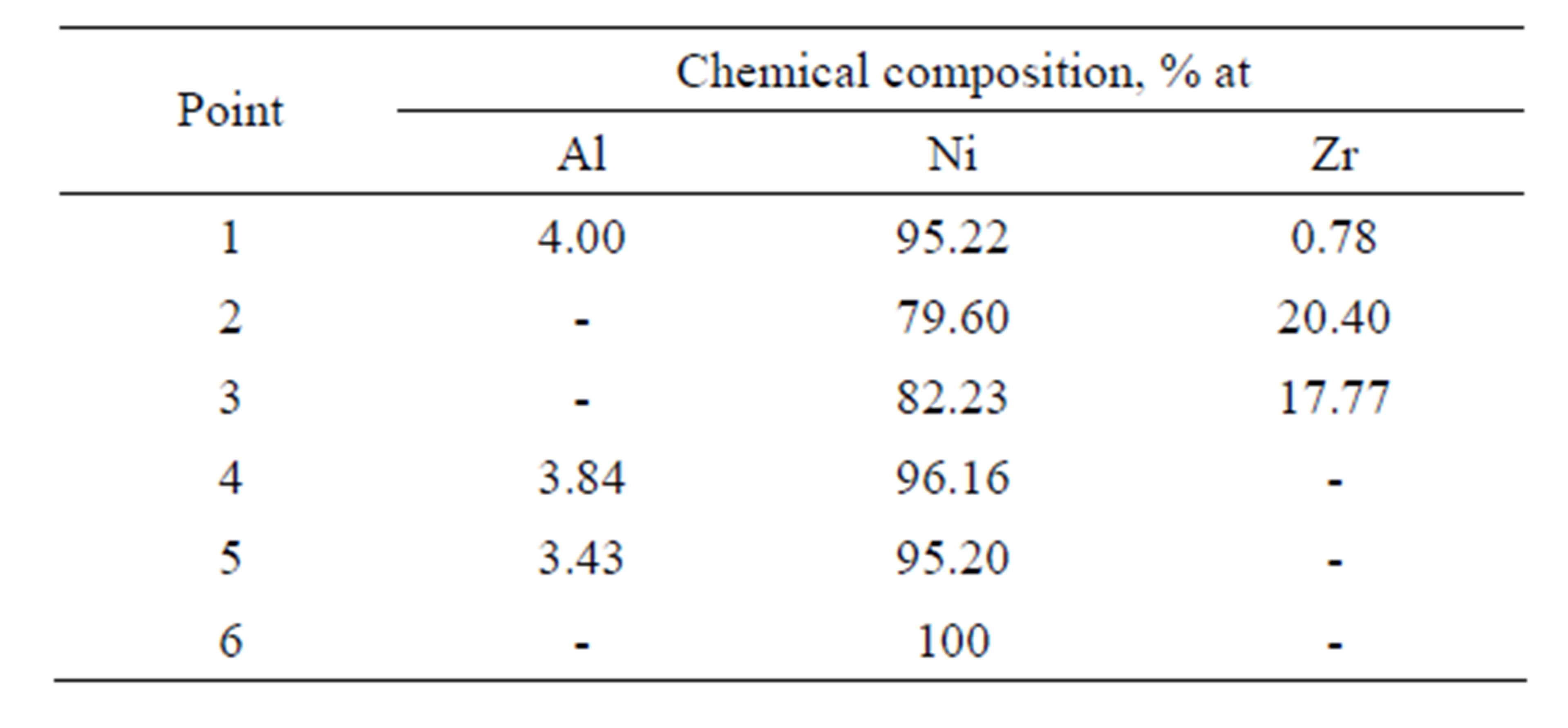
Table 4. Chemical composition on the cross-section of the Zr 7 μm thick and Al 0.7 μm thick coatings after the diffusion treatment.
phase (Figure 7 and Table 3 Point 2, Figure 8 and Table 4 Point 2) and Ni5Zr phase (Figure 7 and Table 3 Point 3, Figure 8 and Table 4 Point 3). Below the presence of the γ-Ni(Al,Zr) phase was detected (Figure 7 and Table 3 Point 4, Figure 8 and Table 4 Point 4, 5). The presence of the Ni7Zr2 and Ni5Zr phases was confirmed by the XRD analysis (Figures 9 and 10).
There are observed many voids in the substrate just above the coating. Kirkendall porosity is an evidence of an unbalanced flow of nickel, aluminum and zirconium atoms in the diffusion zone. Kirkendall voids are generated below the original interface, so the outward nickel diffusion is faster than the inward zirconium and aluminum diffusion.
The diffusion treatment of Zr layer 1 μm thick and Al layer 1 μm thick leads to formation of intermetallic phases enriched with nickel and zirconium (Figure 11. Point 2% - 84.97% at Ni, 12.95% at Zr; Point 4% - 84.27% at Ni, 15.02% at Zr) (Figure 11 and Table 5). According to Ni-Zr phase diagram, chemical composition of these phases corresponds to Ni5Zr phase (Figure 12). EDS linear analysis on the cross-section indicates that intermetallic phases are formed 5 - 7 μm below the coating’s surface (Figure 13).
After the diffusion treatment process, zirconium formed intermetallic phase Ni5Zr, whereas aluminum did not form any phases with nickel or zirconium. Its concentration is almost the same along the investigated cross section (20 μm) (Figure 13), so it may be assumed that aluminum dissolves in nickel and solid solution γ-Ni(Al) is being formed.
The differences in the hardness of the coatings deposited by CVD and EB-PVD methods (Table 6) were found. The biggest hardness is in the internal zone of coatings. The increase of hardness values in the internal zone of coatings is due to the intermetallic phase formation.
4. Conclusions
The coatings’ microstructure is influenced by several factors such as the deposition method, the diffusion time and the amount of zirconium. Molar volumes of diffusing
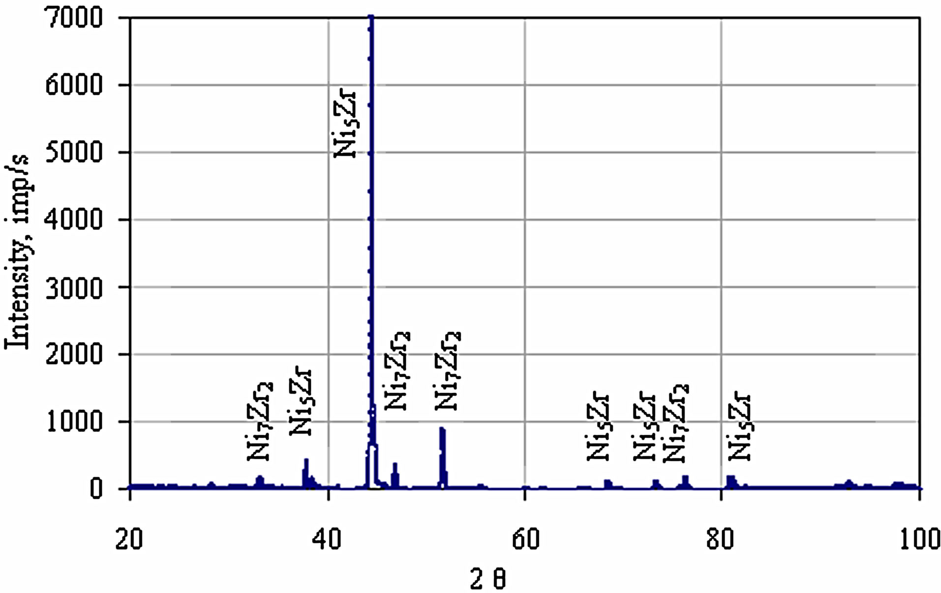
Figure 9. The XRD pattern of the Zr 7 μm thick and Al 0.5 μm thick coatings after the diffusion treatment.
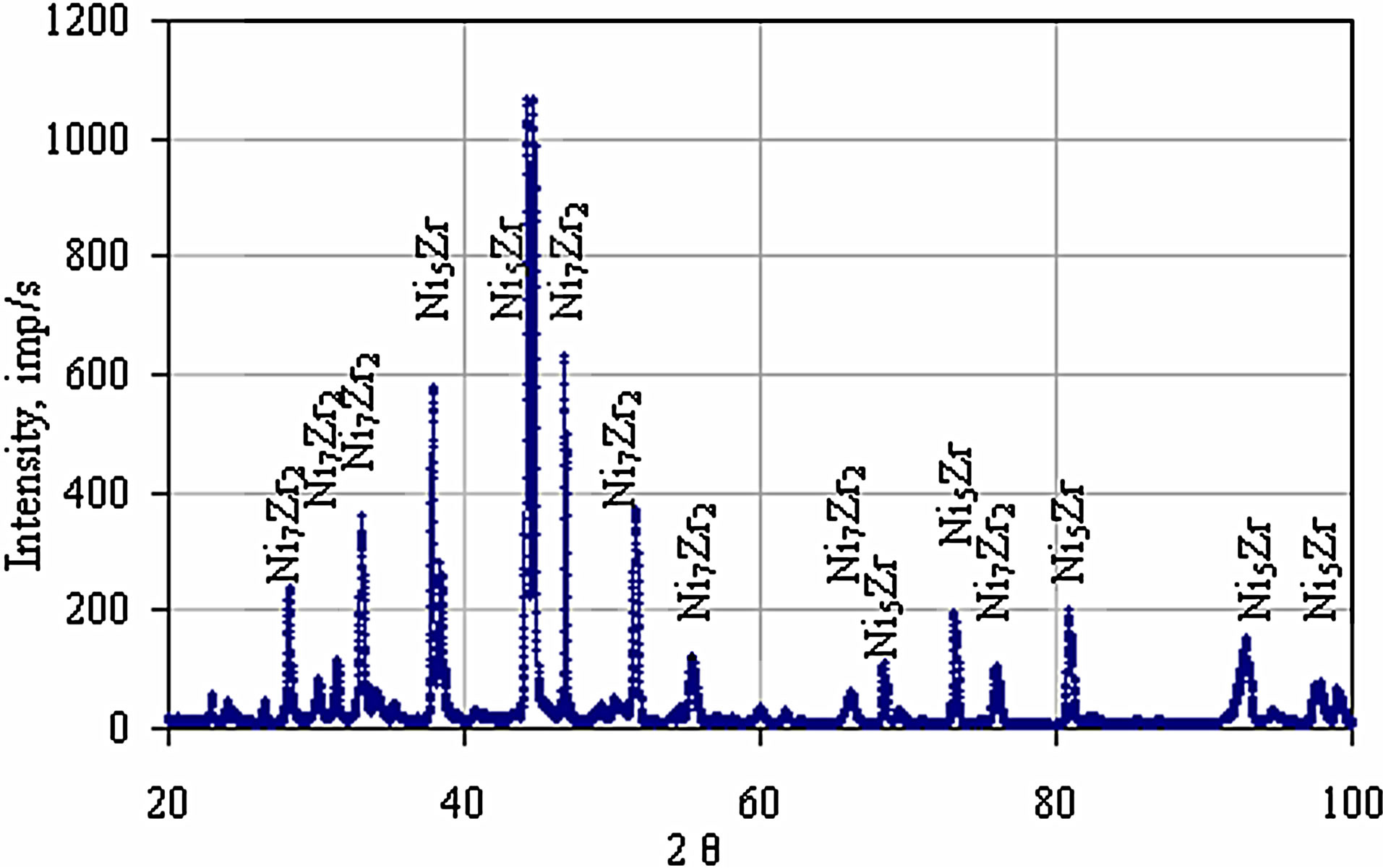
Figure 10. The XRD pattern of the Zr 7 μm thick and Al 0.7 μm thick coatings after the diffusion treatment.
elements are different (vNi = 6.59 × 10⁻⁶, vAl = 10.6 × 10⁻⁶, vZr = 14.02 × 10⁻⁶ m3/mol), which may cause the unbalanced flux of elements. When the diffusion time is long and the zirconium amount is small (as for the 5 hours CVD process), nickel, aluminum and zirconium fluxes are balanced, and there are no voids or intermetallic inclusions and zirconium dissolves in the coating (see Figures 4-6). When the diffusion time is shorter (2 hours, CVD process), the coatings thickness is smaller, zirconnium is found in NiAl(Zr) inclusions between the β-NiAl and the γ’-Ni3Al zones and the Kirkendall porosity is observed on the border between β-NiAl and γ’-Ni3Al layers’ (Figure 3), [21]. It is an evidence of the unbalanced nickel and zirconium flux. Hardness of NiAl and Ni3Al zones is about 446 - 498 HV.
In coatings obtained by the diffusion treatment of Zr 1 µm thick and Al 1 µm thick layers deposited by the EB-PVD method, inclusions of the Ni5Zr phase (hardness about 647 HV) were found at a certain distance from the sample’s surface, but no porosity was observed. Aluminum does not form any intermetallic phases with nickel but dissolves in the nickel substrate (Figures 12 and 13). The increase of the zirconium layer thickness to 7 µm resulted in unbalanced zirconium and nickel fluxes.
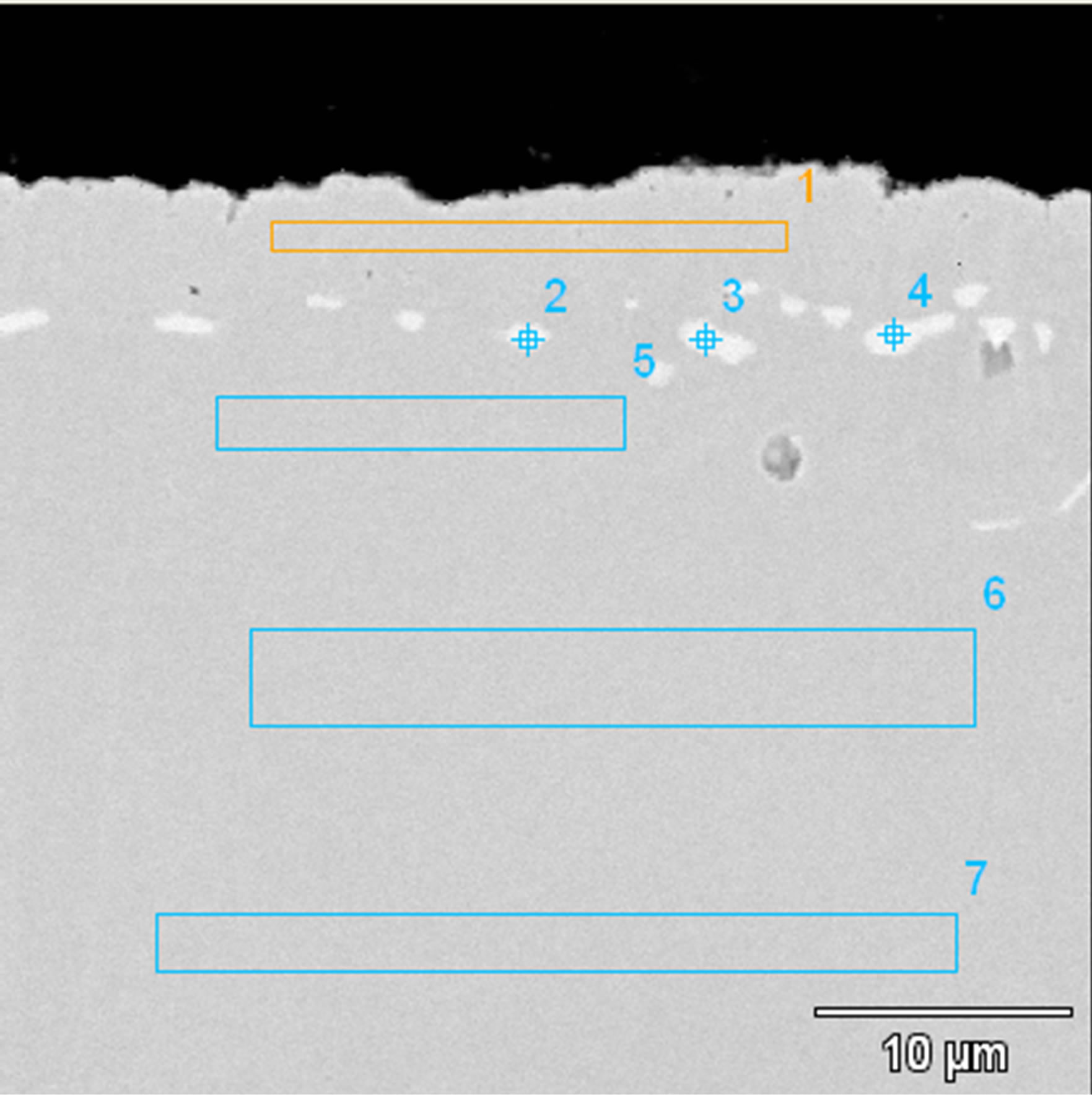
Figure 11. Microstructure of the Zr 1 μm thick and Al 1 μm thick coating deposited by EB-PVD method after the diffusion treatment.
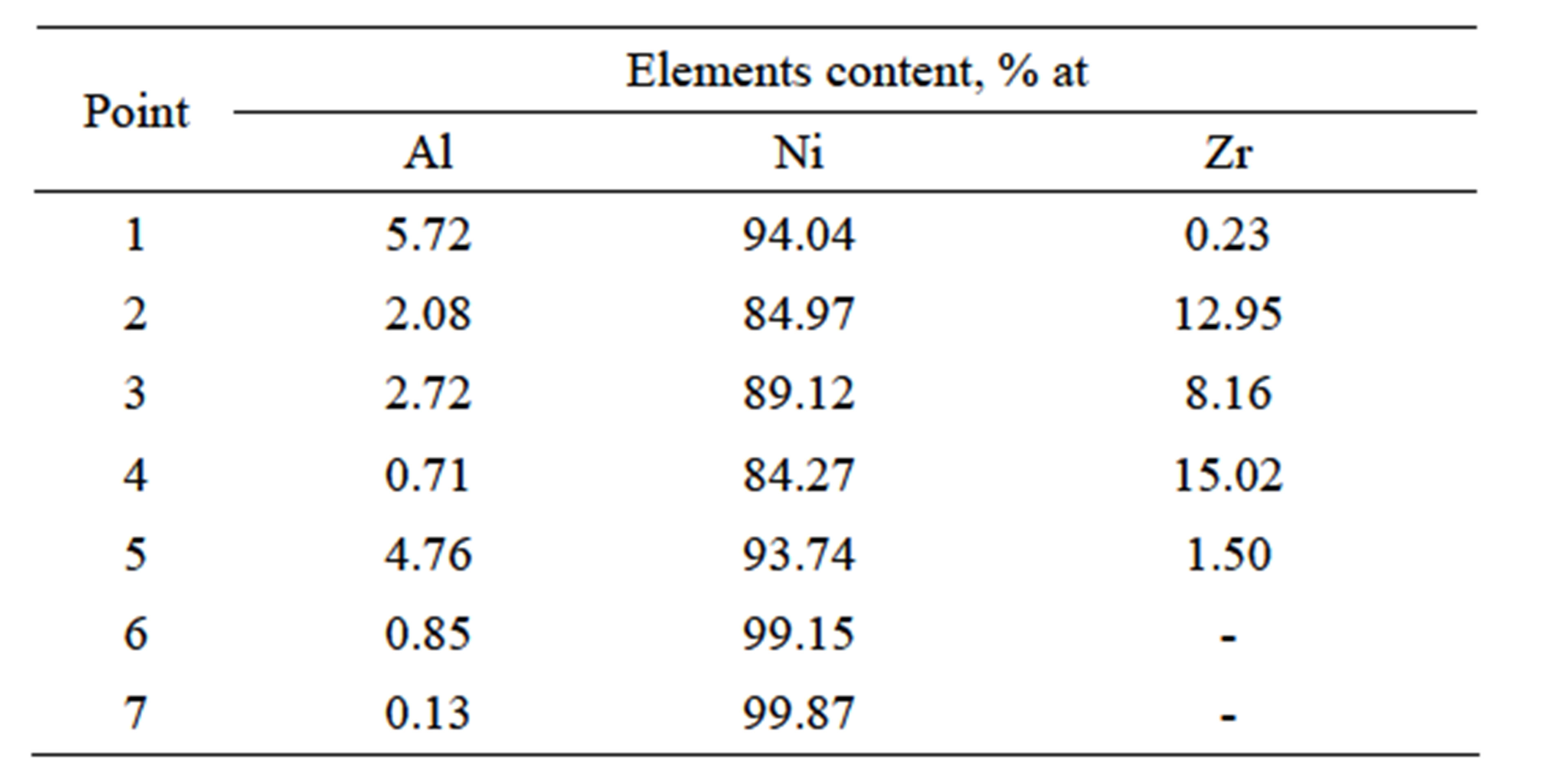
Table 5. Chemical composition on the cross-section of the Zr 1 μm thick and Al 1 μm thick coating after the diffusion treatment.
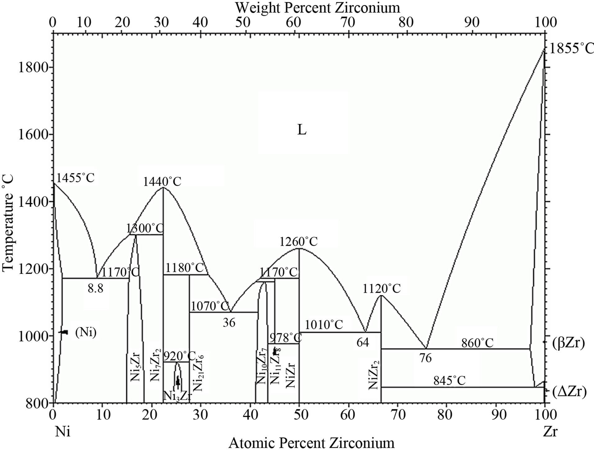
Figure 12. The Ni-Zr phase diagram [24].
There are many voids in the substrate just below the substrate surface (Figures 7 and 8) and inclusions of Ni7Zr2
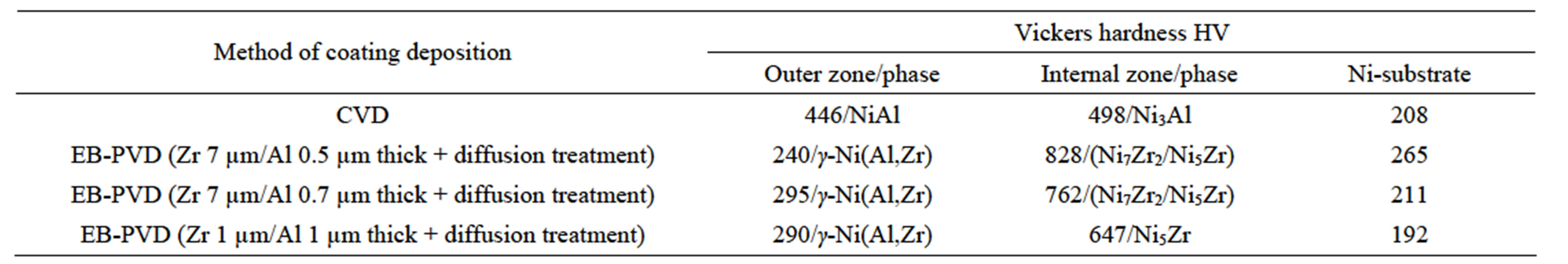
Table 6. Vickers hardness distribution on the cross-section of the zirconium-aluminide coatings deposited by the CVD and EB-PVD methods.
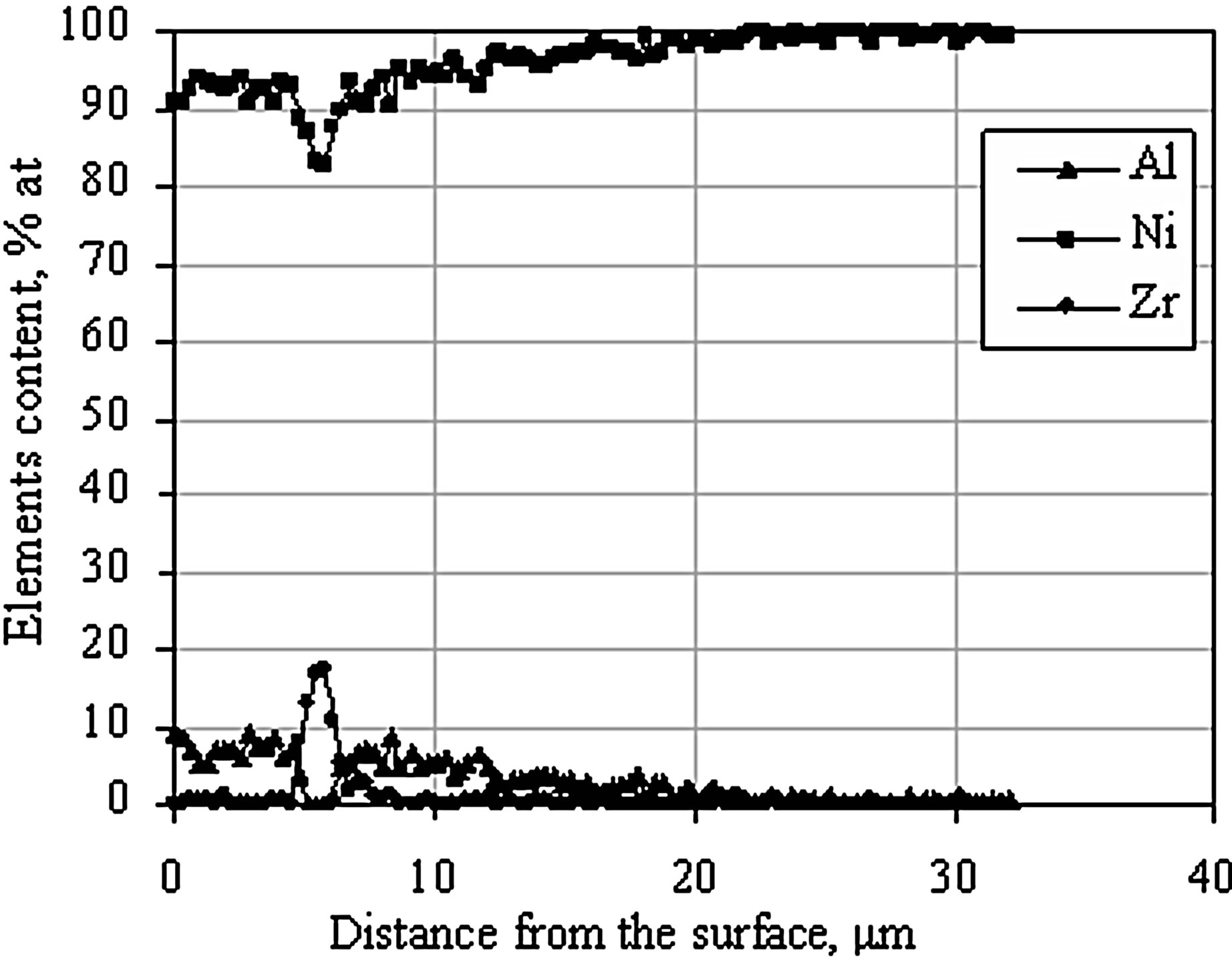
Figure 13. EDS linear analysis on the cross-section of the Zr 1 μm thick and Al 1 μm thick coating after the diffusion treatment.
and Ni5Zr intermetallic phases are formed below the coating’s surface Figures 7-10). The hardness of these phases is about 762 - 828 HV.
5. Acknowledgements
The presented research was supported by the National Science Centre, Poland, project number 2011/01/DST8/ 05/036.