Model of Multi-Source Nanonetworks for the Detection of BRCA1 DNA Alterations Based on LSPR Phenomenon ()
1. Introduction
In the past few decades, nanotechnology has emerged as a novel evolution of technology enabling the design of miniaturized devices at nanoscale level (i.e., nanorobots and nanoparticles). At this scale, the behaviors and characteristics of nanodevices need more comprehension and a deep knowledge with respect to well-known features of devices at the macroscale level [1]. Indeed, a nanodevice is the most basic functional unit, which is allowed to perform very easy tasks, like sensing or actuation, due to the passive nature of these devices. The design and fabrication of nanosensors are difficult tasks for researchers, since a nanosensor is not just a device with reduced size, but has unique properties of nanomaterials and nanoparticles. For instance, nanosensors can detect chemical compounds in concentrations, or the presence of different infectious agents, such as virus or bacteria [2,3]. As an example, in [2] the authors use a Quantum Dots-DNA (QDs-DNA) nanosensor based on Fluorescence Resonance Energy Transfer (FRET) for the detection of the target DNA and single mismatch in Hepatitis B Virus (HBV) gene.
Nanoparticles can be designed accordingly to prolong circulation, enhance drug localization [4], increase drug efficacy, and potentially decrease chances of multidrug resistance. Recently, research in the field of cancer diagnostic has made remarkable advances, through the use of nanotechnology for the development of nanoparticles. Basically, gold nanoparticles and NearInfraRed (NIR)-emitting semiconductor QDs are the most widely used. In [5], plasmonic nanoparticles are investigated for sensing applications, while in [6] they are used in several experiments on small animals for in-vivo detection of cancer cells. On the other side, QDs are high fluorescent nanocrystals that can be modified to meet the needs of tumor-selective probes for diagnostic tumor imaging applications, although biocompatibity and toxicity issues can occur [7-9]. In [9], the authors investigate fluorescent imaging with QDs both in vitro and in vivo, and potential barriers to their use in practical biomedical applications.
New materials are becoming available for nanoscale design and fabrication of nanodevices. Several physical, chemical and biological nanosensors have been developed by using novel nanomaterials, such as crystal materials. Gallium, phosphate, quartz, and ceramic are chosen for their durability and piezoelectric properties of developing and retaining an electric potential (charge), when subjected to mechanical stress. Graphene and its derivatives, namely Graphene NanoRibbons (GNRs) and Carbon NanoTubes (CNT), are used for the design of nanoantennas [10-12].
Several projects consider the use of nanodevices for medical applications as diagnosis and drug delivery. Among them we cite 1) NAD (Nanoparticles for Therapy and Diagnosis of Alzheimer Disease) whose aim is to utilize nanoparticles specifically engineered for the combined diagnosis and therapy (theranostics) of Alzheimer’s disease [13], 2) NANO3T (Biofunctionalized Metal and Magnetic Nanoparticles for Targeted Tumor Therapy) a multi-disciplinary project to develop and explore the use of magnetic nanoparticles as agents for tumor hyperthermia [14], and 3) PANOPTES (Peptidebased Nanoparticles as Ocular Drug Delivery Vehicles) that develops methodology for the manufacture of novel peptide-based nanoparticles for drug delivery [15]. Finally, GRANET project (Graphene-enabled Nanonetworks in the Terahertz Band) investigates the radiation characteristics of planar nano-antennas based on GNRs and larger graphene sheets.
A set of nanodevices, sharing the same medium (e.g., the biological tissue or the bloody flow) and collaborating for the same task, forms a nanonetwork [16]. Nanonetworks are expected to expand the capabilities of single nanodevices and enable new nanotechnology applications in biomedical, environmental, military, industrial and consumer fields.
Communication and signal transmission techniques occurring in nanonetworks are challenging topics, due to the particular environment (i.e., the human body and biological tissues) and to the limited computation skill of nanodevices. Molecular Communication (MC) represents a promising communication paradigm for nanonetworks [16], where molecules (i.e., nanoscale particles) are transmitted by nanomachines, propagate in the medium following a diffusion process, and then arrive at the receiver where a ligand-receptor binding occurs. More in detail, three architectures for nanonetworks are known [17], where for each case nanoparticles can propagate using 1) carrier substances, 2) predictable, and 3) unpredictable (spontaneous) diffusion process i.e., nanoparticles are (are not) subjected to the laws of diffusion in a fluidic medium. The last case where nanoparticles show a behavior totally spontaneous (i.e., a priori unknown) can result as the most challenging.
Recently, the modeling of diffusion-based nanoparticles communications has been investigated in [17] for a point-to-point communication model, where one transmitter emits nanoparticles towards a receiver. The emission, diffusion and reception processes have been described through an analytical model. As a result, this scenario represents the pillar for the theory of the molecular communications, due to the intuitive approach with one transmitter and one receiver.
However, in real scenarios (e.g., for extra-vivo sensing applications), the emission, diffusion and reception processes can show different behaviours. For example, many biomedical applications require a multi-source emission of nanoparticles, where each source (i.e., nanomachine) can emit a particular type of nanoparticles (i.e., with a given shape and size). As a consequence, synchronous and asynchronous nanoparticle emission can affect the diffusion process and degrade network performance (i.e., with an increase of interference and nanoparticles’ collisions). The same consideration exists at the receiver side, where a selective reception of nanoparticles occurs (i.e., a given nanoparticle can form a complex only with the “corresponding” receptor).
Other authors have investigated novel schemes of molecular communications, starting from classical concepts of the information theory and adapting into nanonetworks [18,19]. In [19], the authors present the MARCO scheme, where the emission process occurs for different kinds of nanoparticles in asynchronous manner, so that information is encoded by means of arrays of nanoparticles.
Once the nanoparticles arrive at the receiver, they are bound and the detection process can occur. Electromagnetic fields and heat are largely used for sensing applications. For example, magnetic nanoparticles can be used to selectively damage or kill cancer cells by heating them, since intracellular hyperthermia has the potential to achieve localized tumor heating without any side effects [20]. Furthermore, by functionalizing the nanoparticles with biological agents such as antibodies or single stranded DNA chains, nanoparticles are forced to bind preferably to specific target cells. This aspect is the focus of our extra-vivo sensing application, that is, the multidetection of DNA alteration of the BReast CAncer susceptibility gene 1 (BRCA1).
BRCA1 and BRCA2 are human genes belonging to a class of genes known as tumor suppressors. Mutation of these genes has been linked to hereditary breast and ovarian cancer. For the BRCA1, this gene causes a genetic susceptibility to breast cancer and changes in its alternative splicing profile have been associated with malignant transformation [21,22]. A woman’s risk of developing breast and/or ovarian cancer is greatly increased if she inherits a harmful BRCA1/BRCA2 mutation.
Genetic tests are available to check for gene mutations. However, due to the vast number of alternative splice variants, tissue and cell type specific pattern of the relative expression levels of these variants, it is difficult to use alternative splicing profiling as a diagnostic tool for breast cancer.
Techniques based on the use of metallic nanoparticles illuminated by an impinging electromagnetic wave (visible and near infrared region) are largely exploited, as alternative approaches for gene alterations detection. The resonant frequency related to the collective electron motion has a strongly dependence on the shape, size, composition of the nanoparticles, as well as on the dielectric properties of the background environment. This technique is known as Localized Surface Plasmon Resonance (LSPR). In this paper, we apply the LSPR phenomenon for the detection of BRCA DNA alteration, when biological gold nanoparticles are captured at the receiver.
The remainder of this paper is organized as follows. In Section 2, we discuss the physical end-to-end model for flows of nanoparticles sent by a transmitter toward a receiver. How nanoparticles are emitted, diffused and received is the objective of this paper. Particularly, we first address the emission process for a multinanomachine source scenario in synchronous and asynchronous mode. Then, we present the diffusion and reception processes. Once the nanoparticles are captured by the receiver, the detection of BRCA DNA alterations occurs. The sensing platform is then illustrated in Section 3, while simulation results are described in Section 4. Finally, conclusions are drawn at the end of the paper.
2. The Physical End-to-End Model for Nanoparticles
In this section, we will present the physical model of the emission, diffusion and reception of nanoparticles. We will investigate how nanoparticles (1) are transmitted from a set of three nanomachines, (2) diffuse along the gap that separates the transmitter from the receiver, and then (3) arrive at the receiver. All the processes are assumed taking place inside the space , which contains a fluidic medium, initially filled with a homogeneous concentration of particles equal to zero.
In our model, we consider that a single nanoparticle is an indivisible object, which is released to (during the emission process), or collected from (during the reception process), a position in the space , by means of chemical reactions. Moreover, when a nanoparticle is not emitted or received, it is subjected to the diffusion process and moves into the space following the laws of diffusion of particles in a flow. The space is assumed as having infinite extent in any direction, and nanoparticle are free to move everywhere in the space, following a Random Mobility Model (RMM).
Nanoparticles are emitted by three nanomachines (sources), each of them transmitting nanoparticles of different shape ( , cylinder, cube and rod) and same material (i.e., gold). The nanomachines have an independent behavior, such as the
  -th nanomachine can emit a given flow of nanoparticles in the time instant
 , with
 . For sensing applications, we assume that the nanomachines can emit nanoparticles both in synchronous (i.e., with
 ), and asynchronous (i.e.,
 ) mode.
A group of nanomachines forms what we define transmitter i.e., an entity emitting different kinds of nanoparticles at different rates and for positive concentrations. We assume the transmitter is placed in the space  in the position along
  axis (i.e., at
  [nm]); the nanoparticles diffuse in the space and reach the receiver laying in the position
 , with
  [nm]. In our model, the receiver is comprised of a set of unit cells, each of them has three square gold patches (receptors) deposited on a silica substrate, and functionalized for the capture of target BRCA
 DNA sequences i.e., Target Sequences. Each patch is functionalized with the structure of the BRCA
 splice with the corresponding sandwich assays. The chemical receptors are BRCA
 alternative splice variants i.e.,
  ,
,  , and
, and  [23]. They are accordingly functionalized for the capture of one type of nanoparticle (i.e., circular, cylinder and square receptors can capture only rod, cylinder and cube nanoparticles, respectively). As a consequence, the probability of capturing a nanoparticle (i.e., the probability of forming a complex) is equal to
  for each type of nanoparticle, considering that each patch is functionalized with a Capture Sequence. Moreover, for sensing purpose, we assume that each nanoparticle can be only captured by the receptor, and not released; the release process is not investigated in this paper.
The physical end-to-end model can be well explained through the scheme in Figure 1, where we have highlighted the main modules of emission, diffusion and reception of nanoparticles. Notice that each process is trigged by an input signal: an initial signal  modulates the particle concentration rate at the transmitter side
 ; this is then propagated by the diffusion process to the receiver side, which finally detects the concentration signal
  and then generates the received signal
 .
.
Each module is represented as a black box (i.e.,  ,
,  , and
, and ). Our aim is the modeling of the delay that occurs in 1) the transmitter module i.e.,
  [s] the time necessary to transmit a flow of nanoparticles, 2) the diffusion process i.e.,
  [s] the time for a nanoparticle to move along the gap from
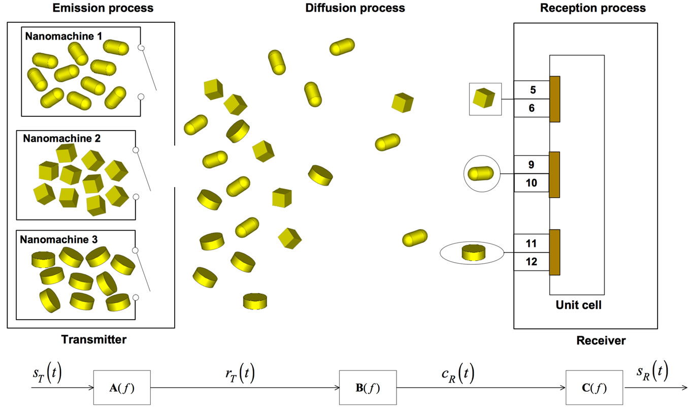
Figure 1. End-to-end physical model of the nanonetwork scenario, comprised of one transmitter and one receiver. In the emission process, the transmitter is comprised of 3 nanomachines, allowed to emit nanoparticles (a)synchronously. The diffusion process is ruled according to Fick’s first law. In the reception process, nanoparticles are captured in “selective” mode. At the receiver side, we show the unit cell comprised of three gold patches. In each patch, numbers denote different exons, as appear in [24] (they are not drawn to scale).
the transmitter to the receiver, and 3) at the receiver i.e.,  [s] the time necessary to receive the nanoparticles. Equations (9), (34) and (39) will be introduced to describe the delay in the transmission, diffusion and reception process, respectively.
2.1. Multi-Nanomachine Emission Process
The emission process aims to modulate the particle concentration rate at the transmitter. This is comprised of three nanomachines, each of them is modeled as a box containing a nanoparticle concentration value , with
 , and provided with an aperture from where the nanoparticles can exit, when emitted.
Each nanomachine receives the same input signal , which represents the input of the end-to-end model. The particle flux is defined as the net particle concentration leaving/entering the transmitter per unit time. The particle concentration at the output of the
  -th nanomachine
 , with
 , is the average concentration in the proximity of the
  -th nanomachine, assumed equal to zero initially. This variation in the particle concentration at the output of the transmitter is expressed as:
 (1)
(1)
where we assumed the superposition principle occurs.
The particle concentration flux emitted by the  -th nanomachine is stimulated by a concentration gradient between
  and
and . Basically, the particle concentration inside each nanomachine is trigged according to the input signal
 : for increases (decreases) of
 , the transmitter increments (reduces) each
 , and then the
  -th particle concentration at the output
  is increased (decreased) too; as a result, the expression in (1) increases (decreases), as well. It is worth noticing that a negative rate modulation can occur when
 , and then
  is negative. However, this case is not assumed in our model i.e., the nanomachines emit flows of nanoparticles.
This behavior can be well depicted through an electrical parallel RC circuit, as that one shown in Figure 2(a). We consider the  -th nanomachine as the parallel group of the resistance
  and capacitor
 , with
 . The
. The  -th switch is closed when the
  -the nanomachine is emitting nanoparticles, otherwise it is open. Multi-transmissions are allowed in synchronous and asynchronous mode. In the case of
  nanomachines transmitting at the same time instant, the circuit of Figure 2(a) becomes as in Figure 2(b), where the input current
  represents the input signal
  of the end-to-end model of Figure 1, while the output current
  represents the output signal
 .
.
The resistor  and the capacitor
  are obtained as follows:
 (2)
(2)
From the electrical circuit theory, we compute the Time Fast Fourier Transform (TFFT) of the equivalent

Figure 2. (a) Multi-nanomachine emission process circuit model, where each RC group represents a transmitting nanomachine, and (b) equivalent circuit model.
RC circuit of Figure 2(b), that is
 (3)
(3)
where  and
and  are the Fourier transforms of the input and output voltage, respectively.
Notice that the nanoparticle concentration rate  can be identified with the particle concentration flux
  at the output of the transmitter i.e., for
 . The particle concentration flux
  is dependent on the particle concentration gradient at time
  and position
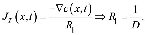
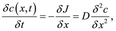
  through the Fick’s first law, as follows
 (4)
(4)
where  [cm2/s] is the diffusion coefficient, assumed as a constant value for a given fluidic medium. The diffusion coefficient depends on size and shape of nanoparticles, as well as the interaction with the solvent and viscosity of solvent. In (4), the nanoparticle concentration flux
  can be related to the output current
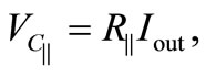
 , flowing along the resistor of the circuit in Figure 2(b), while the particle concentration gradient corresponds to the voltage along the capacitor
 , such as:
 (5)
(5)
From the circuit theory, we have
 (6)
(6)
and then it follows
 (7)
(7)
This shows that the diffusion coefficient  takes into account the contributions of three nanoparticle flows. Now, we can consider the TFFT
  of the transmitter module be equivalent to (3), that is the TFFT
  of the RC circuit in Figure 2(b)
 (8)
(8)
from which we can evaluate the delay  for the transmitter module, as:
 (9)
(9)
where  is the phase of the TFFT of
 , whose expression is easily computed as
 (10)
(10)
2.2. Nanoparticle Diffusion Process
The diffusion process of nanoparticles in the space  is strictly related to 1) the concentration rate
 , that is the output from the emission process, and 2) the way the particle diffuse in a medium i.e., in our case it is a fluid medium.
In the proposed model, we assume gold particles with different geometries that are similar to each other in terms of volume occupancy. This assumption makes easier the analysis of the diffusion process. It is well known that diffusion is always along a chemical potential gradient and stops when chemical potentials are constant along the space [24]. Typically, the chemical potential increases when concentration increases too and, for this reason, it is a fair assumption to express the diffusion in terms of concentration.
In order to understand how nanoparticles move in a three-dimensional space (lattice), we consider , and
, and , as the concentration and the chemical potential at position
  in the space
 , respectively. Then, in position
 , where
  represents a space deviation, that is the step, we have:
 (11)
(11)
Let  [kJ/mol] be the activation barrier i.e., the minimum energy required to start a chemical reaction; this also means that for a chemical reaction to proceed at a reasonable rate, there should exist an appreciable number of molecules with energy equal to or greater than the activation barrier. Then, we can define the forward rate as
 (12)
(12)
where  is the universal gas constant,
  is a constant, and
  is the temperature. We assume that in our system there is no meaningful change in terms of temperature; in fact, as a specific case, we can consider an extra-vivo application (e.g., a hair sample), and then such assumption is plausible. Moreover, (12) is usually true with the assumption that
 , where the free energy change is small within short distances. This allows writing the following:
 (13)
(13)
and also
 (14)
(14)
Let us introduce  as the vibrational frequency. Then, a nanoparticle will have enough energy per second to overcome the activation barrier
  times. In practice, we can define
  as the number of jumps of step
  per second, such as:
 (15)
(15)
Since we are considering a three-dimensional space, modeled as a lattice, the nanoparticles are free to move along six equivalent directions of vectors ,
,  , and
, and  (i.e.,
  ,
,  , and
, and , respectively). This means that the number of jumps along the
  -th direction in the time unit [s] is
 (16)
(16)
where . We can now calculate
  as the net forward rate along the direction
 :
:
 (17)
(17)
where .
.
Let us consider the nanoparticles move along the direction of . Considering
  as the number of nanoparticles per unit area in position
 , we can compute the number of nanoparticles passing through the unit area in the unit time along
  as:
as:
 (18)
(18)
Since , (18) can be written as:
 (19)
(19)
Now, let us consider the expression of chemical potential  as
as
 (20)
(20)
where  is the activity of the particle in position
 , and
, and  is a constant, named activity coefficient. Then, the derivative of (20) is:
 (21)
(21)
and by substituting (21) into (19), we will have:
 (22)
(22)
and given the similarity between (4) and (22), we can calculate the intrinsic diffusion coefficient  [cm
[cm /s] as:
 (23)
(23)
By considering the diffusion process in a threedimensional space, where a nanoparticle can move following a Random Mobility Model, along six equivalent directions, we obtain:
 (24)
(24)
from which we can recompute (15) as:
 (25)
(25)
Unfortunately, the Fick's first law works when applied to steady state systems, that is the concentration will keep constant in the time and along the space. In the specific application we are considering, the concentration can change in the time, since our nanoparticle diffuse along the space by determining different levels of concentration. For this reason, we need to consider the Fick’s second law.
Let us define  and
and  as, respectively, the local concentration and the diffusion flux through an unit area
  in position
 . Then we can write:
 (26)
(26)
and
 (27)
(27)
from which it follows:
 (28)
(28)
and by substituting  with
with , (28) is equivalent to
 (29)
(29)
Thus, from the first Fick’s law, we can obtain:
 (30)
(30)
and for a three-dimensional space we can rewrite (30) as:
 (31)
(31)
It is worth to notice that at the equilibrium state (i.e., when the concentration does not change), we obtain the first Fick’s law, that can be considered as a specific case of the second law, when applied to a steady state. However, as outlined in [17] and [25], the second Fick's law is in contradiction with the theory of special relativity. In practice, the second Fick’s law states for an instantaneous propagation of particles information, that is equivalent to allow a super-luminal information propagation speed. The Telegraph Equation [26] is commonly used to fix this problem, by considering an additional term  that represents the incoming concentration rate:
 (32)
(32)
where the term  is the relaxation time and is related with the heat diffusion process. In fact, the Telegraph Equation was originally formulated for the case of heat transfer, but it can also be applied to the diffusion of particles, as in our case.
For a random walk in a three-dimension space, after  steps a nanoparticle travels an average distance of
 , where a step is the time necessary for one jump [s], and the jump length is
  [m]. Thus, after a time
  [s], the nanoparticle jumps
  times and moves a distance of
 (33)
(33)
where  [nm] is defined as the diffusion length. This represents the average space a nanoparticle moves during the diffusion process, depicted as a black box in Figure 1.
From (33) we obtain  [s] that is the TFFT of the delay that a nanoparticle experiences to move along the gap from the transmitter to the receiver:
 (34)
(34)
where  is the TFFT of
 ,
,  is the TFFT of
  [mm/s], that is the velocity of the fluid where the nanoparticles diffuse, and
  is the convolutional operator. In accordance to Equation
  in [27], the velocity of nanoparticles
  is equal to the fluid velocity plus an additional term
  that takes into account the geometry of the nanoparticle, and the collisions with other molecules, that is:
 (35)
(35)
In our specific scenario i.e., an extra-vivo application, the nanoparticles move into a fluid solution that is not constrained in a vessel (e.g., the bloody flow). Then, we can neglect the additional term , and consider the nanoparticles velocity approximates that of the fluid.
2.3. Nanoparticle Reception Process
In this subsection we address the nanoparticle reception process. However, the structure of the receiver is presented in Section 3, where the geometry and electromagnetic properties are described.
The reception process has the task to sense the particle concentration at the receiver and to produce, accordingly, the output signal , which represents the output of the end-to-end model. The nanoparticle reception is realized by means of chemical receptors that homogeneously occupy the reception space
 , with
 , where the receiver lays. Receptors take place only in correspondence of BRCA
 alternative splice variants and the output signal
  is related to the number of obtained complexes, over the total number of available chemical receptors.
Similar to the transmission process, the behavior of the reception process can be well depicted through the electrical RC circuit shown in Figure 3(a). We consider the  -th chemical receptor as the serial group of the resistance
  and capacitor
 , with
  (i.e., a maximum number of three complexes can take place within the receiver unit cell). The capacitor value
  can be considered equal to the number of receptors, while the resistor value
  is inversely proportional to the probability of capturing a nanoparticle (i.e., forming a complex) [17]. The
  -th switch is close when the
  -th chemical receptor is involved in a complex, otherwise it is open. In the case that
  complexes are established at the same time instant, the circuit of Figure 3(a) becomes as in Figurr 3(b), where the input voltage
  represents the particle concentration
  at the receiver, while the output current
  represents the system output signal
  of the end-to-end model (see Figure 1).
The resistor  and the capacitor
  are related, respectively, to the real and imaginary part of the following impedance:
 (36)
(36)

Figure 3. (a) Multi-nanoparticle reception process circuit model, where each RC series represents the reception of one kind of nanoparticle flow (i.e., cube, rod, and cylinder), and (b) equivalent circuit model.
From the electrical circuit theory, we compute the TFFT of the equivalent RC circuit of Figure 3(b) as follows:
 (37)
(37)
where  and
and  are the Fourier transforms of the output current and the input voltage, respectively. It follows that we can consider the TFFT
  of the receiver module be equivalent to (37):
 (38)
(38)
from which we can evaluate the delay  for the receiver module, as:
 (39)
(39)
where  is the phase of the TFFT of
 , whose expression is easily computed as:
 (40)
(40)
3. Sensing Platform
In this section we analyze the sensing platform able to reveal DNA multi-alterations of the BRCA gene based on the LSPR phenomenon. LSPR occurs when an electromagnetic plane wave impinges on metallic nanoparticles that are electrically small. In this condition the free electrons of the nanoparticle follow collectively the electromagnetic oscillations. Therefore, in order to study the electromagnetic behavior of nanoparticle, a quasistatic approximation can be carried out.
It is well known that in case of an arbitrary shaped nanoparticle, the dyadic polarizability , can be expressed as:
 (41)
(41)
where  is the particle volume,
  is the dielectric permittivity of the surrounding environment,
  is the complex dielectric permittivity of the metallic nanoparticle,
  are unit vectors in the direction of the principal axes of the particle,
  are the three components of the corresponding depolarization dyadic, that is
 (42)
(42)
Therefore, the resonant frequency of the electron motion strongly depends on the nanoparticle size, shape, composition, and surrounding dielectric environment [28].
By using the same procedure conducted in [29], it is possible to design analytical models describing the extinction cross-section properties for different nanoparticle shapes. The general corresponding expression can be written as the sum of absorption and scattering phenomenon, that is
 (43)
(43)
where  is the wavenumber,
  is the wavelength, and
  is the refractive index of the surrounding dielectric environment.
To design the sensing platform different nanoparticles are considered. The use of different nanoparticles shapes ensure the possibility to tune the electromagnetic response of each particle in a different frequencies range. According to [5], in this study different gold particles (i.e. cube, rod, and elliptical cylinder) have been chosen. Considering such elements, the corresponding scalar components of the depolarization factor for the principal nanoparticle axis i.e.,  ,
,  , and
, and , are respectively:
 (44)
(44)
 (45)
(45)
 (46)
(46)
where  is the Complete Elliptic Integral of the second kind,
  [nm] is the cube side length,
  [nm] and
  [nm] are the elliptical cylinder base semi-axes lengths,
  [nm] is the rod thickness, and
  [nm] is the height length of the whole.
In order to provide the multi-detection of DNA alterations, we have designed the geometrical parameters of such particles in order to resonate at different frequencies. By using the aforementioned expressions we have assumed the following geometrical parameters for the selected particles: (1) the nanocube with  nm, (2) the nanorod with
  nm and with
  nm, and (3) the elliptical cylinder nanoparticle with
  nm and
  nm and with
  nm. In this condition the cube, rod and elliptical cylinder nanoparticles resonate at
  nm,
nm,  nm and
  nm respectively. For such nanoparticles configurations, we will show how the multi-detection condition for DNA alterations can be established.
It is well know that various shapes of nanoparticles can be functionalized with single DNA sequences [30,31]. In this paper we consider the nanoparticles functionalized with the corresponding DNA Probe Sequence (PS) of alternative splicing junctions of BRCA1, as shown in Figure 4. Notice that in the nanocube the PS has been putted in each face, while for the nanorod and the elliptical cylinder, the PS
 and PS
 lay on the top and bottom of the particles. The mean derives from the peculiar metallic nanoparticles properties. With such configurations, the nanocube can bind in six positions, while for the rod and elliptical cylinder only two positions are allowed.
The three corresponding DNA Capture Sequences (CS) of alternative splicing junctions of BRCA1 are allocated on three square gold patches deposited on silica substrate as shown in Figure 5. The geometry of the silica substrate has been chosen for ,
,  ,
,  , and
, and  [nm]. A sandwich structure is obtained, whenever the corresponding Target Sequences (TSs) of alternative splice variants of BRCA1 are present (Figure 6).
In the next section, we will show the electromagnetic response when different ligand-receptor bindings are considered.
4. Simulation Results
In this section we discuss and analyze the simulation results to verify the ability to detect the multi DNA alterations, particularly for BRCA . In order to test the proposed platform, extensive numerical analysis have been conducted through full-wave simulation [32].
The sensing platform is excited by an impinging plane wave, having the electric field  parallel to the principal axis of the particles. The excitation is employed to analyze the electromagnetic properties, in terms of extinction cross-section. In the simulations we have assumed (1) for gold the experimental values of the complex permittivity reported in [33], (2) for silica a complex refractive index
  according to [34] and (3) an in silico replica of BRCA
 alternative splice variant as reported in [23].
We considered two cases of nanoparticle detection i.e., the synchronous and asynchronous cases. In the first case, just one nanomachine has transmitted a flow of nanoparticles, and so we have just one kind of ligandreceptor bind (e.g., the nanomachine  has transmitted a flow of nanocubes), while in the synchronous case, all

Figure 4. Schematic model of (a) cube, (b) rod, and (c) elliptical cylinder nanoparticle
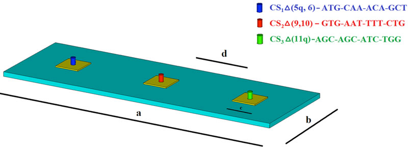
Figure 5. Unit cell of the sensing platform, comprised of three square gold patches, functionalized with three different Capture Sequences (depicted in blue, red, and green).

Figure 6. Ligand-receptor binding of three nanoparticles. Green, black and violet sections represent the Target Sequences for each nanoparticle.
the nanomachines have transmitted the own nanoparticles.
Figure 7(a) reported the extinction cross-section spectrum in the case of nanocube binding for the asynchronous case. We notice the peak of the extinction cross-section at  nm; this means that CS
 and PS
 are bound. In the case of rod and elliptical cylinder nanoparticles binding, under the assumption of asynchronous transmission, the obtained extinctions crosssection are shown in Figures 7(b) and (c), respectively. In Figure 7(b) we notice the peak of the extinction cross-section at
  nm meaning that CS
 and PS
 are bound, while in Figure 7(c) the peak is at
  nm, when CS
 and PS
 are bound.
As aforementioned, the electromagnetic response obtained from each nanoparticle must be different and independent in terms of resonant wavelength, amplitude and magnitude width, respectively. Figure 7 shows as the sensing platform could be efficiently applied for DNA alterations multi-detection. For each ligand-receptor binding, we notice a typical extinction cross-section which allow the nanoparticles multi-detection process. To demonstrate this ability, in Figure 8 the extinction cross-section is shown, for the case of three nanoparticles bindings. Obviously the sensor is able to recognize also no binding (see the red line in Figure 8).
The synchronous transmission can present other three binding combinations, such as the cases of 1) TS TS
TS , 2) TS
 TS
TS , and 3) TS
 TS
TS . Due to the geometry of the unit cell, the coupled effects among near nanoparticles are negligible and also each nanoparticle shows near electric field enhancement at the proper resonant wavelength. Figure 9(a) shows the near electric field distribution at the corresponding resonant wavelength of nanocube particle. In this way the sensing platform is able to recognize TS
 DNA alteration. Similar results are obtained for TS
 and TS
 DNA alterations. In fact, by observing the near electric field distributions at other specific resonant wavelengths we can see that specific nanoparticle is excited (Figures 9(b) and (c)).
5. Conclusions
In this paper, we presented the end-to-end model from the transmittion up to the reception of flows of nanoparticles for biomedical sensing applications. How nanoparticles diffuse is also investigated. The proposed model has been verified for the multi-detection of DNA alterations, specifically for the BRCA1 gene.
In our model, we considered three kinds of metallic nanoparticles (i.e., cube, rod, and cylinder), which can form a complex with chemical receptors. Based on a ligand-receptor binding, it is possible to detect DNA
 (a)
(a)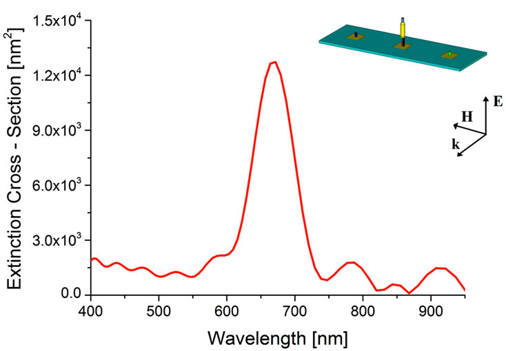 (b)
(b) (c)
(c)
Figure 7. Asynchronous detection. Extinction Cross-Section spectra obtained for (a) TS1, (b) TS2, and (c) TS3, only.
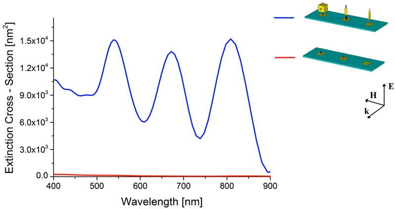
Figure 8. Synchronous detection. Extinction Cross-Section spectra obtained when all the target sequences are bound.
 (a)
(a) (b)
(b) (c)
(c)
Figure 9. Near electric field distribution of the sensing platform at (a) the cube resonant wavelength (542 nm), (b) the rod resonant wavelength (671 nm), and (c) the elliptical cylinder resonant wavelength (808 nm). The incident electric field amplitude is 1 V/m.
alterations and then obtain the extinction-cross section spectra, exploiting the LSPR phenomenon. Synchronous and asynchronous nanoparticle transmissions are allowed, while a selective reception process occurs.
Future work will address the use of the proposed end-to-end model in other scenarios, such as drug delivery for innovative therapeutic and diagnostic applications.