Received 25 March 2016; accepted 20 April 2016; published 18 July 2016

1. Introduction
Power quality refers to maintaining a sinusoidal waveform of bus voltages at rated voltage and frequency. The waveform of electric power at generation stage is purely sinusoidal and free from any distortion. Different types of linear and nonlinear loads such as the solid state controllers etc. connected to the bus may distort the waveform. These distortions may propagate all over the electrical network. Power quality problems in electrical systems mainly include voltage sag, voltage swell, voltage and current unbalance, flicker, harmonics, and power interruption [1] - [3] . These may cause abnormal operation of the facilities or even trip the protection devices. Power quality issues especially voltage unbalance, current unbalance and current harmonics have drawn much attention of researchers. Kazmierkowski, et al. proposed a various techniques for controlling the current using PWM technique to three-phase voltage source converter. Providing reactive power compensation can correct these power quality problems [4] [5] . The remedial options reported in the literature for these problems include the Static Var Compensators (SVCs), DSTATCOM, the Dynamic Voltage Restorer (DVR) or the Static Synchronous Series Compensators (SSSC) and the Unified Power Quality Conditioner (UPQC). The generic name for these devices is custom power devices [2] [3] [5] . Since 1970 SVC is the most popularly used device for power quality improvement. The development of high-power switching elements such as Insulated Gate Bipolar Transistors (IGBTs) and Integrated Gate Commutated Thyristors (IGCTs), Static Synchronous Compensators (STATCOMs) have been recognized as the next generation of compensators. The distribution level static synchronous compensator (DSTATCOM) is a newly developed STATCOM used in electric power distribution systems. Compared to existing SVCs, DSTATCOMs require less space, quicker response and more compact. It is also noted that recent research has shown that DSTATCOMs greatly enhance the low-voltage ride-through (LVRT) abilities of wind farms [1] [3] [5] [6] .
The DSTATCOM mitigates power quality problems by injecting current to the system. DSTATCOMs for three-phase four-wire systems with neutral conductor have been successfully developed at the customer end for unbalanced systems and reported in the literature [6] . However, DSTATCOMs for three-phase three-wire systems are still under investigation.
In this paper, Hysteresis Current Controller (HCC) method is used for designing the controller for DST- ATCOM to compensate unbalances in the system. This method transforms the asymmetrical voltages and currents of a three-phase system into set of balanced symmetrical components, namely positive sequence, negative sequence and zero sequence components of voltages and currents. The unbalanced currents have a more severe impact on the loads and the power system equipments. Hence, it is important to balance the unbalanced current to improve the power quality. A new and fast control technique is implemented in the DSTATCOM for compensating a three-phase three-wire unbalanced system.
This paper investigates a new method to compensate an unbalanced system. The existing controllers, namely PI controlled SPWM [6] , the PI controlled Space Vector Pulse Width Modulation (SVPWM) [7] and the Space Vector Modulation (SVM) based HCC [8] , are usually used only for a balanced system. These methods fail to compensate an unbalanced system. The unbalanced system is created by opening any one phase of the three- phase system. When the system becomes unbalanced, load voltages and load currents also become unbalanced. These unbalanced voltages and currents affect other sensitive loads in the three-phase systems due to negative sequence components present in it. The negative sequence component of the unbalanced currents is reduced using the DSTATCOM custom device with appropriate controllers. The performance of the controller is demonstrated by simulation.
2. Three-Phase System Configuration
Figure 1 shows a three-phase three wire system with a 3-phase delta connected load and a DSTATCOM. The DSTATCOM is connected in shunt with the load while the rest of the system is simplified as an infinite utility voltage source with a source impedance of Zs ( ). The DSTATCOM is connected at the point of common coupling (PCC) through the coupling inductor Lf. the DSTATCOM employs a voltage source converter (VSC) to convert the DC-link voltage Vdc of the capacitor into a voltage of adjustable magnitude and phase angle. Therefore, the DSTATCOM can be treated as a controlled voltage-source. In some applications, the DST- ATCOM can also be considered as a controlled-current source due to the Norton equivalent circuit representation. By providing a certain amount of reactive power, the DSTATCOM eliminates or mitigates the unwanted effects such as reactive power, harmonics, and unbalance in the load currents.
![]()
Figure 1. A three-phase three-wire distribution system with an unbalanced load and a DSTATCOM.
In a three-phase power system, voltages or currents are said be balanced if the amplitudes of the three-phase voltages or currents are equal and the phase-angles between the consecutive phases are equal to 2π/3 radians. There are two types of unbalances in a three-phase system, one is due to load unbalance and the other one is due to source unbalance. Power system generators or other unbalanced loads in the system cause the source unbalance. Unequal loads on each phases, open-circuit or short-circuit fault result in a load unbalance. During unbalanced condition, the unbalanced load currents IL drawn from the utility and hence affect the system. The DSTATCOM supplies the unbalanced currents to compensate for the load unbalance, which results in balanced currents being drawn from the utility, improving the power quality and thereby not affecting other loads connected to the system.
Let the total power required by the load is , the total power supplied by the source is
 ,and the total power supplied by the compensation is
 . The power balance equations for the real power and the reactive powers are given by the following Equations (1) and (2) respectively.
 (1)
(1)
 (2)
(2)
where,
PL is the real power required by the load,
PS is the real power supplied by the source,
PC is the real power supplied by the DSTATCOM,
QL is the reactive power required by the load,
QS is the reactive power supplied by the source
QC is the reactive power supplied by the DSTATCOM.
The reactive power supplied and absorbed by the DSTATCOM can be controlled by operating the DST- ATCOM in the capacitive and inductive modes respectively.
3. Proposed Compensation Scheme for DSTATCOM
For a three-phase three-wire system with an unbalanced load and a DSTATCOM as shown in Figure 1, the PI controlled SPWM or SVPWM methods cannot be used for compensation because it works on a balanced systems park’s transformation. The unbalanced voltages or currents are transformed into a set of balanced positive sequence, negative sequence and zero sequence components. Using these symmetrical components, a new controller is designed for compensating unbalances. The reference currents obtained from this method are used in the HCC to compensate the unbalances in the system.
The unbalanced load currents are extracted either from the power measurement by the two-wattmeter method or by a fast power detection method [9] - [11] . These methods are complicated, computationally intensive and indirect because the reference currents are extracted from the real and reactive power measurements. This paper proposes a simple method in which the voltages and currents are measured using sensors. These measured quantities may have unequal values in each phase because of the unbalanced loads present in the system. According to the symmetrical components method, the unbalanced voltages and currents are transformed into a set of balanced positive sequence components, negative sequence components and zero sequence components and then controllers are designed to mitigate the unbalances in the system.
Controller Design
To design the controller for three-phase three wire system, load voltages are transformed into positive and negative sequence voltages. Similarly, the load currents are transformed into positive and negative sequence currents. Since the load is delta connected, only the positive and negative sequence components exist, zero sequence components are not present. First, the symmetrical components transformation matrix [A] transforms the unbalanced load voltages into a set of balanced symmetrical components. Equation (3) defines the general relationship between the line voltages and the zero sequence voltage ( ), positive sequence voltage (
 ) and the negative sequence voltage (
 ). Similarly, Equation (4) transforms the three-phase load currents into their zero sequence current(
 ), positive sequence current (
 ) and the negative sequence current (
 ).
).
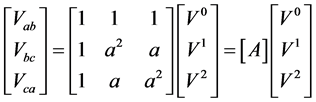 (3)
(3)
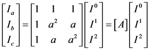 (4)
(4)
where, ![]() and
and
![]()
Using the above Equations (3) and (4), the sequence components of the voltages and the currents are given in Equations (5) and (6) respectively as follows.
![]() (5)
(5)
![]() (6)
(6)
where, ![]()
By applying the symmetrical components transformation to the load phase currents, Equations (7) and (8) transform the three-phase load currents to positive sequence load current and negative sequence load current respectively.
![]() (7)
(7)
![]() (8)
(8)
To compensate the unbalanced load currents as fast as possible, the DSTATCOM should supply the entire negative-sequence load currents and the imaginary part of the positive-sequence load currents as soon as possible [11] - [14] . Hence, the power source supplies only the real part of the positive-sequence load currents. Due to the delta-connected load, there will not be any path for the zero sequence currents in the three-phase three-wire system. Equations (9)-(11) give the command signals required for the current compensation. The DSTATCOM locally supplies the needed compensation currents for on-site load compensation.
![]() (9)
(9)
![]() (10)
(10)
![]() (11)
(11)
The design of sequence components based controller for the unbalanced system, the required magnitude and phase angle for the control purpose are computed using Equations (12)-(14).
![]() (12)
(12)
![]() (13)
(13)
![]() (14)
(14)
The phase locked loop (PLL) gathers the line frequency information at the point of common coupling (PCC). The reference magnitude of current ![]() is computed by comparing the actual capacitor voltage with the capacitor’s reference voltage and by controlling their error signal through a PI controller. Using these frequency and magnitude information signals, the reference sinusoidal current signals are generated as given by Equations (15)-(17). These three signals are compared with the three actual signals given in Equations (12)-(14)
is computed by comparing the actual capacitor voltage with the capacitor’s reference voltage and by controlling their error signal through a PI controller. Using these frequency and magnitude information signals, the reference sinusoidal current signals are generated as given by Equations (15)-(17). These three signals are compared with the three actual signals given in Equations (12)-(14)
![]() (15)
(15)
![]() (16)
(16)
![]() (17)
(17)
where,
![]() (18)
(18)
Figure 2 shows the complete block diagram of the proposed unbalanced load compensation scheme for the DSTATCOM. The three phase voltages (![]() ) and currents (
) and currents (![]() ) and DC-link capacitor voltages (
) and DC-link capacitor voltages (![]() ) are
) are
![]()
Figure 2. Block diagram of the controller of the DSTATCOM for an unbalanced load.
measured by sensors. the compensation scheme calculation shown in Figure 2 consist of converting three phase currents into positive and negative sequence currents using Equations (7) and (8) and generating command current signals using Equations (9) and (11). Using a phase-locked loop (PLL) generates the reference angle of the load bus voltage. The instantaneous compensation current command (![]() ) for the load compensation is obtained using Equations (12)-(14). In order to keep the DC-link voltage of the DSTATCOM at the assigned level, the DSTATCOM needs to absorb a small amount of active power from the grid to meet the switching losses and to charge the DC-link capacitor. A PI controller in the DSTATCOM regulates the instantaneous current |Ir| for the active power balance of the DSTATCOM, as shown in Figure 2 and given by Equation (18). The DSTATCOM is equivalent to a controlled current source, hence its output current is directly controlled by HCC. The Hysteresis Current Controlled inverter is used in the DSTATCOM for generating the compensation current and the overall compensation scheme of the DSTATCOM is now completed.
) for the load compensation is obtained using Equations (12)-(14). In order to keep the DC-link voltage of the DSTATCOM at the assigned level, the DSTATCOM needs to absorb a small amount of active power from the grid to meet the switching losses and to charge the DC-link capacitor. A PI controller in the DSTATCOM regulates the instantaneous current |Ir| for the active power balance of the DSTATCOM, as shown in Figure 2 and given by Equation (18). The DSTATCOM is equivalent to a controlled current source, hence its output current is directly controlled by HCC. The Hysteresis Current Controlled inverter is used in the DSTATCOM for generating the compensation current and the overall compensation scheme of the DSTATCOM is now completed.
4. Results and Discussions
The performance of the DSTATCOM’s controller is studied in simulation for compensating an unbalanced system. The power circuits designed with IGBTs switches are taken from the MATLAB/Simpower system blockset. Table 1 gives the simulation parameters.
Simulation is carried out for two different cases, one with compensation of an unbalanced load, and the other one with a change of balanced load from RC to RL.
4.1. Case-1: Compensation of an Unbalanced Load
For simulation studies, the unbalanced system is created by opening one of the phases of the three-phase system. Figure 3 shows the load current when the phase A is opened at time t = 0.2 s. the current in phase A is zero and in the other two phases having equal magnitude of currents with 180˚ phase difference. When load is balanced in all three phases, DSTATCOM supplies the balanced compensating currents and it supplies unbalanced currents when load becomes unbalanced. Figure 4 shows that the DSTATCOM supplies the balanced compensation currents until t = 0.2 s and after that the compensator currents are unbalanced. The DSTATCOM is controlled to compensate the unbalanced load currents. Hence, the current drawn from the source is balanced at all the times, as shown in Figure 5. During the unbalanced load condition, load requires negative sequence current, if it is drawn from source, it unbalances the source and affects other loads in the system. Hence compensator supplies more than 95% of the negative sequence load current and the rest of the negative sequence is supplied by source as shown in Figure 6.
![]()
Table 1. Simulation parameters of the DSTATCOM for compensating unbalances.
![]()
Figure 6. Negative sequence load currents (IL2).
It is clear from Figures 7-9 that the voltage at the PCC, the load voltages and the source voltages are balanced until time t = 0.2 s and then the unbalance arises due to unbalanced current supplied by the compensator or DSTATCOM. Figure 10 shows the positive sequence load current and the sum of the positive sequence current from the source and the positive sequence current from the compensator. For ideal compensation the positive sequence load current must be equal to sum of the positive sequence current from the source and the positive sequence current from the compensator. But in this case it not so because part of the source current is used for charging the capacitor. The active power required by the load is the sum of the active power from the source and the active power from the compensator as shown in Figure 11. However, the majority of the active power is supplied by the source. Similarly, Figure 12 shows that the reactive power required by the load is the sum of the reactive power from the source and the reactive power from the compensator, but the compensator supplies the majority of the reactive power. Thus, the DSTATCOM compensates the unbalanced load currents in addition to the reactive power compensation.
![]()
Figure 7. Unbalanced load voltages at the PCC.
![]()
Figure 14. Variation of negative sequence currents.
![]()
Figure 17. Variation of the bus voltage at the PCC for the change in load at t = 0.05 s.
4.2. Case 2: Change in Load from RC to RL
The controller designed based on the phase sequence method has a very good performance for compensating the unbalanced loads. The same controller performance is studied for a balanced load that changes from RC load to RL load. Figures 13-17 show the performance of the DSTATCOM when the balanced load changes from RC to RL. The load is varied from RC to RL at time t = 0.05 s. When the load is balanced, and changes from RC to RL, the power factor of the load changes from 0.8 leading to 0.8 lagging. Figure 13 shows the variation of the load current for this case. If the load is balanced, it does not require any negative sequence current during the steady state conditions, as shown in Figure 14. During the transition, when the load changes from RC to RL, the load requires a small negative sequence current. This negative sequence current is supplied by the DSTATCOM as shown in Figure 15, which keeps the source current constant, as shown in Figure 16. If the DSTATCOM is not present in the system, the RL (lagging power factor) load draws more power that is reactive from the source. The DSTATCOM supplies the required reactive power to the system and hence the current drawn from the source is maintained constant, as shown in Figure 16. To keep the source current constant during the load change, the DSTATCOM supplies the current with varying magnitude during the transition period, and is shown in Figure 15. During this transition period, the voltage at the PCC also varies while during the steady-state period, the voltage at the PCC is maintained constant as shown in Figure 17.
5. Conclusion
This paper presents the design and implementation of a DSTATCOM for compensating unbalances in a three- phase, three-wire distribution system. To satisfy the rapid response requirement, a new HCC based compensation scheme is employed using the symmetrical components method. Simulation results from the MATLAB/ Simulink software package show that the proposed symmetrical components based HCC method for the three-phase three-wire unbalanced system compensation has rapid response and an accurate compensation effect. This method of control is suitable for both unbalanced load compensation and for compensating the change of balanced load from RC to RL and vice-versa.
NOTES
![]()
*Corresponding author.