Numerical Simulation and Experimental Characterization of Clay Paste under Loads for Energy Saving in Clay Materials Processing ()
Received 23 February 2016; accepted 27 March 2016; published 30 March 2016

1. Introduction
Due to the recent requirements for the respect of the environment, the development of ecological construction materials has become a major challenge. The answer to this challenge is possible through the eco-design of bio- degradable materials, the development of low energy consumption processes in construction material industries. In the particular case of terra cotta materials such as tiles, bricks, floor tiles, the shaping of materials as well as their drying and firing, consume an important amount of energy. So, in spite of the biodegradability of these materials, their manufacturing doesn’t meet industrial requirements regarding the limitation of CO2 and NOx emissions.
This paper contributes to understand the rheological behavior of clay raw materials when hydrated in order to optimize clay pastes shaping by lowering the compaction energy demand and by increasing manufacturing productivity. In this study, Finite Elements analyzes will help us to understand if there is a piezo-dependence of the rheological behavior in the volume of the paste and the behavior at the interface between the clay structure and the extrusion die. These numerical analyzes will be coupled with an experimental study in order to obtain the properties of pastes flowing and to study effects of the extrusion pressures through axi-symmetric dies.
The correlation of results of both approaches will allow defining a low clay material shaping pressure that will contribute to reduce the loading energy consumed in clay materials industries.
2. Materials and Methods
2.1. Materials
2.1.1. Identification of Clay Pastes Viscosity
Clay minerals consist of two crystalline elements: a tetrahedral element (the silica, SiO2) and an octahedral element (aluminium hydroxide, Al(OH)3) [1] [2] . These elements are piled up to constitute the mineral layers. Their stacking determines the variety of clays.
Figure 1(a) shows the main clay minerals according to elements stacking (kaolinite, illite and smectites).
The clay paste rheological behavior is also related to the clay elements stacking. Due to the presence of water between mineral layers, these layers are sliding and the clay paste has plastic properties (Figure 1(b)) [1] - [3] .
Clay pastes are not purely viscous and have a much more complex rheological behavior which is similar to that of viscoelastic fluids of Bingham with a sliding on walls [4] .
- Below a certain stress threshold, the viscoelastic paste does not undergo a deformation.
- Above this stress threshold, it becomes deformed and the value of the stress is related to the paste shearing or flowing velocity. This stress threshold depends on the water content of the clay paste.
Indeed, due to the foliar structure of clay minerals, the paste flows by the sliding of layers between which there is water (Figure 2(a)). The stress threshold depends on the thickness of water layers.
Figure 2(b) shows a clay paste which is deformed between two plates. The down plate is fixed and the upper plate moves at a velocity V by an applied force F. The clay structure undergoes a shearing according to the de-
![]()
Figure 1. Mineral structure of main clay types (a) and clay paste macroscopic structure (b).
![]()
Figure 2. Deformation of clay paste by piled up layers sliding (a); flow velocity gradient in a clay paste (b).
formation direction. The shearing stress is expressed by Equation [5] :
 (1)
(1)
where S is the surface of each plate and F the force applied on the upper plate.
The gradient of the flowing velocity in the clay paste is expressed as [5] :
 (2)
(2)
where H is the clay paste thickness and V, the moving velocity of the upper plate.
In these conditions, the apparent viscosity of the clay paste is given by the expression [5] :
 (3)
(3)
2.1.2. Identification of the Clays Used
The apparent viscosity of the studied clays has been determined experimentally (Table 1) for the need of the finite element simulations. These average values reveal a major difference in the viscosity of studied clays.
The paper deals with six clay varieties which raw materials are processed and compressed to perform con- struction materials structures density. These raw materials coming from Togo are named according to their respective deposit name and their natural colours:
- ABB: White clay of Bangéli which is a kaolin;
- ANT: Black clay of Togblékopé;
- ARA: Red clay of Albi;
- ARG: Red clay of Guérin-kouka;
- ARK: Red clay of Kouvé;
- AVK: Green clay from Kouvé.
Clay raw materials are generally a natural mixture of the following main constituents [2] [6] : kaolin clay (which consists of aluminum oxide Al2O3, silica 2SiO2, water 2H2O), feldspar which provides sodium ion (Na+) and potassium ion (K+) that allow the formation of the vitreous phase when fired, a neutral solid constituent that reduces the shrinkage but does not act on the reactions during burning. The mineral elements contained in these clays are identified by x-rays. Table 2 gives the average contents values of three of the studied clays.
2.2. Methods
2.2.1. Numerical Identification of Clay Paste Flowing Parameters
Due to their visco-plastic likely behavior under load, clay pastes can be modeled by the law [7] [8] :
 (4)
(4)
where σ is the normal stress induced by the loading; k defines the paste consistency; ε is the generalized defor- mation of the paste;  is the generalized deformation velocity; m is the sensitivity coefficient to the velocity; n
![]()
Table 1. Average values of apparent viscosity of studied clays pastes.
![]()
Table 2. Mineral elements average contents of studied clays.
is the coefficient of the hardening.
By fitting the experimental curves of stress-strain σ(ε) with the law of Equation (4), the obtained parameters of this equation have the magnitude order of those typically given by the literature, namely:
 (5)
(5)
This law is based on the properties of the class of so called viscometric flows. In this case and for these flows, the stress tensor can be written, considering the axes in cylindrical coordinates, in the following form [9] [10] :
 (6)
(6)
Then, the measurement of the strain time rate permits to define three functions called viscometric functions and that define the behavior of the clay pastes [9] [10] :
 (7)
(7)
2.2.2. Mathematical Model of Clay Pastes Flowing
Due to the cylindrical shape of the molded clay samples, the equations are defined according to the cylindrical coordinates (r, q, z). Figure 3 illustrates these geometrical considerations. Due to the symmetrical and revolution shape, the non null stresses applied to a cylindrical element are srr, sqq, szz, trz and tzr (Figure 3(b)).
In this analysis of clay pastes flowing, we neglect the terms related to gravity, because of the high rigidity of the pastes when completely filled in the shaping cylinder. In the same way we consider only the case of sufficiently slow flows in order to neglect the inertial terms.
Under these conditions, the balance equations are written as following [6] [11] [12] :
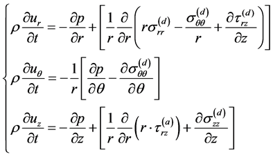 (8)
(8)
where ur, uq and uz are the velocity components according to the radial, tangent and axial directions, and p the loading pressure during the paste compaction.
With the assumption that the clay paste is incompressible, the continuity equation is expressed as follows:
 (9)
(9)
![]() (a) (b)
(a) (b)
Figure 3. Compaction of clay paste in two parallel plates (a) and stresses on a cylindrical element (b).
It is assumed that the law governing the fluid behavior may be written as:
![]() (10)
(10)
where ![]() is a function of invariants of the strain time rate tensor that is independent of the deformation history.
is a function of invariants of the strain time rate tensor that is independent of the deformation history.
The compression were also carried out on dried samples, in the condition of a low rate of deformation (about 0, 5 mm/min, to avoid an abrupt fracture of the sample) in order to locate and follow the materials cracking.
2.2.3. Finite Element Modeling of a Clay Paste Compression
The problem is axi-symmetric due to the samples cylindrical shape. The clay structure is supposed to be iso- tropic when compressed at a low displacement speed. The paste compression is simulated with the code ANSYS. To assess the efficiency of the simulation compared to the experimental approach, a numerical three dimension- al example was studied on a cylindrical shape sample loaded by a compression force Fz equal to 5 kN and 35 kN or a uniform pressure respectively of 7 MPa and 50 MPa. A 30 mm diameter sample is meshed with a 3D solid triangular element. The bottom of the sample is clamped and its top is considered as a rigid surface [13] [14] . The clay sample is compressed in a hollow solid cylinder which surfaces are clamped. Figure 4(a) shows the meshed sample under compression loading in the hallow cylinder and Figure 4(b) shows the corresponding ex- perimental device.
The calculation code doesn’t allow simulating the compression of viscoelasic pastes. In the present case, the simulation concerns the compression of clay structure that is considered to be an elasto-plastic and isotropic material. The modelling parameters are the Young modulus and the coefficient of Poisson associated with an asymmetric option and an incremental loading.
2.2.4. Samples Elaboration and Compression Tests Procedure
The raw material aggregates size plays an important role in the mechanical properties of the obtained paste. A paste with smaller particles sizes has a more high plasticity because the particles react more intensively between each other. Thus, studied clay raw materials were grinded. The resulted powders were kept at 60˚C during 24 hours in an oven until a complete dehydration. For the samples characterization, each clay paste is processed by mixing a mass m0 of anhydrous clay powder with a mass me of water. The resulting clay paste has an average water content v expressed as:
![]() (11)
(11)
where mws is the mass of the wetted sample and m0s the mass of the same sample when dried.
The masses were measured using a METTLE PJ 360 Delta Range balance, with an accuracy of 1/100 g.
For samples processing, an average water content v of about 18% was chosen in relation with the assessment of pastes fluidity, the consistency of pastes and the external appearance of samples after shaping. The water content
![]()
![]() (a) (b)
(a) (b)
Figure 4. A clay paste sample loaded by a uniform pressure in a cylindrical rigid container (a); corresponding device for the experimental shaping of samples by compression (b).
of the six varieties of studied clays ranges from 15% to 20%. These water content values lie in the limits set by ATTERBERG [12] [15] [16] .
To get a clay paste having satisfactory plasticity properties, the powder-water mixtures were kneaded for about 2 hours until getting a homogeneous paste. The paste is then stored in a hermetically climatic chamber for more than 24 hours, to insure a uniform moisture content while preventing evaporation and increasing the plas- ticity of the paste under the effect of micro-organisms that play an important role in the process.
Clay pastes were compacted by compression in a duralumin hallow cylinder shown in Figure 4(b). This cy- linder has an interior diameter of about f30 mm. The loading is made by a f30 piston. To meet the manufactur- ing requirements in tiles industrial factories, the clay structure must be compressed to present a density of about 2 g/cm3. For this purpose, to obtain samples having a height of 30 mm and a diameter of 30 mm, the mass of the paste to be introduced into the mould is calculated so to obtain a structure density of 2 g/cm3 after compression.
Compression is performed by imposing the piston motion at a low speed of 3 mm/min to avoid resistance re- lated to the viscosity of the paste. Clay pastes are subject to adhesion to the die walls in industrial processes, and this is also the case for the moulding carried out in this study. In most cases, friction is below the threshold at which shear occurs. Therefore, pastes slip instead of warping. This promotes good extrusion without lubricants [17] [18] . Several samples were processed (about 24 samples). Samples were loaded at 5 kN, 20 kN and 35 kN or respectively at compression stress of about 7 MPa, 28 MPa and 50 MPa.
3. Results and Discussion
3.1. Numerical Simulation
Figure 5(a) and Figure 5(b) give respectively the displacements field and the radial stresses field in the cylin- drical clay structure loaded at 7 MPa (corresponding to a compression force of 5 kN).
Figure 5(a) shows that the displacements field varies according to the loading direction. On the other hand, the distribution of the axial stresses (Figure 5(b)) is not uniform. These results show that the displacement and the radial stress decrease according to the loading direction, i.e., from the top to the bottom of the sample. This gradient of displacements and radial stresses distribution can be partially explained by shear stresses on the in- terface between the clay structure and the solid die cylinder resulting in an important friction on this interface. This friction generates micro-cracks that will widen during drying. The non uniform distribution of the dis- placements and the radial stresses generate also a non uniform drying shrinkage, resulting also in the structure cracking [2] [19] .
To verify the assumption of the influence of the interfacial friction on the non uniform distribution of the radial stresses and displacements, we simulate the case of a parallelepipedic shape sample. This block has the same loading face surface as the previous cylindrical sample. The loading force is increased up to 35 kN, i.e., a compression pressure of 50 MPa. Figure 6(a) and Figure 6(b) give respectively the displacements field and the radial stresses field in the parallelepipedic clay structure loaded at 50 MPa.
The results of Figure 6(a) and Figure 6(b) show that, near the bottom of the sample, the displacements and
![]()
![]() (a) (b)
(a) (b)
Figure 5. Displacement field (a) and radial stress field (b) in a cylindrical clay structure loaded at 7 MPa (5 kN).
![]()
![]() (a) (b)
(a) (b)
Figure 6. Displacement field (a) and radial stress field (b) in a clay block structure loaded at 50 MPa (35 kN).
the radial stresses are more or less important in the corners of the parallelepipedic sample, thus confirming the assumption of a gradient of displacements and stresses due to the friction of the clay structure on the solid die walls. Due to the concentration of displacements and stresses in the corners of the samples during the structure drying, the shrinkage on the corners differs from the shrinkage at the other points of the clay structure. This in- duces the structure cracking during drying, cracks starting by the corners.
Compared to Figure 5(b), the result of Figure 6(b) shows that the increase of compression loading lowers the non uniform distribution of the radial stresses. This reduces the structure cracking by shrinkage during drying.
Finally, following figures which correspond to the radial stress field of samples loaded respectively at 7 MPa (Figure 7(a)) and at 50 MPa (Figure 7(b)) show that the increase of the loading pressure decreases the size of the low stress zones (in blue) in the clay structure volume.
3.2. Sample Compression
The compression is performed with a conventional hydraulic traction-compression machine. The sample defor- mation and the loading force are recorded by computer devices during loading. Thus, the loading force Fz can
![]()
![]() (a) (b)
(a) (b)
Figure 7. Influence of the die shape and the loading pressure on the internal stress field: cylindrical shape sample loaded at 7 MPa (a) and parallelepipedic shape sample loaded at 50 MPa (b).
be plotted in function of the loading piston displacement Dz.
Figure 8(a) shows the curves of the loading force in function of the displacement in the case of samples of AVTK clay loaded at 5 kN, 20 kN and 35 kN. All studied clays have a similar mechanical behavior as curves shown by Figure 8(a). Figure 8(b) is the superimposed curves of studied clays loaded at 35 kN.
Referring to Figure 8(b), one observes that, if all curves have the same global evolution, they differ clearly:
- The most flat curve corresponds to the AVK clay which presents the most plasticity aspect;
- One can introduce a shape parameter to characterize Fz(Dz) curves, for instance the spreading factor å of the curve at a given loading force value. The spreading factors of curves in Figure 8(b) can be compared as follow;
![]() (12)
(12)
- The spreading factor decreases from the most plastic clay variety to less plastic one. The compaction rate of clays let suppose that the more plastic a clay paste is, the more resistant is its structure. This means that the spreading factor decreases from the most resistant clay structure to the less resistant one.
To verify this relation between a clay plasticity properties and its dried structure resistance, the compression tests were carried out on dried clay samples in order to determine their mechanical resistance. Figure 9(a) gives the stress-strain σ(ε) curves of AVTK dried clay samples previously shaped at 5 kN, 20 kN and 35 kN and Figure 9(b) gives superimposed stress-strain curves of dried samples of studied clays shaped at 35 kN.
Figure 9(a) shows that the mechanical resistance of the dried clay structures increases with the shaping loading force. But samples shaped at 20 kN and 35 kN have the same yield stress. This means that there is a shaping loading force limit over which the loading force does not increase the clay structure dry resistance. By considering the shaping loading force curves of Figure 8(a), one can estimate this limit around 10 kN or 14 MPa because above this value, the loading force increases linearly in function of the displacement. The deformation of the structure over this limit is no more plastic but it becomes reversible. The compaction of solid particles in the clay structure is completed when loading reaches 14 MPa. So, to shape clay based materials, the shaping loading force should not exceed 14 MPa. This allows saving the energy related to overloading.
The stress-strain curves of Figure 9(b) confirm partially the relation between the clay paste plasticity and the mechanical resistance of resulted dried structures. Except of the AVTK clay variety, the studied clays verify this ruler. But one should not forget that these samples must be fired in order to acquire a high mechanical resistance.
4. Conclusions
From the results obtained, it can be concluded as follows.
![]()
![]() (a) (b)
(a) (b)
Figure 8. Compaction curves of AVTK clay paste loaded at 5 kN, 20 kN and 35 kN (a) and super imposition of compaction curves of studied clay pastes loaded at 35 kN (b).
![]()
![]() (a) (b)
(a) (b)
Figure 9. Stress-strain curves of dried clay samples: case of AVTK clay samples shaped at 5 kN, 20 kN and 35 kN (a) and case of studied clays shaped at 35 kN (b).
The FE simulation giving the radial stress field in the clay structure loaded at 7 MPa or 5 kN and at 50 MPa or 35 kN is in accordance with the experimental loading curves. Indeed, when loaded at 7 MPa or 5 kN, the clay structure does not yet reach its completed compaction. But when loaded at 50 MPa or 35 kN, the structure compaction is completed and the radial stresses in the major part of the structure reach the loading pressure.
The shaping loading force was estimated around 10 kN or 14 MPa. Beyond this value the force of compaction has no effect even if it increases. Knowing this value, we can save the energy related to overloading.
But at this stage, it is difficult to establish a relation between the stresses field distribution and the clay structure cracking during drying. An improved FE model should allow predicting structure cracks occurring during drying.
The modeling of the present paper will be completed by simulations predicting thermo-chemical transformations occurring in clay structures during burning and inducing the structure hardening.