Dynamic, Charge Photogeneration and Excitons Distribution Function in Organic Bulk Heterojunction Solar Cells ()
1. Introduction
The active layer of organic solar cells is based on the concept of donor-acceptor heterojunction introduced by C. W. Tang to create a better charge separation [1] . This layer is a blend of an electrons donor (D) and an electrons acceptor (A). The most studied system which is referenced in an organic solar cells, is regioregular poly (3-hexylthiophene) (rrP3HT) (electron donor) blended with [6, 6]-phenyl C61-butyric acid methyl ester (PCBM) (electron acceptor) (rrP3HT-PCBM) [2] [3] . The area of the interface between the donor and the acceptor is enhanced and efficient exciton dissociation which can generate a higher short circuit current density JSC and a net increasing in the internal quantum efficiency [4] . Although the bulk heterojunction blend has been introduced to improve the device performance, the power conversion efficiency of polymer solar cells is still very low.
This energy conversion efficiency of about 10.7% obtained by Heliatek and M. A. Green et al., reached the high power conversion efficiency of 12% recently, and obtained on a standard size of 1.1 cm2 combining two different absorbing materials [5] . These materials generate high recovery photons, dramatically improving the energy conversion efficiency through a higher photovoltage signal in cells.
The electronic and optical properties such as the efficiency of photon absorption, the exciton dissociation rate and geminate recombination, exciton diffusion length and nongeminate bimolecular recombination can play important roles in the performance of organic bulk heterojunction solar cells [6] . The highest occupied molecular orbital (HOMO) of the donor and the lowest unoccupied molecular orbital (LUMO) of the acceptor can limit the open circuit voltage VOC, the short circuit current density JSC and therefore the efficiency of the device [7] - [9] . Better performances of solar cells based on P3HT-PC60BM have been obtained by increasing the regioregularity of P3HT [10] [11] . This improvement is explained by increasing the value of the internal quantum efficiency (IQE) due to greater absorption near infra-red.
Considerable interest for an improvement to the quantum efficiency conversion by incorporating plasmonic nanoparticles (NPs) in active layer of organic solar cells has been showed experimentally [12] - [16] . The results obtained reveal that the bulk heterojonction can be blended with plasmonic nanoparticles (NPs), which is a new composite material with new optical and electronic properties in the organic solar cells.
To determine the optical propagation in the organic solar cells, the transfer matrix method based on Maxwell’s equations is used by considering optical absorption of plasmonic active layers [17] . In order to obtain the electromagnetic field E(z) distribution at a depth z in the cell, the optical transfer-matrix theory (TMF) has been used. The light is treated as a propagating plane wave, which is transmitted and reflected on the interface. The complex reflection rij and transmission tij coefficients for a propagating plane wave along the surface normal between two adjacent layers j and k have been determined from Fresnel’s theory by considering the effect of optical interference [18] . All these research have been experimentally based on the optical properties of the charge photogeneration.
Recently, in order to understand the origin of the phenomena of surface losses, W. Yang et al. have defined quantitatively and calculated the loss probability of free charge carriers at the metal/organic (M/O) interfaces from numerical simulations [19] . They have found that the origin of surface losses is the free charge carrier extraction from the wrong electrodes, or the direct extraction or surface recombination of pair polaron without dissociation.
C. De Falco et al., for highlighting the role of the exciton dynamics in determining the transient activation time in organic photovoltaic devices, they carried out a temporal semi-discretization using an implicit adaptive method for the numerical treatment [20] . The resulting sequence of differential subproblems has been linearized using the Newton Raphson method with inexact Jacobian and exponentially fitted finite elements for spatial discretization.
However, there is very little theoretical works on the distribution theory of the phenomenon of the charge photogeneration and the excitons dynamic in organic bulk heterojunction solar cells. Moreover, charge photogeneration phenomenon, transport phenomenon, recombination and excitons dissociation into-free-charge, the surface loss of free charge carriers at the metal/organic (M/O) interface are important processes in the organic solar cells.
The objective of this paper is to study theoretically the photogeneration and excitons distribution function in the organic bulk heterojunction solar cells in order to understand the excitons dynamics in the cells. The charge continuity equation has been solved using Laplace transform and the residue theorem. Next, the influence of the Coulomb interaction between the electron and hole on the dissociation probability, the internal quantum efficiency, the binding energy distribution and efficiency of the excitons absorption have been analyzed and interpreted. The simulated results have been compared with those existing in the literature [18] - [20] .
The paper is organized as following: in Section 2, the architecture of the organic bulk heterojunction solar cell considered is described. Subsequently, a theoretical approach of the generation mechanism, recombination and dissociation of excitons in free charge carriers and excitons transport are presented. An overview of relevant equations and the solving of the charge continuity equation are shown. The simulated results and discussion are presented in Sections 3. Finally, the conclusion and outlook are listed in Section 4.
2. Material and Method
2.1. Architecture of the Organic Solar Cell
The structure of the solar cell considered, is blend of ITO/PEDOT: PSS/rrP3HT: PC70BM (1:0.7 weight ratio)/Yb/Al. The layer Yb/Al is cathode and ITO/PEDOT: PSS is anode. The ITO (85 nm) layer on glass is a transparent semi-conductor and serves of anode in the structure. It collects the holes after the separation of excitons and the charges transport. It is composed a blend of 90% indium oxide (In2O3) and 10% of tin oxide (SnO2). The ITO electrodes are covered with a film of PEDOT: PSS (40 nm) deposited by spin-coating from an aqueous solution. The PEDOT: PSS layer collects the holes and limits the electrochemistry between the active layer and the anode. It decreases the roughness of the ITO surface. PEDOT favours the holes transport but presents the drawback of being hydrophilic. rrP3HT: PC70BM (1:0.7 weight ratio) (100 nm) is the active layer; it is the seat of the charge photogeneration. PC70BM is a good electron acceptor; it presents a great chemical stability and good charge mobility. RrP3HT is used as the electron donor, it presents good electrical properties (good mobility of the charge carriers), good optical properties and an appreciable chemical stability for manufacturing of the organic photovoltaic devices. The Al/Yb layer collects the electrons and the aluminum (Al (200 nm)) layer presents a great surface roughness. Ytterbium (20 nm) layer limits electrochemistry between aluminum (Al) and sulfur of rrP3HT in film and allows improvement of open circuit voltage, shunt resistance and fill factor (FF). Ytterbium (Yb) forms a barrier layer between the active layer and aluminum (Al) [21] .
The BHJ blend is represented by the HOMO and LUMO levels of the donor and acceptor. The band offset between the LUMO levels of donor and acceptor guarantees the charge separation at the interface if the lifetime of the exciton is sufficiently long to meet a split site as shown in Figure 1. The choice of donor-acceptor pair defines the alignment of electronic levels of the system. This alignment is important because the energy difference between the HOMO of the donor and the LUMO of the acceptor is directly linked to the potential VOC of the solar cell while the energy difference between the LUMO of the two materials ensures exciton dissociation [22] [23] . The blend rrP3HT:PC70BM is chosen to indicate the interest of complementary absorption of PC70BM in active layer [24] .
2.2. Excitons Generation
The quantity energy of incident light absorbed by active layer of an organic solar cell depends on the complex index of refraction  of donor-acceptor materials [18] . The average energy dissipated per second for a given wavelength λ of incident light at the position z in the organic film can be calculated by:
 (1)
(1)
where c: is the vacuum speed of light, : the permittivity of vacuum, n: the real index of refraction,
 :
:
the absorption coefficient, and E(z): the electrical optical field at point z.  has the unit of W/m3 [25]
[26] .
Assuming that every photon generates one exciton, the exciton generation rate at position z in the material is:
 (2)
(2)
where h: is Planck constant, v: is the frequency of incident light.
We have modeled  by (Equation (3)):
 (3)
(3)
![]() (a) (b)
(a) (b)![]() (c) (d) (e) (f) (g)
(c) (d) (e) (f) (g)
Figure 1. (a) Ideal structure of the cell; (b) Band diagram of the cell ITO/PE DOT/rrP3HT: PCBM /Yb/Al proposed by our work; (c) Phenyl-C61-butyric acid methyl ester; (d) Methano-fullerene-[6,6]-phenyl-C71 methyl butyrate; (e) Regioregular poly(3-hexylthiophene); (f) Poly(ethylenedioxythiophene); (g) Poly(styrenesulfonic acid).
where  is the generation rate of singlet excitons depending on the incident light intensity, L: is the exciton diffusion length and
 : the absorption coefficient [27] [28] .
2.3. Generation and Excitons Recombination
In organic bulk heterojunction semiconductors, the mechanism of recombination is Langevin-type controlled by the mobility of the charge carriers [28] - [30] . The charge continuity equation is expressed as followed.
 (4)
(4)
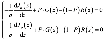
with q: the elementary charge, Jn(z) et Jp(z): the electron and hole current density at a depth z in the active layer, G(z): the photon absorption rate, P: the dissociation probability of charge carrier pair and R(z): the bi-molecular recombination rate from the Langevin model is:
 (5)
(5)
where n (z): electron density, p (z): hole density, : intrinsic carrier density,
 : electron mobility,
![]() : hole mobility,
: hole mobility, ![]() and
and![]() : spatial average static permittivity of active layer, respectively [29] [30] .
: spatial average static permittivity of active layer, respectively [29] [30] .
Incorporating both the drift and diffusion of charge carriers, we obtain the current density equations for electrons and holes, respectively:
![]() (6)
(6)
![]() : are the carrier diffusion coefficients given by the Einstein relation:
: are the carrier diffusion coefficients given by the Einstein relation:
![]() (7)
(7)
where ![]() is the Boltzmann constant and T: the absolute temperature.
is the Boltzmann constant and T: the absolute temperature.
The electric field distribution E(z) is determined by the Poisson equation
![]() (8)
(8)
The built-in voltage ![]() is determined by
is determined by
![]() (9)
(9)
where![]() : the external applied voltage and
: the external applied voltage and![]() : the active layer thickness [16] [31] [32] .
: the active layer thickness [16] [31] [32] .
To find the exciton distribution, the continuity equation can be applied with a one dimensional diffusion model for exciton movement, the generation rate from (Equation (1)) and recombination in the bulk becomes:
![]() (10)
(10)
where P: the excitons distribution, D: excitons diffusion constant, L: diffusion length.
Boundary conditions must be chosen to solve Equation (10) in each layer.
![]() (11)
(11)
where ![]() at the interface and S is the interfacial exciton-quenching velocity. S describes the recombination of excitons at the interface, and
at the interface and S is the interfacial exciton-quenching velocity. S describes the recombination of excitons at the interface, and ![]() corresponds to no recombination while
corresponds to no recombination while ![]() corresponds to complete quenching at the interface [27] . The Laplace transform is used to solve Equation (10) with the residue theorem.
corresponds to complete quenching at the interface [27] . The Laplace transform is used to solve Equation (10) with the residue theorem.
2.4. Resolution of Charge Continuity Equation
The solution of Equation (10) is obtained by determining its image using the residue theorem.
1) First case: let us assume that ![]()
The Laplace transform gives: ![]()
The image of Equation (10) is obtained by posing X = P and ![]()
![]() (12)
(12)
The original of Equation (12) solution of Equation (10) gives the excitons distribution function in the cell:
![]() (13)
(13)
2) Second case: ![]()
The Laplace transform gives ![]()
The image of Equation (10) is obtained:
![]() (14)
(14)
The original of Equation (14), solution of Equation (10) gives the excitons distribution function in the organic cell:
![]() (15)
(15)
3) Third case: we took into account, the excitons field dependent mobility parameter then we have: ![]() with
with ![]() where
where![]() : excitons generation length,
: excitons generation length,![]() : excitons dissociation length.
: excitons dissociation length.
The Laplace transform is expressed as followed: ![]()
The image of Equation (10) is given by:
![]() (16)
(16)
The original of Equation (16), solution of Equation (10) gives the excitons distribution function in the organic solar cell according to the residue theorem.
![]() (17)
(17)
2.5. Generation and Excitons Dissociation into Tree-Charge Carriers
The photon absorption by an organic material generates in the majority of cases an exciton of Frenkel-type. These excitons photogenerated, not all of them can be dissociated into-free carriers. In our numerical simulation, the field dependency of charges generation is processed by the Onsager-Braun model which gives the probability of electron-hole pair dissociation [33] - [36] .
![]() (18)
(18)
![]() : is the rate of charge transfer recombination and
: is the rate of charge transfer recombination and![]() : the dissociation rate of a bound electron-hole pair.
: the dissociation rate of a bound electron-hole pair.
![]() (19)
(19)
where a: the electron-hole separation distance,![]() : electron-hole pair binding energy described as
: electron-hole pair binding energy described as![]() ,
,![]() , T: the temperature, E: the electric field,
, T: the temperature, E: the electric field,![]() : the dielectric constant of the material,
: the dielectric constant of the material,![]() : spatial permittivity,
: spatial permittivity,![]() : the bimoleculare recombinaison rate of Langevin and
: the bimoleculare recombinaison rate of Langevin and ![]() is the Bessel function of order 1.
is the Bessel function of order 1. ![]() is the efficiency of dissociation given by Onsager-Braun [33] [34] , where
is the efficiency of dissociation given by Onsager-Braun [33] [34] , where![]() .
.
Taking into account the disorder in the blend, a distribution of the excitons probability having different separation distances have been incorporated into the numerical simulations [34] [35] . As a result, Equation (18) should be integrated over a distribution of separation distances:
![]() (20)
(20)
where f(a, z) is a normalized distribution function given by:
![]() (21)
(21)
![]() is the dissociation probability at a specific distance z in an organic solar cell. The procedure used for the numerical simulations has been described in detail by [37] .
is the dissociation probability at a specific distance z in an organic solar cell. The procedure used for the numerical simulations has been described in detail by [37] .
2.6. Generation and Excitons Transport
Charge transport in the organic solar cells device is governed by the set of continuity equations [19] [37] - [42] .
![]() (22)
(22)
where n and p: electrons and holes density, ![]() and
and![]() : electrons and holes flux density,
: electrons and holes flux density, ![]() and
and![]() : charge carriers generation rate,
: charge carriers generation rate,![]() : the total current density,
: the total current density, ![]() and
and![]() : electrons and holes recombinaison rate.
: electrons and holes recombinaison rate.
The charge carriers’ flux density is given by:
![]() (23)
(23)
where E: electric field, ![]() and
and![]() : the charge carriers mobility and the electric field distribution E(z) is determined by the Poisson equation (see Equation (8)):
: the charge carriers mobility and the electric field distribution E(z) is determined by the Poisson equation (see Equation (8)):
![]() (24)
(24)
We denote by X(z) the volume density of geminate pairs and we express its rate of charge as:
![]() (25)
(25)
where![]() : dissociation constant,
: dissociation constant,![]() : recombination constant,
: recombination constant,![]() : the speed at which excitons reach interfaces and partially are separated,
: the speed at which excitons reach interfaces and partially are separated,![]() : the speed at which free electrons and holes are attracted to each other and recombine,
: the speed at which free electrons and holes are attracted to each other and recombine,![]() : Langevin constant.
: Langevin constant.
2.7. Boundary and Initial Conditions
![]() are needed to complete the model. at the interface
are needed to complete the model. at the interface ![]() therefore
therefore![]() .
.
The Equation (22) and Equation (25) become:
![]() (26)
(26)
where![]() .
.
![]() (27)
(27)
After substituting Equation (27) into Equation (10) and imposes to Equation (23), the condition:
![]() and,
and,
we have:
![]() (28)
(28)
The Laplace transform gives the images of Equation (28) for the electrons and holes:
![]() (29)
(29)
![]() (30)
(30)
The originals of Equation (29) and Equation (30) solution of Equation (28) gives the distribution function of the electrons and holes:
![]() (31)
(31)
![]() (32)
(32)
The excitons distribution function in the cell is given by the relation:
![]() (33)
(33)
Taking into account the absorption coefficients ![]() and
and ![]() of the donor and acceptor
of the donor and acceptor![]() , the current density distribution function for the electrons
, the current density distribution function for the electrons ![]() and holes
and holes ![]() are given by:
are given by:
![]() (34)
(34)
![]() (35)
(35)
where
![]()
![]()
![]()
![]()
The excitons photogenerated distribution function in the active layer is given by:
![]() (36)
(36)
3. Results and Discussion
3.1. Excitons Distribution Function in the Cell
Parameters used in the device model simulations: a = 1.8 nm: electron-hole separation distance in the CT state,![]() : optical generation rate, T = 300 K: the temperature,
: optical generation rate, T = 300 K: the temperature,![]() : effective band gap of P3HT and 2.4 eV: effective band gap of PCBM, the mobilities of holes and electrons in P3HT:PCBM (1:0.7 by weight) are
: effective band gap of P3HT and 2.4 eV: effective band gap of PCBM, the mobilities of holes and electrons in P3HT:PCBM (1:0.7 by weight) are ![]() and
and![]() ,
,![]() : relative dielectric constant, L = 10 nm: length diffusion,
: relative dielectric constant, L = 10 nm: length diffusion,![]() : constant diffusion,
: constant diffusion,![]() : recombination rate and
: recombination rate and![]() : dissociation rate
: dissociation rate![]() : effective lifetime,
: effective lifetime,![]() : device area, Iirr = Io = 100 mW・cm−2:
: device area, Iirr = Io = 100 mW・cm−2:![]() : short circuit current density,
: short circuit current density,![]() : open circuit voltage,
: open circuit voltage,![]() : the built-in voltage,
: the built-in voltage,![]() : series resistance,
: series resistance,![]() : shunt resistance, FF = 50.3%: fill factor, h = 2.43%: power conversion efficiency and the voltage applied to the cell is between −0.54 V et 0.54 V,
: shunt resistance, FF = 50.3%: fill factor, h = 2.43%: power conversion efficiency and the voltage applied to the cell is between −0.54 V et 0.54 V,![]() : the holes diffusion length,
: the holes diffusion length,![]() : the electrons generation rate,
: the electrons generation rate,![]() : the holes generation rate,
: the holes generation rate,![]() : the electrons diffusion constant,
: the electrons diffusion constant,![]() : the holes diffusion constant,
: the holes diffusion constant, ![]() absorption coefficient of electrons and holes,
absorption coefficient of electrons and holes,![]() : the excitons generation length,
: the excitons generation length,![]() : excitons dissociation length and
: excitons dissociation length and![]() : field dependent mobility parameter.
: field dependent mobility parameter.
Figure 2 and Figure 3 show the evolution of excitons distribution function as a function of the organic layer thickness. They are obtained for![]() , L = 10 nm,
, L = 10 nm, ![]() ,
, ![]() and
and![]() .
.
Figure 2 is obtained from Equation (13) after resolution of Equation (10) where the excitons generation rate is constant in the cell and Figure 3 is obtained from Equation (15) after resolution of Equation (10) where the excitons generation rate is modeled by![]() .
.
![]()
Figure 2. Excitons distribution function as a function of the organic layer thickness.
![]()
Figure 3. Excitons distribution function as function of the organic layer thickness.
We first note that the distribution remains constant whatever the variation of the organic thickness layer. Next, it decreases linearly with an abrupt variation of the organic layer thickness.
This linear decreasing is due to the excitons loss mobility in the cell; there are drift of charges. This factor can be attributing to the loss of free charge carriers at the electrodes/organic (M/O) interfaces. It causes an increasing of the interfacial dissociation rate and a diffusivity of the electron-hole pair at D/A interface. This result has been obtained by W. Yang and al [19] . In addition, this result is consistent with the finding that there is a loss of open circuit voltage when LiF/Al is employed as the cathode which can form Ohmic contact with the PCBM active layer [43] . The underlying mechanism is attributed to the band (or carrier transport level) bending near the metal-organic interface. This effect was investigated by Cheyns et al for planar bulk heterojunction solar cells [44] . As to the loss of open circuit voltage under the large mobilities, it is attributed to the nonselective character of the metal/organic contacts by Tress et al. [45] . Thus this problem can be overcome by inserting blocking layers between the metal electrode and the organic active layer to form selective contacts. With selective contacts the surface losses are suppressed and the device performances are always improved under higher mobilities. Therefore the reduction of open circuit voltage is compensated. In definitive, we note the decreasing of fill factor, which results from the drastic bimolecular recombination and thus signifies remarkable internal losses in the cell. The opposite phenomenon is observed on Figure 3 where the excitons photogenerated are dissociated normally at D/A interface for being collected at the electrodes. When the mobility parameter of the excitons is considered, we obtained the same results as shown in (Equation (17)) that those obtained in the case of Figure 3. Therefore, this result reveals that the mobility coefficient is not more important parameter which influences the optoelectronic properties in the organic photovoltaic devices, which confirms the validity of our model.
3.2. Excitons Generation Rate Distribution in the Active Layer
Considering the organic layer as an homogeneous material, the simulated results show that the excitons generation rate decreases with the increasing of the active layer thickness as described in Equation (3), which makes the corresponding average exciton generation rate (total exciton generation rate divided by the thickness) become smaller. However, when we took into account the excitons mobility, on remarked that, at the initial stage, the average exciton generation rate increases with the increasing thickness of the active layer as shown in Figure 4. With the further increase of the active layer, the average generation rate becomes larger and decreases very rapidly although other photo-generation peaks appear in the active layer as shown in Figure 5. This is be-
![]()
Figure 4. The calculated exciton generation rate in the active layer. Star: the total excitons generation rate, Circle: the average excitons generation rate in the structure.
![]()
Figure 5. Current density function as a function of the active layer thickness. It repre- sents the curve obtained from Equation (36) after substituting Equation (34) and Equation (35) into Equation (22).
cause the absolute values for the peaks become small, which leads to the corresponding decrease of average exciton generation rate.
Moreover, when the active layer thickness increases from 20 to 50 nm, the total excitons generation rate increases from![]() . This rate decreases very slightly from
. This rate decreases very slightly from ![]() with the increasing of the active layer between 70 and 130 nm and increases again with the further increase of the active layer. Whereas we remarked the net increasing of average exciton generation rate between
with the increasing of the active layer between 70 and 130 nm and increases again with the further increase of the active layer. Whereas we remarked the net increasing of average exciton generation rate between ![]() with the increasing of the active layer from 20 to 50 nm, which decrease very rapidly and reaches a rate from
with the increasing of the active layer from 20 to 50 nm, which decrease very rapidly and reaches a rate from ![]() with the further increases of the active layer. As a result, when the active layer thickness increase, the excitons generation rate increase. This result reveals the increasing of the photons absorption rate and the excitons mobility rate in the active layer. This result has been proved experimentally by C. Zhang and al [18] by considering the optical interference effect in the active layer and theoretically predicted by C. De Falco et al. [20] .
with the further increases of the active layer. As a result, when the active layer thickness increase, the excitons generation rate increase. This result reveals the increasing of the photons absorption rate and the excitons mobility rate in the active layer. This result has been proved experimentally by C. Zhang and al [18] by considering the optical interference effect in the active layer and theoretically predicted by C. De Falco et al. [20] .
3.3. Current Density Distribution Function in the Active Layer
Figure 5 shows the current density ![]() distribution function of the excitons photogenerated in the active layer. It represents the curve obtained from Equation (36) after substituting Equation (34) and Equation (35) into Equation (22). The principal generation of the photocurrent is localized in the active layer. Because of the very high optical absorption ability of organic materials, the active layer is very thin and typically from several ten to several hundred nanometers. For a well blended layer, the length scale of donor (D) and acceptor (A) phases is smaller than the exciton diffusion length (typically less than 10 nm), so that most of the generated excitons can diffuse to the D/A interface before they decay. Therefore, when the active layer thickness lower than 1nm, the light absorption in the active layer decreases, the electric field in the blend layer decreases, which lowers down the exciton-to-free-carrier probability and makes charge collection less effective simultaneously (See Figure 2 and Figure 3). This result has been obtained by [25] [35] , which have shown experimentally that to obtain a higher JSC, both the optical and the electric properties should be considered at the same time.
distribution function of the excitons photogenerated in the active layer. It represents the curve obtained from Equation (36) after substituting Equation (34) and Equation (35) into Equation (22). The principal generation of the photocurrent is localized in the active layer. Because of the very high optical absorption ability of organic materials, the active layer is very thin and typically from several ten to several hundred nanometers. For a well blended layer, the length scale of donor (D) and acceptor (A) phases is smaller than the exciton diffusion length (typically less than 10 nm), so that most of the generated excitons can diffuse to the D/A interface before they decay. Therefore, when the active layer thickness lower than 1nm, the light absorption in the active layer decreases, the electric field in the blend layer decreases, which lowers down the exciton-to-free-carrier probability and makes charge collection less effective simultaneously (See Figure 2 and Figure 3). This result has been obtained by [25] [35] , which have shown experimentally that to obtain a higher JSC, both the optical and the electric properties should be considered at the same time.
Figure 6 revealed that, when the active thickness increases from 20 to 80 nm, ![]() reaches its maximum value, and followed by a little decrease until 145 nm and increases again until 225 nm and behaves wavelike. When the thickness increases further,
reaches its maximum value, and followed by a little decrease until 145 nm and increases again until 225 nm and behaves wavelike. When the thickness increases further, ![]() increases again. Which reveals that
increases again. Which reveals that ![]() should be proportional to the total exciton generation rate and all the excitons photo generated can be dissociated into free charge carriers and then collected by the electrodes.
should be proportional to the total exciton generation rate and all the excitons photo generated can be dissociated into free charge carriers and then collected by the electrodes.
Moreover, when the active layer thickness increases, ![]() increases and unfortunately, there is obvious deviation between our results and prediction. This deviation is due to the low excitons dissociation probability rate
increases and unfortunately, there is obvious deviation between our results and prediction. This deviation is due to the low excitons dissociation probability rate
![]()
Figure 6. Density current as a function of the active layer thickness. (Circle: experimental are extracted from [22] ), (Star: theoretical not considering exciton to free carriers probability).
into free charge carriers with the increasing of the active layer thickness. These results have been obtained experimentally by [18] [24] . Obviously, the assumption that the exciton-to-free-carrier dissociation probability is unity is not totally correct.
3.4. Distribution of Internal Quantum Efficiency-Excitons Dissociation Probability
Figure 7 and Figure 8 translated the internal quantum efficiency distribution (IQE) and excitons dissociation probability respectively as a function of a specific distance z in the organic layer. When the electron-hole separation distance “a” increases, the excitons dissociation probability decreases and the internal quantum efficiency increase which considerably improves the current density in the cell. This result reveal, a feeble Coulomb interaction between the electron and hole, a decreasing of the supplemental strength for dissociate the excitons by heat-energy at ambient temperature, a low exciton binding energy and a drop in internal electric field. In this
![]()
Figure 7. Internal quantum efficiency (IQE) as a function of the organic layer thickness: the curves are obtained for different valor of the electron-hole pair separation distance “a”. Star: (a = 1. 95 nm), Diamond: (a = 1. 64 nm), Circle: (a = 1; 42 nm) and Square: (a = 1; 25 nm).
![]()
Figure 8. Excitons dissociation probability at a specific distance z in the organic la- yer: the curves are obtained for different valor of the electron-hole pair separation distance “a” by exploiting the Equation (18), Equation (20) and Equation (21).
work, a = 0.92 nm as shown in Figure 8 gives a better excitons dissociation for a probability equal to unity and for the values of “a” greater than 2 nm, the excitons dissociation into-free-charge carriers is very feeble. Therefore the electron-hole separation distance is a key parameter for an effective dissociation of the excitons at D/A interface.
We determined the distribution function of the excitons binding energy (UB) and external quantum efficiency (EQE) as a function of the photons absorption energy by varying the electron-hole pair separation distance “a” Figure 9. The simulated results reveal that when the photons energy increases, the binding energy decreases. This behavior confirms the previous results as shown in Figure 7 and Figure 8. Furthermore, the Coulomb at- traction and the exchange energy dramatically depend on the separation distance between electron and hole. Experimental results show that the exchanged energy for the intramolecular excitonic states is around 0:7 eV [46] . For the cases of polaron pair state and charge-transfer complex state, the situation would be different mainly due to the electron hole pair separation distance.
4. Conclusions and Outlook
We determined the excitons distribution function in an organic bulk heterojunction solar cell ITO/PEDOT: PSS/rrP3HT: PC70BM (1:0.7 weight ratio)/Yb/Al using the Laplace transforms with the residue theorem. The influence of the electron-hole pair separation distance on the excitons dissociation probability, the quantum efficiency of charge carriers generation, the current density photo-generated on the excitons binding energy have been studied.
The simulated results indicate that the linear decreasing of the excitons generation function is attributed to the loss of free charge carriers at the electrodes/organic (M/O) interfaces. It causes the increasing of the interfacial dissociation rate and a diffusivity of the electron-hole pair at D/A interface. The result is consistent with the finding that there is a loss of open circuit voltage when Yb/Al is employed as the cathode which can form Ohmic contact with the PCBM active layer. We remarked that the total exciton generation rate does not monotonously increase with the increasing of the active layer thickness, but behaves wavelike which induces the corresponding variation of![]() . The carrier lifetimes also influence
. The carrier lifetimes also influence ![]() greatly. When the lifetimes of both electrons and holes are long enough, dissociation probability plays an important role in the thick active layer.
greatly. When the lifetimes of both electrons and holes are long enough, dissociation probability plays an important role in the thick active layer. ![]() behaves wavelike with the variation of the active layer thickness. In addition, the excitons dissociation probability decreases exponentially when the electron-hole pair separation distance increases and the internal quantum efficiency charge generation monotonously increases.
behaves wavelike with the variation of the active layer thickness. In addition, the excitons dissociation probability decreases exponentially when the electron-hole pair separation distance increases and the internal quantum efficiency charge generation monotonously increases.
![]()
Figure 9. Distribution function of the excitons binding energy (UB) and external quantum efficiency (EQE) as a function of the photons absorption energy. Diamond: binding energy (UB) and Star: external quantum efficiency (EQE).
Our results are in agreement with those predicted by the literature. Moreover, the phenomena of charge generation and the excitons dissociation into-free-charge carriers are important processes in organic bulk heterojunction solar cells. The potential improvement of the internal quantum density of charge generation depends on the exciton dissociation probability into-free-charge carriers and strongly depends on the photons optical absorption.
Future work can be about:
1) extensions to the model; 2) improvement of the analytical results and 3) the model study as a stochastic processes using Fokker Planck equations.
Acknowledgements
We thank Professor Jean Chabi Orou, Dr. Amoussa S. Hounkpatin, MC. Basile Kounouhéwa, Dr. M. Ossénath, Dr. K. N’GOBI Gabin and Dr. Luis Adébayo Essoun for reading the manuscript. We acknowledge the financial supports by the Trading Company SOCOMA-Benin, “Ecole Doctorale Sciences des Matériaux (EDSM)” and “Laboratoire de Physique du Rayonnement LPR, FAST-UAC 01BP 526 Cotonou, Benin”.
NOTES
*Corresponding author.