Evaluating the Performance of Fault-Tolerant S2A vs. In-Loop Controller Models for Ethernet-Based NCS ()
1. Introduction
Manufacturing control has been moving more and more towards distributed implementations of control systems. Networks are used to communicate the data instead of using traditional point-to-point communication. Networks require less wiring and less maintenance compared to a point-to-point architecture. Such networks carry a large number of small control signals between many nodes and these signals have to meet the delay constraints of real-time control systems. The main difference between such control networks and conventional data networks is that control networks must be able to support time-critical applications [1] .
Networked Control Systems (NCSs) consist of sensors, controllers and actuators that communicate together over a network. Sensors send packets to the controllers which calculate the control action that should be delivered to the actuators, and these transmissions must meet the control system’s deadline. There are four factors that affect the utilization of the network bandwidth: the sampling rate, the number of nodes requiring synchronous operation, the size of the information sent and the protocol used. Traditionally, for proper control, there are different protocols used which have a deterministic behavior such as DeviceNET and ControlNET [2] [3] . Also, many real-time applications were studied using protocols such as Controller Area Network (CAN), PROFlBUS and EtherNet/IP which is a merger between Ethernet and ControlNET [3] -[7] .
Recently, Ethernet has been used in Networked Control Systems. Although Ethernet is a nondeterministic protocol, it was shown, in many studies, that it can be used in NCSs [1] [8] -[19] . Ethernet is widespread nowadays in communication systems because it has been proven to be a very successful protocol. By using such a protocol, installation and maintenance costs can be reduced in industrial applications. In [10] , real-time as well as non-real time traffic were integrated without any changes to the IEEE 802.3 protocol. It was shown that a system consisting of 16 sensors, one controller and 4 actuators was able to meet the required time constraints. The system was running on-top-of Gigabit Ethernet. On the other hand, in [20] , it was shown that an architecture with a integrated control design was also a possible solution where each actuator would have its own controller integrated in the same node instead of one controller for the entire system as in [10] . This same concept is implemented in Sensor Actuator Networks (SANETs) where a group of sensors and actuators are distributed geographically and communicate together through wired or wireless networks [21] -[23] .
Different fault-tolerance techniques were applied previously on the node level in Networked Control Systems. A supervisory control level is essential in many distributed control systems where the functions are hierarchal. The role of this level is monitoring the control objectives and supporting the overall coordinated control in different phases of normal operation. Also, this level allows the diagnosis of all foreseeable faults, takes the necessary corrective actions, including the change of controller parameter or structure [24] . In [25] , a hierarchical control architecture was discussed where a supervisor operated on top of separate controller nodes. It was shown via simulations that the system was fully functional. Fault-tolerance was added to these aforementioned architectures and reliability/availability models were used to quantitatively assess the increase in lifetime [26] [27] . In [28] , actuator fault-tolerant architecture was presented in order to detect all relevant faults of an electrical steering system by using a double stator AC motor instead of duplicated motors. The paper showed how active control reconfiguration can accommodate all critical faults which were demonstrated on the hardware of a warehouse truck. There are other ways of analyzing the fault-tolerant problem for the networked control systems (NCSs) such as using fuzzy models [29] . A Takagi-Sugeno (T-S) fuzzy model with parametrical uncertainties was used to approximate the T-S model where robust controllers were designed with sensors or actuators failure. It was shown via simulations that the method is effective and the system can be kept asymptotically stable under some sensors failures or actuators failures.
The focus in this research is the development of new architectures where fault-tolerance techniques are applied and studied on the controller level using unmodified Fast Ethernet and Gigabit Ethernet as they have sufficient bandwidth to easily handle the data volume. Two architectures will be studied; the first is an in-loop controller architecture while the second is a direct Sensor to Actuator (S2A) architecture. Additionally, a performance comparison in terms of the total end-to-end delay between the two architectures, will be carried out in the fault-free scenario and the scenario where there are failed controller(s).
The rest of the paper is organized as follows. Section 2 presents more details about related work. Section 3 elaborates on the new proposed models. In Section 4, the simulation results are presented and discussed. Finally, the paper is concluded in Section 5.
2. Previous Work
In [20] , NCSs were studied where actuators would have their own control function; it was shown that this integrated approach to the design of real-time fieldbus-based distributed control systems was successful in meeting control requirements. At first, the performance of the system suffered severe degradation, but architecture and control co-design were used to achieve a successful implementation of this distributed system. In [10] , real-time and non-real time traffic were integrated in an NCS without any modifications to the IEEE 802.3 protocol packet format. It was shown in a mixed traffic industrial environment that standard Gigabit Ethernet succeeds in meeting timing constraints. In [30] , a new model was developed; it has 16 sensors and 4 actuators as in [10] . However, each sensor communicates with the appropriate actuator(s) directly without going through a controller node. In other words, each actuator incorporates its own control function as in [20] . This proposed system was studied on-top-of both Fast and Gigabit switched Ethernet. It was shown that this architecture succeeds in meeting the required time constraints. Then, the architecture was compared to the architecture in [10] and it was shown, via OMNeT++ [31] simulations, that the observed end-to-end delay is smaller in the proposed architecture. Finally, it was shown that the proposed model can withstand more additional load than a system with an in-loop controller as in [10] .
In this paper, new models are developed where the focus is on applying fault-tolerance techniques on the control level of both architectures in [10] and [30] . These fault-tolerance techniques will increase the reliability of the architectures as well as their lifetime. New models are developed on-top-of both Fast and Gigabit switched Ethernet. Comparison is made between the two proposed models via OMNeT++ simulations where the focus is on factors such as the number of packets dropped and the observed end-to-end delay.
3. Proposed Models
In this section, a comparison is made between two different control network fault-tolerance models. The in-loop fault-tolerant model is based on the one in [10] while the S2A one is based on [30] . In the in-loop model, there are two controllers which receive the packets from the sensors and only one of them sends control packets to the actuators while the other one is in hot-standby mode as shown in Figure 1. In the S2A model, a supervisor is responsible for monitoring network behavior by receiving packets from all the different nodes in the network as shown in Figure 2. The controlling process in the in-loop model takes place in an individual controller node, while in the S2A model it takes place in the smart actuator node(s) which are more intelligent nodes where both the control and actuation processes occur. To incorporate fault-tolerance into the S2A model, two controllers will be used per actuator where both controllers receive packets from the sensors but only one of them is chosen, via a multiplexer, to send the control packets to the actuators as shown in Figure 3. Both models are operated under Fast or Gigabit Ethernet links where the focus is on the packets dropped and the observed end-to-end delay. Note that the end-to-end delay includes all types of encapsulation/decapsulation, propagation and queuing delays.
3.1. Models Description
The in-loop fault-tolerant model is based on the one used in [10] as shown in Figure 1. It consists of 16 sensors, two controllers and 4 actuators. All 16 sensors send their data to both controllers where one of them is active and the other one is in hot-standby mode. The active controller then computes the control action and transmits it to the 4 actuators. Both controllers send watchdog signals to each other and if the active controller fails, the hotstandby controller will be alerted via the absence of the watchdog signal; therefore, it would take over and become the active controller.

Figure 1. Fault-tolerant in-loop model architecture.

Figure 2. Fault-tolerant S2A model architecture.
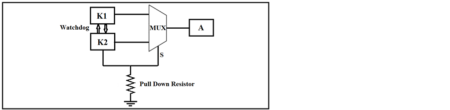
Figure 3. Fault detection and recovery mechanism (S2A model).
The S2A model also consists of 16 sensors which send data directly to the 4 actuators but instead of a controller, a supervisor is used; all sensors and actuators send packets to the supervisor node which is responsible for monitoring the behavior of the network. The S2A fault-tolerance model is based on the one used in [30] as shown in Figure 2. Each one of the actuators will have two controllers integrated in the same node. The two controllers receive data from the 16 sensors and send watchdog signals to each other. They are connected to the actuator (A) via a multiplexer integrated in the same node on a circuit board as shown in Figure 3. In a fault-free scenario, the first controller (K1 in Figure 1) is working and sending data to the actuator while the second controller is inactive by sending “0” to the selection line (S) of the MUX in order not to be chosen. Upon the failure of the first controller, the second one will be alerted via the absence of the watchdog signal; therefore it would send a “1” to the selection line of the MUX to be chosen and becomes the active one sending the data to the actuator. Furthermore, the assumed fault model for the second controller is an open circuit output. By using a pull down resistor, “0” will be sent to the MUX selection line to keep the active controller connected to the output of the MUX and continue receiving the data from the first one as shown in Figure 3. Note that the watchdog signal in the in-loop model is sent over the network while the watchdog signal in the S2A model is sent on the circuit level.
OMNeT++ is used as the simulation platform. All the nodes including sensors, controllers, supervisor, and actuators are modeled using standard hosts. Control packets are communicated on-top-of UDP [32] . Also, the payload is fixed at 100Bytes. The sampling frequency used in the two models is 1440 Hz based on a 1440 electric pulses encoder for 360 degrees shaft rotation assuming one revolution per second [33] . Therefore, the control action must be taken within a time frame of 694 µs. Watchdog signals are sent over the network in the inloop model every 347 µs which is half of the sampling period in order not to lose any samples upon the failure of the active controller. Finally, both models are compared once on-top-of Fast Ethernet and again on-top-of Gigabit Ethernet.
3.2. Analysis
This subsection presents an analysis to calculate the end-to-end delay for both fault-tolerant models mentioned above using both Fast and Gigabit switched Ethernet. A worst-case delay analysis will be carried out on both models. The presented analysis aims to model, calculate and contrast the end-to-end delays resulting from the periodic nature of the control traffic in both models. For this analysis, the focus will be on the last packet being transmitted by the final sensor node. The flow of this packet represents the worst-case scenario as all previously sent packets are queued up ahead of it as shown in Figure 4.
For both models, without accounting for processing delays [34] , the amount of time required for the transmission of a single packet over a particular link is given by:
 (1)
(1)
The Link Transmission delay (Dtransmission) is the amount of time required for all of the packet’s bits to be transmitted onto the link and it is a function of the packet length L (bits) and link transmission rate R (bps) [35] .
 (2)
(2)
The length of the packet is fixed at 100 Bytes at the application layer; however, additional packet and frame header overhead (approximately 58 Bytes) must be taken into consideration. All the links are Gigabit Ethernet in one scenario and Fast Ethernet in the second scenario, therefore
 (3)
(3)
 (4)
(4)
The propagation delay (Dpropagation) is the time taken for the packet to travel from the sender to the receiver; it is a function of the link length d (m) and the propagation speed s (m/s) [35] .
 (5)
(5)
The length between each node and the switch is d = 1.5 m and the transmission speed in the Ethernet links is .
.
 (6)
(6)
The total end-to-end delay for the worst-case packet flow is given by:
 (7)
(7)
In the Fault-Free Scenario, the number of packets is 23 in the in-loop model and 24 in the S2A model as shown in Figure 4, therefore the total delay can be calculated using Equation (7) as shown below:
wang#title3_4:spIn-Loop Model
 (8)
(8)
 (9)
(9)
wang#title3_4:spS2A Model
 (10)
(10)
 (11)
(11)
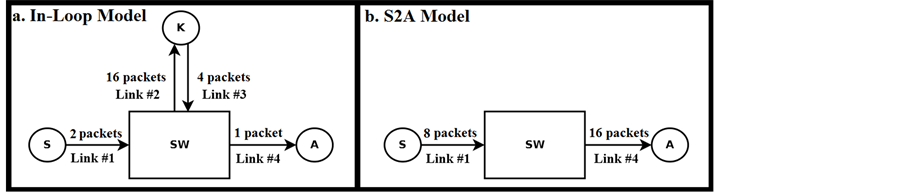
Figure 4. Worst-case packet flow analysis for the fault-free scenario.
On the other hand, upon the failure of one of the controllers in the in-loop model and the failure of one controller per actuator in the S2A model, the worst case packet flow analysis will be 22 for the in-loop model and 20 for the S2A model as in [30] . Therefore, the Dtotal calculations can be calculated using Equation (7) as shown below:
wang#title3_4:spIn-Loop Model
 (12)
(12)
 (13)
(13)
wang#title3_4:spS2A Model
 (14)
(14)
 (15)
(15)
A summary of the theoretical results for both in-loop and S2A models in fault-free and failed controller(s) scenarios is shown in Table 1.
4. Simulation Results
In this section, OMNET++ simulation results are presented. In all simulations, there were no packets dropped.
4.1. Fault-Free Scenario
OMNeT++ simulations are carried out for both fault-tolerant models: the in-loop based on the model in [10] and the S2A model based on the one in [30] . Using Fast Ethernet, the in-loop model had a smaller maximum end-toend delay of 305.470µs compared to 318.734 µs for the S2A model. Note that the 305.470 µs delay is the sum of the 239.055 µs (maximum sensor to controller end-to-end delay) and 66.415 µs (maximum controller to actuator end-to-end delay) for the in-loop model as shown in Figure 5 and Figure 6 where the data travels over two hops. Also, the 318.734 µs delay is that for the actuator node only in the S2A model as shown in Figure 7 where the data travels over one hop. Similarly, using Gigabit Ethernet, the maximum end-to-end delay was found to be 30.574 µs for the in-loop model and 31.886 µs for the proposed model. This means that the in-loop model performs better, which is expected, due to the fact that there are two separate controllers in the in-loop model while there are 8 controllers (2 controllers per actuator) in the S2A thus increasing the amount of traffic in the network which increases the experienced end-to-end delay. In the Figures, the x-axis represents the Simulation Time (seconds) and the y-axis shows the End-to-end Delay (seconds).
4.2. Scenario with the Failed Controller(s)
On the other hand, upon the failure of one of the two separate controllers in the in-loop model or one controller from each of the four pairs of integrated controllers in the S2A model, it was found that the S2A model performs better with less end-to-end delay. This is due to the fact that traffic sent in the in-loop model must go through additional intermediate hops via the controller. In the S2A model, only one hop is needed to transmit the traffic thus decreasing the experienced end-to-end delay. In the scenario with the failed controller(s), using Fast Ethernet, the S2A model had a smaller maximum end-to-end delay of 265.615 µs compared to 292.189 µs for the inloop model. Note that the 292.189 µs delay is the sum of the 225.77 µs (maximum sensor to controller end-to

Table 1. Worst-case end-to-end delay analysis results summary (in µ seconds).
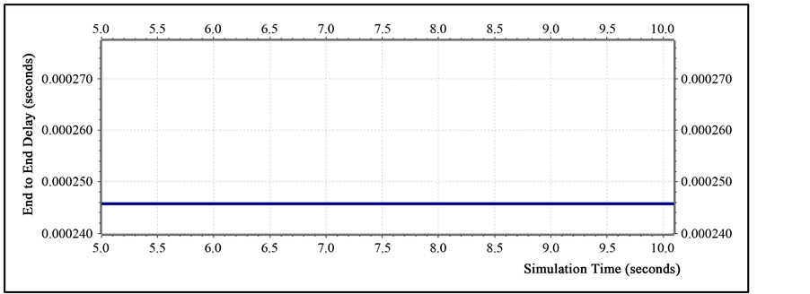
Figure 5. Constant maximum end-to-end delay between the 16 sensors and the controller (In-Loop Model).

Figure 6. Constant maximum end-to-end delay between the controller and the 4 actuators (In-Loop Model).

Figure 7. Constant maximum end-to-end delay between the 16 sensors and the 4 actuators (S2A Model).
end delay) and 66.419 µs (maximum controller to actuator end-to-end delay) for the in-loop model. Similarly, using Gigabit Ethernet, the maximum end-to-end delay was found to be 29.245 µs for the in-loop model and 26.575 µs for the S2A model. In conclusion, using both Fast and Gigabit Ethernet, the in-loop model showed less delay in the fault-free scenario while the S2A model showed less delay in the scenario with the failed controller(s) as summarized in Table 2 and Table 3. Also, Table 2 and Table 3 show the percentage error between calculated and simulated results. Note that, due to the regularity of the traffic imposed on the network, packets experience the same end-to-end delay for each sample.
Table 2. Theoritical and simulation results in fault-free scenario (in µ seconds).
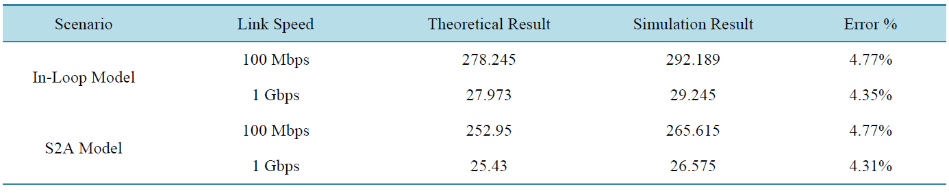
Table 3 . Theoritical and simulation results in scenario with the failed controller(s) (in µ seconds).
5. Conclusions
A major system design requirement for Networked Control Systems (NCSs) is to meet real-time delay requirement for sensors, controllers and actuators. Different protocols were studied to maintain requirements of speed and correctness such as Controller Area Network (CAN) and PROFlBUS. Ethernet in NCS is now one of the most widespread and low cost protocols available. Fault-tolerance techniques are required to increase reliability and lifetime of such networks. Therefore, in this paper, new models were studied on-top-of both Fast and Gigabit switched Ethernet. Comparison was made between the two proposed models via OMNeT++ simulations where the focus is on factors such as the packets dropped and the observed end-to-end delay. The delay measurement includes all types of encapsulation/decapsulation, propagation and queuing delays.
It was shown in the literature that the S2A model has a lower end-to-end delay than an in-loop controller model. In this paper, it was shown that both of the proposed architectures were successful in meeting all required timing constraints and no packets were dropped. However, the in-loop model performs better in terms of less total end-to-end delay than the S2A model in the fault-free situation because there are two separate controllers compared with 8 controllers (two controllers per actuator) in the S2A model thus increasing the delay. On the other hand, in the scenario with the failed controller(s), the S2A model was shown to have less total end-to-end delay. The traffic in the direct S2A model is sent over one hop compared to the in-loop model where the traffic must go through an additional intermediate hop via the controller thus increasing the experienced end-to-end delay. Different scenarios were tested including different link bandwidths (Fast or Gigabit Ethernet) in both the fault-free scenario and the scenario with the failed controller(s).