Experimental and numerical study of buoyancy driven flow within a bottom heated vertical concentric cylindrical enclosure ()
1. INTRODUCTION
The buoyancy flow in the cylindrical enclosures has been studied in the last couple of decades. Different parameters of interest have been investigated to dig out different hidden precious pearls out of the ocean of knowledge, but still leaving thrust of searching the new one. It has many engineering applications in the solar collectors, centrifuge machines, heat exchangers, materials processing, storage tanks, furnace designs and nuclear designs, etc.
The past researchers have conducted numerical study of buoyancy flow through different enclosures. The past authors [1-4] have numerically investigated the buoyancy effects within the cylindrical enclosures with thermophysical fluid properties assumed to be constant except density variation which varies according to Boussinesq approximation. Lemembre et al. have numerically investigated the two-dimensional laminar natural convection heat transfer in cylindrical enclosures of heated lateral walls at uniform heat flux and cooled at the same heat flux at the top surface by insulating the bottom surface [5]. The convection heat transfer was enhanced with the increase of aspect ratio and Rayleigh number. Chen et al. have numerically presented the two-dimensional steadystate laminar natural convection in the rectangular enclosures [6]. The flow and heat transfer in the enclosure were strongly affected by an asymmetric specification of the side wall temperatures. The asymmetry has induced a disproportionately higher increase in the Nusselt number of the hotter side wall relative to the decrease in Nusselt number of the colder wall.
Kee et al. have presented the experimental and numerical study of steady natural convection of a heat generating tritium gas in a two-dimensional closed vertical cylinders and spheres with their bounding isothermal walls [7]. They have demonstrated experimental and analytical agreement for the local temperatures over a range of Grashof numbers. References [8,9] have presented the experimental and numerical study of steady natural convection in two-dimensional Newtonian and incompressible fluid-filled enclosures. They have concluded that heat conduction has reduced the average temperature difference across the enclosure, produced partial stabilization of the flow and decreased natural convection heat transfer. The heat transfer and fluid flow leading to thermal stratification inside the enclosure were also studied. Bohn et al. have experimentally investigated the heat transfer between parallel and perpendicular vertical walls in a three-dimensional water-filled cubical enclosure with an adiabatic top and bottom and isothermal sides and discussed many aspects of natural convection flow [10].
Glakpe et al. have numerically investigated the laminar, three-dimensional natural convection in the air-filled vertical annular space formed by a square rod enclosed within a cylinder strongly affected by the Rayleigh number [11]. They have studied the effects of thermal radiation exchange between walls of an enclosure. Liaqat et al. have numerically analyzed laminar two-dimensional conjugate natural convection in an enclosure [12]. Their research has shown a significant change in the buoyancy flow parameters as compared to convectional investigations. Kuznetsov [13] has numerically investigated the two-dimensional conjugate convective-conductive heat transfer in a rectangular enclosure due to the local heat and contaminant sources and convective-radiative heat exchange with environment. The research work on the experimental study of conjugate heat transfer within a bottom heated vertical concentric cylindrical enclosure have been performed in Malik et al. [14].
In this research paper, the buoyancy effects within the vertical concentric cylindrical enclosure have been studied experimentally and numerically. The experimental results were measured at selected discrete points within the enclosure. Therefore, 2-D numerical simulations were performed using Fluent code to have a better understanding of the heat transfer and buoyancy effect, especially within the inner cylinder. The CFD results were validated using the experimental results of temperature along the wall of inner cylinder, already published in [14] and the new experimental axial temperature data along the axis of the enclosure. The numerical simulation results of streamlines of the each experiment were obtained to study buoyancy forces behavior due to change in the temperature of the bottom disc as well as the effects of thermal conductivities of the inner cylinder materials.
2. EXPERIMENTAL SETUP
In this research paper the CFD analysis of experimental work of the enclosure is performed to study the material effects of the disc and inner cylinder and diametric effects of the outer cylinder on the enclosure within the temperature range of 353 - 433. The experimental model used in this research work includes two vertical concentric cylinders with the inner shorter than the outer one, an electric heater, foundation box, temperature sensors, temperature controller, data acquisition system and a computer. Eighteen experiments are performed by changing the bottom disc temperature, inner cylinder material and outer cylinder diameter. The top as well as the bottom of the enclosure, except the bottom disc, are insulated with a layer of ceramic wool placed between two sheets of Teflon. N-type thermocouple is mounted to the upper central location of the disc. In the experiment 82 PT-100 type thermocouples are used. The uncertainty in the reading of N-type thermocouple is estimated to be less than 1.5% and that of PT-100 sensors less than 1.1%, including the effect of the scatter of observed experimental data as given in detail in Malik et al. [14].
3. MATHEMATICAL FORMULATION
Mathematical formulation of the buoyancy flow effects in the fluid-filled enclosures includes the governing equations of conservation of mass, momentum and energy to solve the flow domain. To deal with the conduction within the solids and radiations from hot surfaces their mathematical formulation must be added. In the subsequent articles a brief introduction of the equations necessary for solving conjugate heat transfer processes is given.
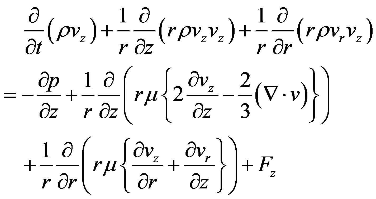
The Navier-Stokes governing equations in their differential form in 2-D cylindrical coordinate system (r, z) can be written as below:
 (1)
(1)
 (2)
(2)
 (3)
(3)
The stress tensor τ is given by:
 (4)
(4)
 (5)
(5)
These equations have been mentioned in detail in [15- 18].
Where, r = radial coordinate, z = axial coordinate, vr = radial velocity of the fluid, vz = axial velocity of the fluid, ρ = density of fluid, Sm = mass source term within the differential volume, p = static pressure, τ = stress tensor, g = acceleration due to gravity, F = external body forces including other model-dependent source terms such as porous medium and user-defined sources, μ = dynamic viscosity, I = unit tensor, keff = effective conductivity including the effect of turbulent thermal conductivity Jj = diffusion flux of species, and J. τeff = effective stress tensor, Sh = energy source term including radiation source, chemical reaction source etc.
The first three terms on the right side of Eq.5 give energy transfer due to conduction, species diffusion and viscous dissipation, respectively. The buoyancy forces can be designated by the ratio of Grashof and Reynolds numbers as shown below:
 (6)
(6)
There are strong buoyancy effects on the fluid flow when the above number approaches or exceeds unity. The strength of the buoyancy-induced flow in the pure natural convection is measured by the Rayleigh number;
 (7)
(7)
where, β = coefficient of thermal expansion and α = thermal diffusivity.
 (8)
(8)
A buoyancy-induced laminar flow is assumed at Ra < 108 and transition from laminar to turbulence is assumed in the range of 108 < Ra < 1010.
According to the Boussinesq approximation the density of the fluid is given by:
 (9)
(9)
where, ρo = constant density of the fluid in the closed domain, To = operating temperature and β = coefficient of thermal expansion.
Fourth term of the energy equation (Eq.5) (Sh) also includes the heat source due to radiation. Rosseland radiation model is used which is faster and requires less memory as compared to other radiation models and deals with axisymmetric geometries and contains the effect of scattering. The radiative heat flux equation, the equation becomes;
 (10)
(10)
Both the specific radiative (qr) and specific conduction heat fluxes (qc) have the same form, therefore, these can be written as,
 (11)
(11)
where, k is the thermal conductivity, kr is the radiative conductivity.
3.1. Boundary Conditions
In this research work the experimental model used is the vertical concentric cylindrical enclosure as shown in Figure 1. The mathematical formulation of these boundary conditions is given below.
3.1.1. Bottom Disc Wall Boundary
Heat source is applied at the bottom of the disc of radius, r1. The temperatures are specified for different experiments at z = 0 and known. Its boundary conditions are;
At 
T is known;  (No slip condition).
3.1.2. Bottom Insulated Wall Boundary
Bottom surface of enclosure is assumed to be insulated except bottom disc heated by the heat source. Its boundary conditions are:
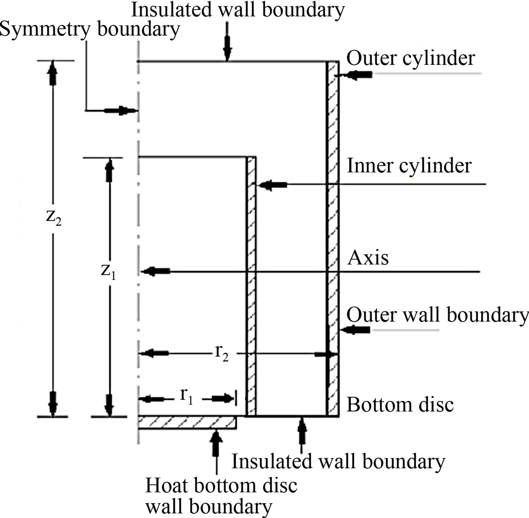
Figure 1. Boundary conditions of vertical concentric cylindrical enclosure.
At ;
;
 (No slip condition);
  for an adiabatic wall.
3.1.3. Side Wall Boundary
Natural convection heat transfer coefficient ho is taken as a boundary of enclosure. Heat entering from the hot bottom disc after passing through the walls of inner cylinder comes out of the wall of outer cylinder of enclosure. Its boundary conditions are: at 
3.1.4. Symmetry Boundary
In 2-D axisymmetric geometry the axis is used as a symmetry boundary and half of the geometry is taken for the analysis as shown in Figure 1 as used by the past researchers [19-21]. Its boundary conditions are:
at 
 .
.
3.1.5. Top Insulated Wall Boundary
Top wall of enclosure is taken as insulated or adiabatic one. Its boundary conditions are;
At 
 (No slip condition);
 .
.
4. NUMERICAL SIMULATIONS
In this research paper the experimental and numerical study of the heat transfer and buoyancy driven flow along axis of the enclosure is studied. The numerical simulations of inner cylinder of the enclosure are performed validating the experimental results of Malik et al. [14] the chemical processes take place within the inner cylinder of the enclosure and main concentration of the chemical reactions is along axis of the enclosure. The numerical simulations are validated by comparing with experimental results and presented streamlines of the each experiment clearly depicting the real picture of the of the enclosure showing buoyancy forces due to change in the temperature range of the bottom disc.
This research study provided a thorough insight of the buoyancy flow and its effects due to the change of inner cylinder wall material in the enclosure and outer cylinder diameter. FLUENT 6.3 software is used to study the buoyancy forces within the enclosure, compare and validate numerical results with the experimental ones and get insight of the flow and heat transfer mechanism within the enclosure as used by the past researchers [9,19,22].
Two-dimensional steady state analysis is carried out. The Rosseland radiation model is selected. Air is treated as a stationary, incompressible and laminar fluid. The FLUENT have used the pressure-based solver. The second order scheme is used for pressure, while the second order upwind discretization schemes are used for momentum and energy [23]. The flow and energy equations are solved by the FLUENT [15] and the Green-Gauss cell-based gradient scheme is selected. Boussinesq approximation is used. In order to solve the pressure-velocity coupling SIMPLE algorithm is used [1,4,24-28]. The convergence criteria are different for different cases [29-31]. Iterations took place till the convergence is achieved in the range of 765 - 4968 iterations. Eighteen experiments are performed at the specific temperatures of 353, 393 and 433 K on the upper central location of bottom discs. The mesh selected is square and total cells of both configurations (O1 and O2) are 213,960 and 247,400 respectively.
4.1. Geometry and Meshing
In this research work the geometry considered for analysis is a two-dimensional axisymmetric one due to which the axis is used as a symmetry boundary. The half of the geometry is taken for the analysis due to its axisymmetric geometry [19-21]. Gambit 2.3.16 is used as a preprocessor to construct the geometry and mesh.
The geometry is generated and meshed in the Gambit software as shown in the Figure 2. Square mesh is used

Figure 2. Meshing of enclosure, (a) Bottom; and (b) Top geometries of outer cylinder.
to mesh the geometry. The grid points along the axis of the geometry are 1541 while at its top and bottom are 211. Due to change in diameters of the radial grid points are 139 and 151 for outer cylinders, O1 and O2 respectively.
The buoyancy flow about the geometry axis is assumed to be symmetric. 2-D axisymmetric simulations are carried out. The bottom disc of the enclosure being simulated has been shown in the Figure 1. Top and bottom walls of the enclosure except the bottom disc are assumed to be adiabatic with no heat flux and no heat generation with no slip condition on the enclosure walls. The walls within the enclosure are thermally coupled. The convection heat transfer coefficient, h is selected as a boundary condition at the outer surface of the outer vertical cylinder by hit and trial method.
The inner and outer cylinders walls are considered as conducting walls. The user defined function has incurporated the experimental temperature results of bottom disc and coupled with the FLUENT [15]. The three inner cylinders of aluminum, mild-steel and stainless-steel having similar dimensions are used in different configurations.
The outer surface of the simulated enclosure is far away from heat source, it was assumed that the pressure and temperature at the outer surface of the enclosure are equal to the ambient to allow free movement across this surface. There is an ambient temperature at the top of the vertical enclosure, so the enclosure was assumed as an infinite enclosure. The properties of fluid and materials used in these simulations are given in the Tables 1 and 2 respectively as taken from research paper [32].
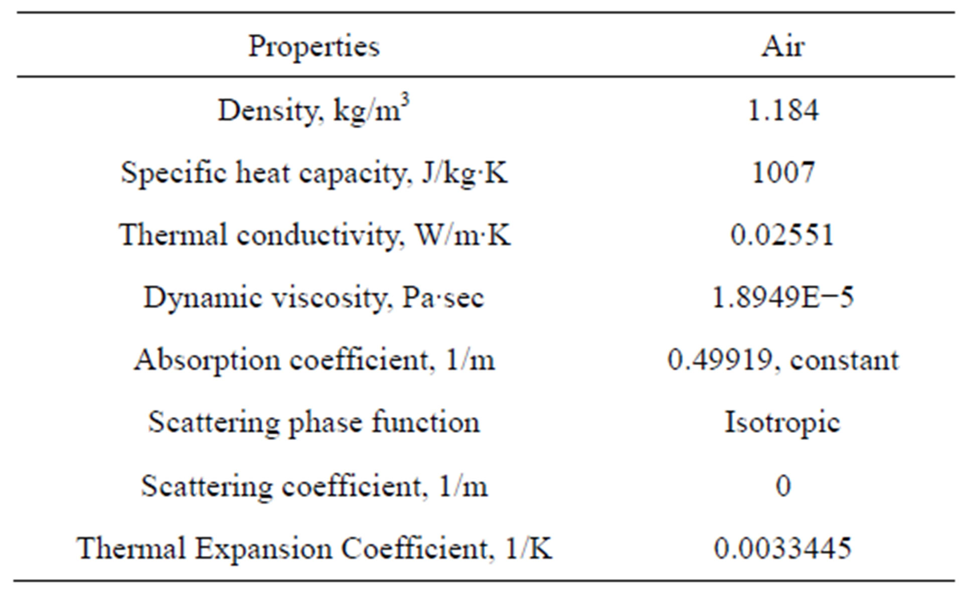
Table 1. Properties of Fluid (air).
4.2. Grid Independence Study
The grid independence study is carried out by taking the grids of cell sizes 2 mm, 1.5 mm, 1mm and 0.5 mm as shown in the Table 3. There is a prominent percentage error of cell sizes 2 mm, 1.5 mm and 1mm, while cell sizes 1mm and 0.5 mm have almost the same percentage error with the experimental results of the axis of the enclosure Malik et al. [14]. Therefore, cell size of 1 mm is taken while meshing the enclosure under research. The numerical simulations results are compared with the experimental results.
5. RESULTS AND DISCUSSION
Before discussing numerical results an effort was made to validate the numerical simulations. The experimental data of eighteen different experiments was used to validate the numerical results. Three different inner cylinders made of aluminum, mild steel and stainless steel and two outer cylinder diameters have been used in the experiments. The comparison between experimental and numerical simulation results of temperature within enclosure configurations with inner cylinders of aluminum, mild steel and stainless steel at different bottom disc central temperatures (353, 393 and 433 K) is shown in Figure 3. The positive and negative errors of numerical simulation results with the experimental ones are 1% and 1.3% respectively. This shows that numerical simulation results are in best agreement with experimental ones.
5.1. Temperature Profile along the Enclosure Axis
The heat transfer mechanism within the inner cylinder has a strong effect on the process of segregation of chemicals taking place here. The temperature behavior at the wall of inner cylinder using experimental data for the same geometry has been studied previously by Malik et al. [14], however, the experimental temperature data along the axis of the inner cylinder and the numerical results of streamlines within the enclosure have been presented in this paper to study the buoyancy effects. The comparison of experimental and numerical axial temperature distribution along the axis of vertical concentric cylindrical enclosure under different operating conditions is shown in Figure 4. The experimental results of axial temperature match closely with the numerical simulation results and thus validating the numerical simulations. The aspect ratio and radius ratio of the enclosure geometry with outer cylinder O1 are 6.016 and 1.73, while with outer cylinder O2 these values are 5.133 and 2.055 respectively.
The axial temperature distribution using aluminum inner cylinder is almost independent of the outer cylinder diameter as shown in the Figures 4(a) and (b), however,
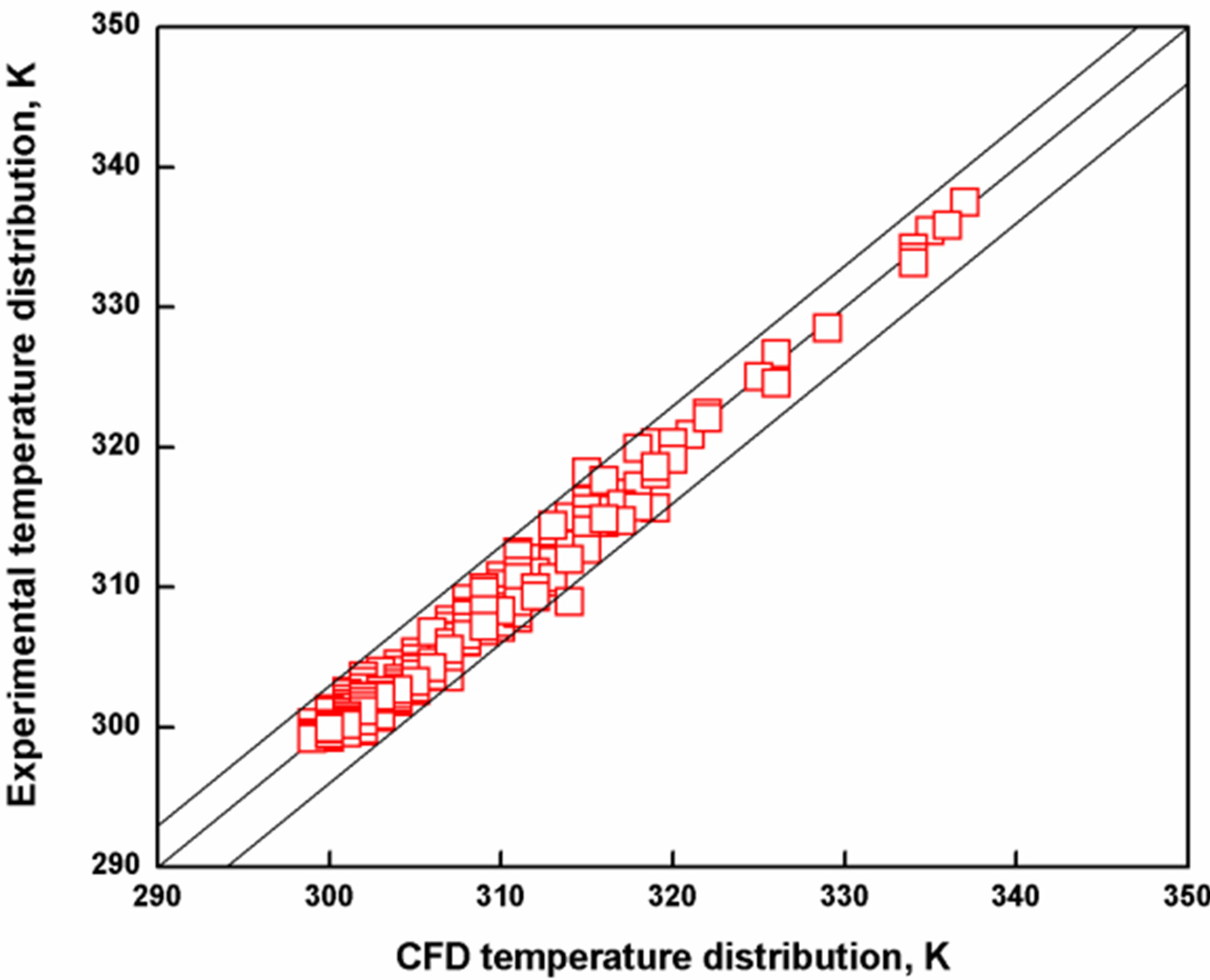
Figure 3. Comparison of experimental and CFD results of enclosure with inner cylinders of aluminum, mild steel and stainless steel.

Figure 4. Axial temperature distribution along the axis of the enclosure with inner cylinder of (a, b) aluminum; (c, d) mild steel and (e, f) stainless steel.
Figures 4(c)-(f) show that the axial temperature distribution using mild steel and stainless steel inner cylinders is a function of the outer cylinder diameter especially at higher temperatures of the bottom disc. This response might be due to high thermal conductivity of aluminum as compared to mild steel and stainless steel.
5.2. Temperature Profile along the Inner Cylinder
As mentioned before the experimental temperature data along the wall of inner cylinder has been published previously [14], however, this data is used in this work to validate the numerical results. The comparison of experimental and numerical axial temperature distribution along the wall of inner cylinder under different operating conditions is shown in Figure 5.
It is observed in Figures 5(a) and (b) that using inner cylinder of aluminum material, under different temperatures of the bottom disc and using two different outer cylinders O1 and O2. Figures 5(c)-(f) show the same results using inner cylinders of mild steel and stainless steel respectively. It is observed in Figures 5(a) and (b) that using inner cylinder of aluminum the axial temperature distribution along the inner cylinder is independent of the outer cylinder diameter, while using inner cylinders of mild steel and stainless steel (Figures 5(c)-(f)) the axial temperature along the inner cylinder depends on the diameter of outer cylinder.
The close agreement between the experimental and numerical results of axial temperature along inner cylinder supports the numerical simulation of vertical concentric cylindrical enclosure. By comparing the Figures 4 and 5 along the axis and the inner surface of inner cylinder of the enclosure respectively it is observed that the temperatures along the axis are slightly higher than along the wall of the inner cylinder at the same axial location. This temperature gradient boosts the buoyancy effect and therefore helps the segregation of chemicals as well as transfer of heat out of the inner cylinder.
5.3. Buoyancy Effect in the Enclosure
When an object is partially or fully immersed in a fluid the upward force exerted on the object is called buoyancy force. The value of this buoyancy force is equal to the weight of the fluid displaced by the object. The fluid density varies with temperature by the addition of heat to a fluid and flow is induced by the gravitational force acting on the density variations called natural convection flows. The streamlines clearly depict the buoyancy effects in the enclosure with the change of inner cylinder material and outer cylinder diameter at bottom disc temperature range of 353 - 433 K.

Figure 5. Axial temperature along the inner surface of inner cylinder of (a, b) aluminum, (c, d) mild steel and (e, f) stainless steel.
5.3.1. Contours of Streamlines at 353 K
The contours of streamlines are obtained from numerical simulations for the enclosure configurations O1 and O2 at bottom disc central temperature of 353 K and are shown in Figure 6. Figures 6(a) and (b) show streamlines for two configurations (O1, O2) of aluminum inner cylinder, while Figures 6(c)-(f) show the corresponding results for mild steel and stainless steel inner cylinders.
It was observed in Figures 6(a) and (b) that the streamlines within the inner cylinder are same for both configurations (O1, O2) of aluminum inner cylinder. The same behavior was observed in case of mild steel (Figures 6(c) and (d)) and stainless steel inner cylinders (Figures 6(e) and (f)). However, the streamlines in the inner cylinder of Figures 6(a) and (b) show weak buoyancy effects as compared to Figures 6(c)-(f). Another important observation made regarding Figure 6 is that the buoyancy effects are stronger in the outer annulus with outer cylinder configuration O2 as compared to configuration O1 for all three inner cylinders used. The buoyancy effects in the outer annulus are stronger in case of aluminum inner cylinder as compared to mild steel and stainless steel for the same outer configuration. The same behavior was observed in case of mild steel inner cylinder as compared to stainless steel.
At the bottom disc central temperature of 353 K the quantity of heat transfer added to the enclosure is small and therefore the effect of outer cylinder configuration on the heat transfer from the inner cylinder to the outer annulus region is negligible. However, due to difference of thermal conductivity buoyancy effects are relatively weak in Figures 6(a) and (b) as compared to Figures 6(c)-(f). With outer cylinder configuration O2 the buoyancy effects are stronger due to increase in volume as compared to configuration O1 for three inner cylinders used. In the outer annulus the buoyancy effects are stronger while using inner cylinder of aluminum as compared to other inner cylinders due to its high thermal conductivity.
5.3.2. Contours of Streamlines at 393 K
The contours of streamlines are obtained from numerical simulations for the enclosure configurations O1 and O2 at bottom disc central temperature of 393 K and are shown in Figure 7. Figures 7(a) and (b) show streamlines for two configurations (O1, O2) of aluminum inner cylinder. Similarly Figures 7(c)-(f) show the corresponding results for mild steel and stainless steel inner cylinders. It is observed in Figures 7(a) and (b) that the streamlines within the inner cylinder are same for both configurations (O1, O2) of aluminum inner cylinder. The same behavior is observed in case of mild steel and stainless steel inner cylinders (Figures 7(c)-(f)), but the streamlines in the inner cylinder of Figures 7(a) and (b) show weak buoyancy effects as compared to Figures 7 (c)-(f).

Figure 6. Streamlines of enclosure for configuration O1 (a) aluminum inner cylinder, (c). mild steel inner cylinder, (e) stainless steel inner cylinder, for configuration O2 (b) aluminum inner cylinder, mild steel inner cylinder, (f), stainless steel inner cylinder at 353 K.
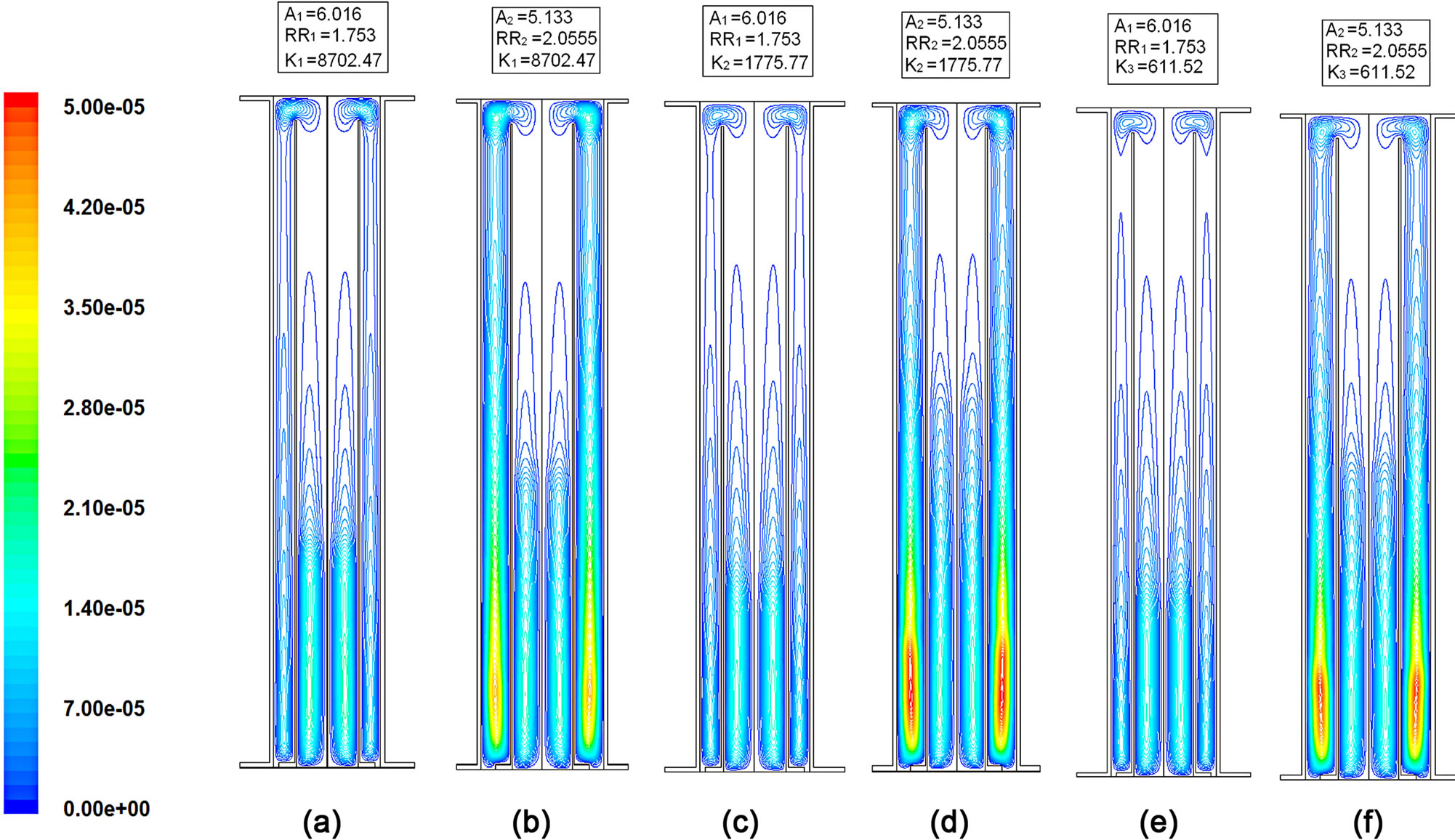
Figure 7. Streamlines of enclosure for configuration O1 (a) aluminum inner cylinder, (c). mild steel inner cylinder, (e) stainless steel inner cylinder, for configuration O2 (b) aluminum inner cylinder, mild steel inner cylinder, (f), stainless steel inner cylinder at 393 K.
The buoyancy effects are stronger in the outer annulus with outer cylinder configuration O2 as compared to configuration O1 for all three inner cylinders used. The buoyancy effects in the outer annulus are stronger in case of aluminum inner cylinder as compared to mild steel and stainless steel for the same outer configuration. The same behavior is observed in case of mild steel inner cylinder as compared to stainless steel.
Like 353 K at the bottom disc central temperature of 393 K the quantity of heat added to the enclosure is small due to which the heat transfer on outer annulus region with the increase of outer cylinder diameter is negligible. Contours of streamlines are at 433 K.
However, due to difference of thermal conductivity buoyancy effects are relatively weak in Figures 7(a) and (b) as compared to Figures 7(c)-(f). With outer cylinder configuration O2 the buoyancy effects are stronger due to increase in volume as compared to configuration O1 for three inner cylinders used. In the outer annulus the buoyancy effects are stronger while using inner cylinder of aluminum as compared to other inner cylinders due to its high thermal conductivity.
The contours of streamlines are obtained from numerical simulations for the enclosure configurations O1 and O2 at bottom disc central temperature of 433 K and are shown in Figure 8. Figures 8(a) and (b) show streamlines for two configurations (O1, O2) of aluminum inner cylinder, while Figures 8(c)-(f) show the corresponding results for mild steel and stainless steel inner cylinders. It is observed in Figures 8(a) and (b) that at bottom disc temperature of 433 K the streamlines behavior within the inner cylinder changes with outer cylinder configuration for aluminum inner cylinder. Similarly the same behavior is observed for mild steel and stainless steel inner cylinders (Figures 8(c)-(f)). The most remarkable observation made regarding Figure 8 is that the buoyancy effects are stronger in the outer annulus with configuration O2 as compared to configuration O1 for all three inner cylinders used. The buoyancy effects in the outer annulus are stronger in case of aluminum inner cylinder as compared to mild steel and stainless steel for the same outer configuration.
The same behavior is observed in case of mild steel inner cylinder as compared to stainless steel. At high bottom disc central temperature of 433 K the outer cylinder diameter also affects the heat transfer mechanism within the inner cylinder due to higher heat transfer rates through the enclosure. Figure 9 shows the enlarged view of streamlines in configuration O2 for different materials of the inner cylinder of the inner cylinder for bottom disc temperature of 433 K. In the enclosure with aluminum inner cylinder (Figure 9(a)) the heat is transferred axially as well as radially from the bottom disc at 433 K. The streamlines at the top of the aluminum inner cylinder forming a loop on its tip enters the outer annulus, while at the same time the heat is also transferred radially

Figure 8. Streamlines of enclosure for configuration O1 (a) aluminum inner cylinder, (c) mild steel inner cylinder, (e) stainless steel inner cylinder, for configuration O2 (b) aluminum inner cylinder, mild steel inner cylinder, (f) stainless steel inner cylinder at 433 K.
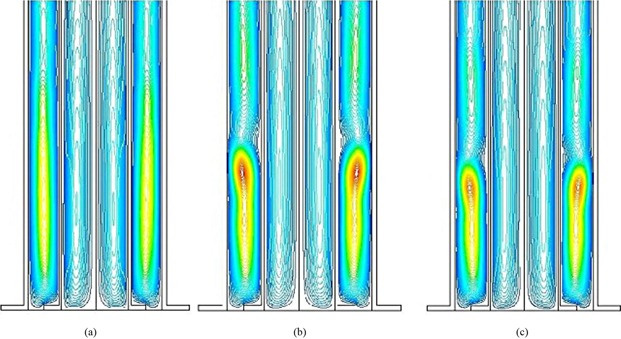
Figure 9. Streamlines of lower half of the enclosure for configuration O2 (a) aluminum inner cylinder, (b) mild steel inner cylinder, (c) stainless steel inner cylinder at 433 K.
through the wall of the aluminum inner cylinder forming one axially dominant thermo-siphoning in the outer annulus as shown in the Figure 9(a). For the mild steel and stainless steel inner cylinders more heat is transferred through axial direction than in the radial ones forming ultimately two thermo-siphonings in the outer annulus of the enclosure with the lower one as radially dominant and upper one as axially dominant as shown in the Figures 9(b) and (c).
Due to high thermal conductivity of aluminum, the buoyancy effects within the inner cylinder are less and more heat is transferred through the wall of aluminum inner cylinder than mild steel and stainless steel ones forming one axially dominant thermo-siphoning in the outer annulus as shown in the Figure 9(a). While, due to low thermal conductivities of mild steel and stainless steel buoyancy effects are more and walls of the inner cylinders are at higher temperatures than the walls of the aluminum inner cylinder as shown in the Malik et al. [14]. Therefore, in their outer annuli there are two thermosiphonings with the lower one as radially dominant and upper one as axially dominant as shown in the Figures 9(b) and (c).
In the outer annulus the buoyancy effects are stronger while using inner cylinder of aluminum as compared to other inner cylinders due to its high thermal conductivity. The stream lines in Figures 6-9 also suggest that due to high thermal conductivity of aluminum inner cylinder, the heat conduction in inner cylinder wall in the axial direction is high as compared to inner cylinders of mild steel and stainless steel. This behavior is more clearly visible in Figure 9, where due to low thermal conductivity of mild steel and stainless steel double vortices are formed in the outer annulus region with outer cylinder configuration O2 (Figures 9(b) and (c)). Apart from the above discussion there are other numerous points which can be highlighted using the numerical simulation results.
6. CONCLUSIONS
In this research paper, experimental and numerical study of the axial temperature gradient, buoyancy driven flow and the heat transfer mechanism within the enclosure were performed. The numerical simulations were validated by comparing the numerical results with experimentally measured axial temperature. The numerical results of the streamlines within the enclosure depicted the real picture of the buoyancy effects. Eighteen different experiments were performed in a controlled environment. The axial thermal behavior along the axis and inner cylinder of the enclosure were studied by varying bottom disc central temperature (353 - 433 K), inner cylinder material and outer cylinder diameter. The main focus of this study was given on the thermal behavior and buoyancy effects of the enclosure by using three inner cylinders of different materials and having large difference in their thermal conductivities. The numerical simulations were performed and validated by the experimental results. The heat transfer and buoyancy effects within the enclosure geometry were highlighted through streamlines obtained from numerical simulations. As a result of these experiments and numerical simulations, following points were concluded;
1) The heat transfer in the enclosure with stainless steel inner cylinder was more sensitive to outer cylinder diameter as compared to mild steel. In this case, thermal conductivity and the outer cylinder diameter were both the controlling parameters for the heat transfer mechanism. Aluminum was non-sensitive to the outer cylinder diameters (O1, O2).
At the bottom disc temperature of 353 K and 393 K, the streamlines within the inner cylinder were almost same for both configurations (O1, O2) of three inner cylinders of aluminum, mild steel and stainless steel being independent of outer diameter used, but clear changes were being observed at 433 K.
2) With outer cylinder configuration O2 the buoyancy effects were stronger due to increase in volume as compared to configuration O1 for three inner cylinders used.
3) In the outer annulus, the buoyancy effects were stronger while using inner cylinder of aluminum as compared to other inner cylinders due to its high thermal conductivity.
One axially dominant thermo-siphoning was formed in the outer annulus due to high thermal conductivity of aluminum inner cylinder, while two thermo-siphonings were formed in the outer annuli with the lower one as radially dominant and upper one as axially dominant due to their low thermal conductivities of mild steel and stainless steel inner cylinders.