Strontium and Silicon Co-Doped Apatite Coating: Preparation and Function as Vehicles for Ion Delivery ()
1. Introduction
Hydroxyapatite (HA) is widely used as a coating to improve the bone-bonding of permanent implants for biomedical applications such as hip prostheses [1,2]. By improving the bond between the implant and bone the risk of revision surgery can be reduced [3,4]. Previously, HA prepared with a mineralization method has been coloaded with bisphosphonates and antibiotics, with the purpose of promoting bone formation around the implant site and reducing the risk of infections [5]. However, the introduction of pharmaceutical agents significantly adds to the complexity of implants, both from a manufacturing, handling and regulatory point of view. Biologically active ions could be used as alternative approach to overcome some of these drawbacks. Studies have shown that ion doped HA, i.e. hydroxyapatite containing foreign ions, is a promising way to improve the cell proliferation and in vivo bone tissue response without the addition of pharmaceutical agents [6-8]. Compared to pure HA, these modified HA have different solubility, crystallinity and topography, all of which are factors that are expected to influence the bone response around the implant [9].
Bone consists of cells, collagen fibers and hydroxyapatite, the latter containing traces of Sr2+, Si4+ and F– in the HA-lattice [10,11]. Strontium has been shown to enhance the bone formation in vitro and in vivo [12], and the incorporation of silicon into the apatite structure was found to result in a biomaterial with improved osseointegration properties compared to pure hydroxyapatite [6]. A silicon doped hydroxyapatite coating prepared with a mineralization method on porous titanium substrate has also been tested in vivo with promising results [13]. The (in vivo) results showed that the bone ingrowth rate (BIR) was significantly higher for silicondoped HA (Si-HA) coating than for the pure HA [13]. In view of these observations, a simultaneous delivery of multiple ion species from an implant coating in vivo could help to induce bone formation and also reduce bone resorption. It could therefore be possible to combine these effects by co-doping strontium and silicon into the hydroxyapatite coatings. The preparation of co-doped hydroxyapatite ceramics, mostly based on powder techniques, has previously been reported [14-17]. Some work has also been reported on preparation of Sr or Si containing hydroxyapatite coatings by a mineralization method [7,18-20].
The aim of this work was to prepare apatite coatings containing both Sr and Si on pre-treated titanium surfaces for biomedical applications. The coating could act as a system for simultaneous delivery of Sr and Si ions, thus combining the biological effects of these ions. In order to establish process-property relationships, the effects of soaking medium, ion concentration in the soaking medium and soaking temperature on the morphology and composition of the coatings were investigated.
2. Materials and Methods
2.1. Materials
Titanium plates, size 10 mm × 10 mm, were cut from grade 2, 1 mm thick sheet of titanium metal (Edstraco AB Sweden). The plates were oxidized in air at 800˚C for 1 h with a ramp rate of 5˚C/min to form a titanium dioxide surface. The plates were then treated in an alkaline solution (5 M NaOH) for 1 h in an ultrasonic bath. Afterwards the plates were ultrasonically treated in successive baths of ethanol (15 min) and water (15 min) at 37˚C before use.
2.2. Preparation of Sr and Si Co-Doped Apatite Coatings
The Sr and Si containing apatite coatings were prepared by a mineralization process. A modified solution of Dulbecco’s phosphate buffer saline (PBS, Aldrich) was used as solution medium. Strontium nitrate was used as the source of Sr ions and sodium silicate was used as the Si ion source. PBS solution with different concentrations of Sr and Si were prepared, see Table 1.
The heat-treated titanium plates were placed in sealed plastic bottles containing Sr-Si-PBS solutions at 37˚C or 60˚C for 2 weeks. The solution was exchanged after 1 week to avoid significant ion depletion in the solution. After completed soaking, the plates were gently rinsed in deionised water and dried at 37˚C before further analysis.
2.3. Characterization of Sr and Si Co-Doped Apatite Coatings
The coatings were analyzed by X-ray diffraction (XRD) (Siemens diffractometer D5000). The diffractometer was operated at 45 kV and 40 mA at a 2θ range of 20˚ - 60˚. The incidence angle was fixed at 2˚.
The morphology of the coatings was investigated using field emission scanning electron microscopy (FESEM, LEO1550). Before the SEM analysis, the samples were coated with a thin film of gold, using ion sputtering. SEM images were acquired at different magnifications, using the in-lens detector and an acceleration voltage of 3 kV. Inductively coupled plasma-optical emission spectroscopy (ICP-OES) was used for analyzing the composition and the ion release from the co-doped Sr and Si apatite coating (see below).
2.4. Ion Release from Sr and Si Co-Doped Apatite Coatings
In order to study the stability and ion release characteristics, the release of Sr and Si ions into solutions of Tris-HCl and PBS was measured for one selected coating, 015Sr2Si-PBS prepared at 60˚C for 2 weeks. This selected coating has the highest Sr/Ca and Si/P ratios according to ICP-OES analysis. The Sr and Si containing apatite coating was prepared as described above, with the exception that the PBS solution was exchanged every 3 days. The coated samples were immersed in 10 ml of Tris-HCl or PBS solution (5 mL/plate), in closed plastic bottles, for periods up to 14 days. The ion release experiment was performed in static mode using the following protocol. At time points 3 hours, 1 day, 3 days, 5 days, 8 days and 14 days, 2 mL solution was withdrawn from the solution and stored in centrifuge tubes prior to analysis by ICP-OES. 2 mL fresh solution was added to maintain a constant volume of solution.
2.5. Mechanism of Ion Release from the Coatings
Korsmeyer-Peppas model (Equation (1)):
 (1)
(1)
was used to analyse the measured ion release data in order to evaluate the mechanism of release from the codoped Sr and Si apatite coatings. In this model, F is the fraction of ion release after time t, Qt is the amount of

Table 1. Ion concentration in Dulbecco’s PBS and Sr-Si-PBS (10−3 M).
substance released after time t, Q is the total amount of substance, k is the kinetic constant, n the diffusion release constant which is characteristic of the release mechanism and t is the time in hours [21]. Using this model different ion kinetic values (n) were calculated. To evaluate the release mechanism an n value of 0.5 was used. We assume that the apatite particles are plate-like, and according to the paper by Ritger and Peppas [19], Fickian diffusion has a limited value of n = 0.5 for slabs. Values of n < 0.5 means the release is controlled mainly by a quasi-Fickian diffusion mechanism. If the n value is between 0.5 and 1 the release of ions from the coatings is a combination of Fickian diffusion and dissolution of the coating [22]. These values can be used to assess which mechanism is controlling the release of ions from the co-doped Sr and Si apatite coating.
3. Results
3.1. SEM Analysis
The morphology of samples formed in the different solutions at a given temperature show similar morphologies, see Figures 1 and 2.
However, the coatings formed at different tempera-

Figure 1. Morphology of the Sr and Si co-doped apatite coatings. The heat treated surfaces were soaked for 2 weeks with: (A) and (B) 0.06 mM Sr and 1 mM Si at 37˚C; (C) and (D) 0.15 mM Sr and 1 mM Si at 37˚C; (E) and (F) 0.06 mM Sr and 1 mM Si-PBS at 60˚C; (G) and (H) 0.15 mM Sr and 1 mM Si at 60˚C.

Figure 2. Morphology of the Sr and Si co-doped apatite coatings. The heat treated surfaces were soaked for 2 weeks with: (A) and (B) 0.06 mM Sr and 2 mM Si at 37˚C; (C) and (D) 0.15 mM Sr and 2 mM Si at 37˚C; (E) and (F) 0.06 mM Sr and 2 mM Si-PBS at 60˚C; (G) and (H) 0.15 mM Sr and 2 mM Si at 60˚C.
tures showed clear differences. Coatings formed at 37˚C show an underlying relative uniform coating, which was partially covered by the sphere-like particles (typical size 3 - 5 µm). Both the underlying layer and the spheres had flake-like morphology in the submicron scale. For the coatings formed at 60˚C, the morphology was completely dominated by partially fused or interlocked sphere-like particles. The size of the particles was typically 1 - 2 µm. The size of the particles was larger for the coatings prepared at 37˚C compared to those at 60˚C, see Figures 1 and 2.
3.2. X-Ray Diffraction (XRD) Analysis
All the co-doped Sr and Si apatite coatings showed peaks of apatite (hydroxyapatite, PDF No. 09-0432) after soaking at 37˚C and 60˚C for 2 weeks, see Figure 3.
The peak at around 26˚ is related to plane (002). The peak at around 31˚ was broad and could be the overlapping of the planes (211), (112), (300). In addition two peaks were detected around 46˚ which corresponds to plane (222) and 49˚ which was related to plane (213). The relatively broad apatite peaks indicate that the


Figure 3. XRD patterns of coatings prepared for 2 weeks in D-PBS with different concentrations and soaking temperature: (a) 2 mM Si; (b) 1 mM Si (R: rutile; A: apatite).
coating were poorly crystalline. It can also be observed that the intensity of peaks corresponding to apatite were stronger at 60˚C than 37˚C, most likely this was due to higher thickness.
3.3. ICP-OES Analysis
In the ICP-OES analysis, Ca, Mg, P, Sr and Si were detected in all coatings. The Ca/P and (Ca + Sr)/(Si + P) ratios were between 1.2 - 1.4 and 1.1 - 1.2, respectively (Figures 4(a) and (b)).
These ratios are much lower than for stoichiometric HA, 1.67 which indicates that the coatings are calcium deficient. This is also in agreement with previous results on single ion co-doped calcium phosphate films [16]. It can be observed that there was a difference between the Ca/P ratio and the (Ca + Sr)/(Si + P) ratios; taking into account of the addition of Sr and Si ions decreased the ratio somewhat (see Figures 4(a) and (b)). The soaking temperature and ion concentrations of Sr and Si in the solution did not significantly affect the Ca/P or the (Ca + Sr)/(Si + P) ratios. However the Sr/Ca ratios showed an increase with increasing Sr concentration in the medium and with increasing soaking temperature, see Figures 4(c) and (d). The same trend was observed for the Si/P ratio.

Figure 4. (a), (b): Ca/P and (Ca + Sr)/(Si + P) ratios; (c), (d): Sr/Ca and Si/P ratios for SrSiHA obtained by ICP-OES analysis.
The Si/P ratios were higher than the Sr/Ca indicating that the silicon content in the coating was higher than that of Sr.
3.4. Ion Release
The ion release results show that it was possible to release both Sr and Si from the co-doped Sr and Si apatite coating. The ICP analyses revealed that release of Ca, Mg, Sr and Si occurred in both PBS and Tris-HCl. The release profiles (ion concentration in solution vs. immersion time) were different in Tris-HCl compared to the PBS solution that contains Ca and Mg ions, see Figures 5(a) and (b).
In Tris-HCl there was a continuous sustained release of Ca, Mg, Sr and Si. The release of Si was higher than the release of Sr. SEM images, Figure 5, of the co-substituted Sr and Si apatite coating before and after release in Tris-HCl showed similar morphology.
In PBS there was an initial drop observed during the first 24 h, after which the Ca concentration slowly increased and the stabilized. For Mg there was a slow decrease indicating precipitation. Both Sr and Si showed a continuous sustained release. The release of Si was higher than for Sr in PBS. After ion release in PBS newly
 (a)
(a) (b)
(b)
Figure 5. Ion release curves for 015Sr2SiHA coating in (a) Tris-HCl and (b) PBS.
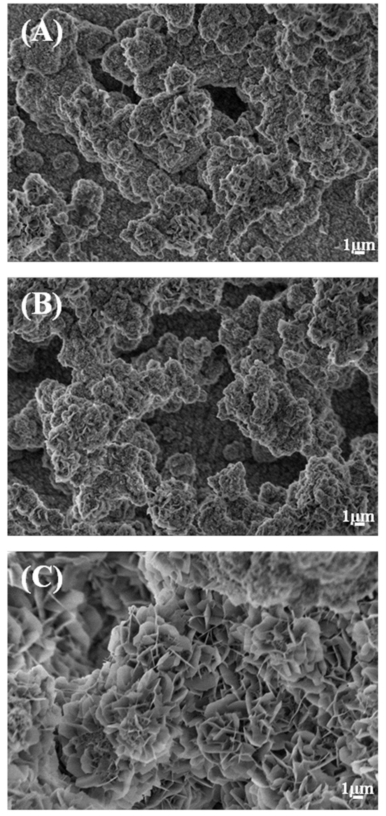
Figure 6. Morphology of 015Sr2SiHA coating before release (A), and after ion release in Tris-HCl (B) and PBS (C).

Figure 7. Korsmeyer-peppas plot for 015Sr2SiHA after ion release in Tris-HCl.
formed apatite was observed on the surface, Figure 6.
Figure 7 shows Korsmeyer-Peppas plots for the release data. The ion kinetic values (n), summarized in Table 2, showed that the release of ions in Tris-HCl (nCa = 0.53, nMg = 0.57, nP = 0.60, nSr = 0.56, nSi = 0.61) were a combination of Fickian diffusion and dissolution of the coatings. The obtained R2 values > 0.98 show that the K-P model fits well for describing the ion release