Engineering
Vol. 4 No. 9 (2012) , Article ID: 23245 , 4 pages DOI:10.4236/eng.2012.49073
An Ancient Rangefinder for Teaching Surveying Methods
Department of Applied Science and Technology, Politecnico di Torino, Torino, Italy
Email: amelia.sparavigna@polito.it
Received June 8, 2012; revised July 7, 2012; accepted July 18, 2012
Keywords: Telemetry; Rangefinder; Ancient Rome; Teaching
ABSTRACT
Rangefinders are instruments used for ballistics and for surveying in general. Here we propose a discussion of some of them, ranging from the ancient Rome to the modern methods. Using an ancient roman artefact as a model, we can prepare a rangefinder at no cost for teaching surveying methods to students of engineering and military schools.
1. Introduction
Civil engineering and military schools have to teach a fundamental discipline, that of surveying. This is the science of making all essential measurements to determine the relative position of points or physical objects above, on, or beneath the surface of the Earth. This science is combined with other strategic procedures, as, for instance, in the military planning operations named OAKOC. This is an Army acronym standing for Observation and fields of fire, Avenues of approach, Key and decisive terrain, Obstacles, and Cover and concealment. The first point is therefore the Observation and fields of fire. It means that it is necessary to determine the range of operations, the fields of fire, in terms of the maximum effective range, and the visibility under different weather conditions [1].
First of all then, it is required a surveying to measure the ranges of location and fire. Here the noun “range” has the two following senses. It means the extent or limits between which an operation or action is possible. It has also the sense, pertaining to ballistics, which means the distance to which a projectile is or may be sent by a weapon or the distance of the target from the weapon [2]. For what concerns the etymology, “range” is coming from the Old French “rangier, to place in a row, arrange”. The sense of “distance a gun can send a bullet” is recorded from 1590s. Therefore, the “ranger” in the modern military sense is a “member of an elite combat unit” [3].
An instrument is a “rangefinder”, if it is suitable for determining the distance from the observer. According to the Merriam-Webster Dictionary [4], it is a measuring instrument for finding the distance of an object. It is used for sighting a gun and for adjusting the focus of a camera too. In gunnery, it is an instrument, or apparatus, variously constructed, for ascertaining the distance of an inaccessible object, used to determine what elevation must be given to a gun in order to hit the object.
In the following sections of the paper, we will discuss an artefact of the ancient Rome, the Roman Dodecahedron, which can be used as rangefinder. We will compare it with an instrument of the Middle Age. The modern optical rangefinders are also shortly discussed. Finally, we will see how to prepare an instrument working as the Roman Dodecahedron. This instrument can be created at no cost by the students. A procedure for using it when teaching methods for measuring distance is also suggested.
2. An Ancient Rangefinder (The Roman Dodecahedron)
2.1. Roman Rangefinders
It is easy to guess that OAKOC is a procedure as old as war. To see how Julius Caesar managed OAKOCs we can follow the precise descriptions that he wrote in his De Bello Gallico. In the English translation [5] of this book, we find the noun “range” used in the sense of prepare a “row or line of soldier”. The term “distance” is used in the English translation for an estimate of the physical separation of Roman soldiers from the enemies. Caesar gives known distances in miles, but when he reports the fights, he describes the relative ranges telling for instance, “a short distance from the legions”, “small distance”, “great distance” and “very great distance”. We could ask ourselves, are these terms simply proposing an estimate or are coming from some measurements?
After studying some Roman artefacts and the Latin texts by Caesar and other writers, scholars have provided some discussions of ancient surveying methods. Romans used “groma” and the “cross” [6]. As told in Ref. [7], the surveyor’s cross is a simple instrument for making alignments. Its primary feature is the use of some vertical slits, positioned opposite and at right angles to each other, which are inches or feet apart, depending on the form of the instrument. “By lining them up, lines can be projected on the ground for a considerable distance” [7].
For fast planning operations of an army or for launches of ballistic machines, the Romans could have used a Roman Dodecahedron [8,9]. Figure 1 shows one of them. These dodecahedra are bronze artefacts dating from the 2nd or 3rd century AD. These objects are always consisting of 12 regular pentagons, and have a diameter ranging from 4 to 11 centimetres. Several of them have at the centre of the 12 faces, holes of different sizes.
It is usually told that the Roman dodecahedra, about one hundred collected in several European museums, came from Gaul and the lands of the Celts. In fact, the lands where these artefacts had been found were at the border of the Empire. It means that the dodecahedra were probably connected with military operations. According to [9], their function or use is considered as a mystery.
There are so many theories reported by the World Wide Web (candlestick holders; dice; survey instruments), often without a proper reference, that it is impossible to verify them. The hypothesis of using them as dice is weak, because a roman dodecahedron such as that in Figure 1 is a biased structure, and therefore not suitable for sorting or gambling (dodecahedral dice were quite different [10]).
2.2. The Dodecahedron as an Instrument
I have prepared a dodecahedron, made of cardboard,
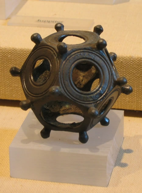
Figure 1. A roman dodecahedron (free source of the image: Wikipedia, creator DieBuche).
according to the data of one of them given in Ref. [11]. This reference is reporting the sizes of the holes (see Figure 2). The dodecahedron, found at Jublains, the ancient Nouiodunum, is dating from the 2nd or 3rd century AD. In [8], I proposed this Roman object for measuring distance, using a method based on similar triangles (this method will be discussed in the last section of this paper, where a rangefinder for students is proposed).
The roman dodecahedron possesses six angles of view, and, knowing the size of an object allows determining its distance. The angle of view is the cone that describes the angular extent of a given scene.
Naming 1,2,3,4,5, and 6, the holes of face A, and 1',2',3',4',5' and 6' the holes, of face B (see Figure 2), we have the following opposite pairs: (1',1), (2',6), (3',5), (5',3), (4',4) and (6',2). Let us consider for instance, the pair (2',6) and look through the dodecahedron, holding it with 2' and 6 parallel, with 2' near an eye and 6 as opposite.
If the dodecahedron is close the eye, we see the two holes (see Figure 3); if it is too far, we see just the nearest hole 2'. There is a distance from eye, where we can see the circumferences of the two holes as perfectly superimposed, that is, we have a coincidence of the images of the two holes. This gives the precise angle of view, which we can use for measurements.
Points O,O" and G are given in Figure 3 [8]. OO" is

Figure 2. Faces of the roman dodecahedron of Ref. [11].

Figure 3. Let us consider the pair (2',6) and look at a Roman vexillum through the dodecahedron, holding it with 2' and 6 parallel, with 2' near an eye and 6 opposite. If the dodecahedron is close the eye, we see the two holes. If it is too far, we can see just hole 2'. There is a distance from eye, where we can see the circumferences of the two holes (black and grey in the image) as perfectly superimposed (coincidence). This specific cone of view we can use for measurements, as shown in the upper sketch.
the eye-line. After the sizes of holes, we have for the pairs of the dodecahedron the ratios given in Table 1 (holes 1 and 1' are not included because elliptic).
Let us use the following example to show how to measure distance. A Roman soldier is looking through the dodecahedron at a target, for instance a vexillum, that he knows it has a height of two meters. If the soldier sees the vexillum fitted in the field of view of the pair (2',6), that is, with its height coincident with the diameter of the superimposed circumferences 2' and 6, he can determine its distance. Looking at the Table 1, for the vexillum 2 meters long, GO" = 1 m, then OO" » 15 m. This is the result for pair (2',6). Using the other pairs, we have distances of 25 m, 100 m and 200 m, respectively. Then the soldier can use the device for four different ranges.
We can easily test the copy of the dodecahedron found in Jublain in a room, using a given object. In the case of the small vase shown in the Figure 4, which is 0.2 m high, we used the pair (3',5). The dodecahedron was at 2.5 meters. We can observe the two circumferences as superimposed and the object perfectly fitted in the hole.
Of course, it is not necessary that the target is perfectly fitting the hole. It is necessary that the observer, looking through the dodecahedron, is able to estimate the size of the scene containing the target. In this way, he will be able to evaluate an approximate distance of it.
The dodecahedrons having a structure with holes of different sizes are therefore military instruments to evaluate distances for ballistics.
3. The Fore-Staff
The previously discussed dodecahedron, being of bronze

Table 1. Pairs of the dodecahedron.

Figure 4. A “room version” of the sketch in Figure 3, obtained with the pair (3',5) of a dodecahedron made of cardboard. The vase is 0.2 m high and, when we see the coincidence as the image on the right, according to Table 1 the dodecahedron is at a distance of 2.5 m from it.
was quite strong and portable. Considering it as a rangefinder of the Roman Army, its use was lost after the collapse of the Empire. It seems that the Middle Age developed a different rangefinder, or used an already known device. It was the fore-staff. The noun “fore-staff” is referring to several things and therefore it is a little bit confusing. The best is to describe it according to its use. It is also known as Jacob’s staff or cross-staff when it is used for astronomy and navigation, as a device to measure angles, later replaced by sextants. In surveying, it is a vertical rod penetrating the ground, supporting a compass for measuring angles.
As told in Ref. [12], the fore-staff is also known as “ballista”. In fact, the ballista is an ancient military engine, which was used for throwing stones, darts and javelins. Therefore the rangefinder used to determine the distance of the target was named after its ballistic machine.
As we can see in the Figure 5, it is quite simple and its use based on similar triangles again. In the original form of the fore-staff, it is a pole (the main staff) marked with graduations for length. A crosspiece, called transom or transversal, slides on the main staff. It was common to provide several transoms, each with a different range of angles it would measure.
This rangefinder is quite large; moreover, it has the drawback that one needs to change the transom for targets at different distances. The dodecahedron is small, and to change the range, it is enough to rotate it. It has the same features as the fore staff, but is more convenient for military actions.

Figure 5. Fore-staff and how to use it on an eye-line.
4. The Coincidence Rangefinder
The modern rangefinders are used for determining the focus in photography, or again, as we have discussed before, for accurately aiming a weapon. Some instruments are based on active methods, using emission of energy by means of sonar, laser, or radar. The laser rangefinder can operate on the time of flight principle. They launch a laser pulse towards the object and measure the time this pulse needs to come back to the instrument. Moreover, according to the Doppler Effect, it is possible to measure how fast the target is moving.
However, the use of optical instruments based on triangulation methods persists (stadiametric rangefinders, parallax, and coincidence rangefinders) [13]. These optical methodologies have been in regular use since the 18th century. Ref. [14] reports that the coincidence rangefinder uses a single eyepiece. It is more or less a cylinder. Light from the target enters through two windows spaced apart on the cylinder. The distance between these windows is the base-length B of the rangefinder. The incident beams are reflected to the centre of the optical cylinder by prisms to form two images of the target, which are viewed by the observer through the eyepiece. Since the beams enter the instrument at slightly different angles, an observer sees a blurry image. Adjusting a compensator, the observer can tilt one of the beams to match the two images. In such a manner, the images are “in coincidence”. The rotation of the compensator gives the distance of the target by triangulation. Ref. [15] is proposing a simple coincidence instrument (see Figure 6).
It is told in [15] that the rangefinder operates as an angle-measuring device, using the triangle comprising the rangefinder base-length B and the line from each window to the target point. The basic optical arrangement is shown in Figure 6, where the mirror in front of the eyepiece is semitransparent. When we have the coincidence, the target T is seen in the same apparent position. We have that the rangefinder equation is satisfied. The distance D from the target is: D = B cot A.
The fact that we need to have a coincidence of images, is, more or less the same condition we need for the use of

Figure 6. Simple coincidence rangefinder. The two lines converging at the target are forming an angle A.
a Roman Dodecahedron, where we have to find the coincidence of the circumferences of opposite holes. Therefore, we could tell that it was the Roman coincidence rangefinder.
5. A Rangefinder for Students
One of the best approaches for teaching the measure of a physical quantity is that the students develop their own instruments. The measure of distance using a rangefinder is quite suitable for this approach. After discussing with students the rangefinders as we did in the previous sections, we can invite them to prepare their own Roman rangefinder. For the sake of simplicity, we can ask them to create a cubic device, having just one angle of view. For instance, they can use a cardboard small box and two plumbing gaskets, having holes of different sizes (see Figure 7).
To shows how we can determine the distances, let us consider Figure 8. BC is the diameter of the smaller hole, EF the diameters of the larger one. A is the observer’s eye. GH is the size of the scene we see through the holes when we see their images as coincident. This happens at the proper distance AO of the smaller hole from the eye. OO' is the distance of the two holes. GH is the object we are observing. From the figure, we can obtain that:
 (1)
(1)
Let us suppose , then:
 (2)
(2)
and therefore:
 (3)
(3)
We have;
 (4)
(4)
In the case of our vase in the room experiment, we see that it is occupying one half of the diameter (see Figure 9 on the right). Therefore GH = 0.4 m, we have: OO" = 4 ´ 102 mm ´ 70 mm/(12 mm) » 2.33 m.

Figure 7. On the opposite sides of a box, we can create two holes of different size using two plumbing gaskets.

Figure 8. Geometry of Figure 7. Vertex A corresponds to the observer’s eye. The aperture of the cone GAH is the angle of view of this simple rangefinder.

Figure 9. The same object of Figure 4 in a room experiment using the rangefinder of Figure 7. On the right, we see the coincidence.
In a room experiment, we can directly check the distance. However, we can use the rangefinder to observe for instance, the windows of the surrounding buildings or other objects. To check the distances we can use the satellite maps that we have freely on the Web, for instance the Google Maps, and the scales reported on them.
6. Conclusion
This paper is proposing an instrument that each student can easily prepare for studying a surveying method to determine the distance. This instrument is modelled on an ancient Roman artefact that the Roman Army probably used as a rangefinder for ballistics. The method is based on coincidence of images and triangulation. It is important to remark that each student can have a personal instrument at practically no cost.
REFERENCES
- University of Cincinnati, Army Reserve Officers’ Training Corps (ROTC), “Land Navigation,” 2012. http://www.uc.edu/armyrotc/ms2text/MSL_201_L03b_Land_Navigation.pdf
- Random House, Inc., “Range,” 2012. http://dictionary.reference.com/browse/range
- D. Harper, “Online Etymology Dictionary,” 2012. http://www.etymonline.com
- Merriam-Webster’s, Online Dictionary, An Encyclopaedia Britannica Company, “Range Finder,” 2012. http://www.merriam-webster.com/dictionary/range%20finder
- J. Caesar, “Caesar’s Commentaries,” No. 702 Everyman’s Library, Ernest Rhys Editor, New York, 1929.
- C. Rossi, F. Russo and F. Russo, “Ancient Engineers' Inventions: Precursors of the Present,” Springer Verlag, New York, 2009.
- W. A. Schmidt, “The Surveyor’s Cross,” Professional Surveyor Magazine, 2007. http://www.profsurv.com/magazine/article.aspx?i=1803
- A. C. Sparavigna, “A Roman Dodecahedron for Measuring Distance,” 2012. http://arxiv.org/abs/1204.6497
- Wikipedia, “Roman Dodecahedron,” 2012. http://en.wikipedia.org/wiki/Roman_dodecahedron
- A. C. Sparavigna. “An Etruscan Dodecahedron,” 2012. http://arxiv.org/abs/1205.0706
- G. Guillier, R. Delage and P. A. Besombes, “Une Fouille en Bordure des Thermes de Jublains (Mayenne): Enfin un Dodécaèdre en Contexte Archéologique!,” Revue Arché- ologique de l’Ouest, Vol. 25, 2008, pp. 269-289.
- Peter Barlow, “A New Mathematical and Philosophical Dictionary,” Whittingham and Rowland, London, 1814.
- Wikipedia, “Rangefinder,” 2012. http://en.wikipedia.org/wiki/Rangefinder
- Wikipedia, “Coincidence Rangefinder,” 2012. http://en.wikipedia.org/wiki/Coincidence_rangefinder
- “Rangefinder,” Encyclopedia of Science and Technology, 6th Edition, McGraw-Hill, New York, 1996.