Intelligent Control and Automation, 2011, 2, 371-382
doi:10.4236/ica.2011.24042 Published Online November 2011 (http://www.SciRP.org/journal/ica)
Copyright © 2011 SciRes. ICA
id-iq Control Strategy for Mitigation of Current Harmonics
with Fuzzy Logic Controller Using Matlab/Simulation and
RTDS Hardware
Suresh Mikkili, Anup Kumar Panda
Department of Electrical Engineering, National Institute of Technology, Rourkela, India
E-mail: {msuresh.ee, akpanda.ee}@gmail.com
Received June 28, 2011; revised July 20, 2011; accepted August 27, 2011
Abstract
The main objective of this paper is to develop Fuzzy controller to analyse the performance of instantaneous
real active and reactive current (id-iq) control strategy for extracting reference currents of shunt active filters
under balanced, un-balanced and balanced non-sinusoidal conditions. When the supply voltages are balanced
and sinusoidal, the all control strategies are converge to the same compensation characteristics; However, the
supply voltages are distorted and/or un-balanced sinusoidal, these control strategies result in different de-
grees of compensation in harmonics. The p-q control strategy unable to yield an adequate solution when
source voltages are not ideal. Extensive simulations are carried out with Fuzzy controller for id-iq control
strategy under different main voltages. The 3-ph 4-wire shunt active filter (SHAF) system is also imple-
mented on a Real Time Digital Simulator (RTDS Hardware) to further verify its effectiveness. The detailed
simulation and RTDS Hardware results are included.
Keywords: Harmonic Compensation, SHAF, id-iq Control Strategy, Fuzzy Controller and RTDS Hardware
1. Introduction
As nonlinear currents flow through a facility’s electrical
system and the distribution-transmission lines, additional
voltage distortions are produced due to the impedance
associated with the electrical network. Thus, as electrical
power is generated, distributed, and utilized, voltage and
current waveform distortions are produced. It is noted
that non-sinusoidal current [1] results in many problems
for the utility power supply company, such as: low
power factor, low energy efficiency, electromagnetic in-
terference (EMI), distortion of line voltage etc.
The PI controller [2] requires precise linear mathe-
matical models, which are difficult to obtain and may not
give satisfactory performance under parameter variations,
load disturbances, etc. Recently, fuzzy logic controllers
[3] have received a great deal of interests in APF. The
advantages of fuzzy controllers over conventional con-
trollers are that they do not need an accurate mathemati-
cal model, can work with imprecise inputs, can handle
non-linearity, and are more robust than conventional
controllers. The Mamdani type of fuzzy controller used
for the control of APF [4] gives better results compared
with the PI controller, but it has the drawback of a larger
number of fuzzy sets and 49 rules.
In our previous publication [5], we developed Fuzzy
controller to analyse the performance of instantaneous
real active and reactive power (p-q) control strategy [6
for extracting reference currents of shunt active filters
under balanced, un-balanced and balanced non-sinusoi-
dal conditions. Fuzzy controller based p-q theory shows
dynamic performance than p-q method with PI controller.
p-q theory needs additional PLL circuit for synchroniza-
tion so p-q method is frequency variant.
In id-iq method [7] angle “θ” is calculated directly
from main voltages and thus enables the method to be
frequency independent. Thus large numbers of synchro-
nization problems with un-balanced and non-sinusoidal
voltages are also avoided.
Present paper mainly focused on Fuzzy controller to
analyse the performance of instantaneous real active and
reactive current (id-iq) control strategy for extracting ref-
erence currents of shunt active filters under different
voltage conditions. PWM pattern generation based on
carrier less hysteresis based current control is used for
quick response. Additionally, on contrast of different
S. MIKKILI ET AL.
372
control strategies; id-iq method is used for obtaining ref-
erence currents in the system, because in this strategy,
angle “θ” is calculated directly from main voltages and
enables operation to be frequency independent their by
technique avoids large numbers of synchronization
problems. It is also observed that DC voltage regulation
system valid to be a stable and steady-state error free
system was obtained. Thus with fuzzy logic and (id-iq)
approaches a novel shunt active filter can be developed.
Even though two control strategies [8] with two con-
trollers are capable to compensate current harmonics in
the 3 phase 4-wire system, but it is observed that id-iq
method with Fuzzy Logic controller gives an outstanding
performance over id-iq method with PI controller and also
than that of p-q with PI and Fuzzy controllers.
2. Shunt Active Filter Configuration
The active filter currents [9] are achieved from the in-
stantaneous active and reactive powers p and q of the
non-linear load. Figure 1 shows a three-leg structure
with the neutral conductor being connected to midpoint
of dc-link capacitor.
The three-leg six-switch split-capacitor [10] configu-
ration of shunt APF suffers from several shortcomings
viz.
1) Control circuit is somewhat complex;
2) Voltages of the two capacitors of split-capacitor
need to be properly balanced;
3) Large dc-link capacitors are required.
Compensation Principle
The active power filter is controlled to draw/supply the a
compensating current if from/to the load to cancel out the
current harmonics on AC side and reactive power flow
from/to the source there by making the source current in
Figure 1. Three-leg split capacitor shunt APF with non-
linear load.
phase with source voltage. Figure 2 shows the basic
compensation principle of the active power filter.
3. Instantaneous Active and Reactive Power
(id-iq) Method
In Figure 3, the entire reference current generation
scheme has been illustrated. The load currents iLa, iLb and
iLc are tracked upon which Park’s transformation is per-
formed to obtain corresponding d-q axes currents iLd and
iLq as given in (1), where
is rotational speed of syn-
chronously rotating d-q frame. According to id-iq control
strategy, only the average value of d-axis component of
load current should be drawn from supply. Here iLd1h and
iLq1h indicate the fundamental frequency component of
iLd and iLq. The oscillating components iLd and iLq i.e.,
iLdnh and iLqnh are filtered out using low-pass filter.
LdLd1h Ldnh
LqLq1h Lqnh
La
Ld
Lb
Lq
Lc
iii
iii
i
11/2 1/2
isin cosi
icossin 03/2 3/2
i
wt wt
wt wt
 
 
 







 
(1)
The currents iLdnh and iLqnh along with id1h are utilized
to generate reference filter currents icd* and icq* in d-q
coordinates, followed by inverse Park transformation
giving away the compensation currents ica*, icb*, icc* and
icn* in the four wires as described in (2) and (3).
Figure 2. Compensation characteristics of a shunt active
ower filter.
p
Copyright © 2011 SciRes. ICA
S. MIKKILI ET AL.
Copyright © 2011 SciRes. ICA
373
Figure 3. Active powers filter control circuit.


*
ca cd
*
cb cq
*
cc c0
isin cos1
isin2π3cos 2π31i
isin2π3cos 2π31i
wt wt
wt wt
wt wt
 
 
 
 
 

 
*
*
*
i
*
(2)
cn
***
ca cb cc
iiii (3)
Reference currents are extracted with id-iq method us-
ing Fuzzy controller which is shown in Figure 4. The
reference signals thus obtained are compared with the
actual compensating filter currents in a hysteresis com-
parator, where the actual current is forced to follow the
reference and provides instantaneous compensation by
the APF [11] on account of its easy implementation and
quick prevail over fast current transitions. This conse-
quently provides switching signals to trigger the IGBTs
inside the inverter. Ultimately, the filter provides neces-
sary compensation for harmonics in the source current
and reactive power unbalance in the system. Figure 6
shows voltage and current vectors in stationary and ro-
tating reference frames. The transformation angle “θ” is
sensible to all voltage harmonics and unbalanced volt-
ages; as a result dθ/dt may not be constant.
One of the advantages of this method is that angle θ is
calculated directly from main voltages and thus makes
this method frequency independent by avoiding the PLL
in the control circuit. Consequently synchronizing prob-
lems with unbalanced and distorted conditions of main
voltages are also evaded. Thus id-iq achieves large fre-
quency operating limit essentially by the cut-off fre-
quency of voltage source inverter (VSI) [12].
Figures 4 and 5 show the control diagram for shunt
active filter and harmonic injection circuit. On owing
load currents id and iq are obtained from park transforma-
tion then they are allowed to pass through the high pass
filter to eliminate dc components in the nonlinear load
currents. Filters used in the circuit are Butterworth type
and to reduce the influence of high pass filter an alterna-
tive high pass filter (AHPF) can be used in the circuit. It
S. MIKKILI ET AL.
374
a-b-
c
to d-
q
-0
Transformation
F
UZZY
L
PF
L
PF
d-q-0 to a-b-
c
Transformation
V
dc
V
dc
*
+
_
V
dc
i
L
a
i
L
b
i
L
c
i
d
i
L
q
i
L
d1h
i
L
q1h
i
L
dnh
i
L
qnh
i
cd
*
i
cq
*
i
d1h
_
_
+
+
+
+
-1
i
0
i
cabc
*
i
cn
*
Figure 4. Reference current extraction with id-iq method with Fuzzy controller.
Figure 5. Instantaneous voltage and current vectors.
can be obtained through the low pass filter (LPF) of
same order and cut-off frequency simply difference be-
tween the input signal and the filtered one, which is
clearly shown in Figure 4. Butterworth filters used in
harmonic injecting circuit have cut-off frequency equal
to one half of the main frequency (fc = f/2), with this a
small phase shift in harmonics and sufficiently high tran-
sient response can be obtained.
4. Construction of Fuzzy Controller
The concept of Fuzzy Logic (FL) was proposed by Pro-
fessor Lotfi Zadeh in 1965, at first as a way of process-
ing data by allowing partial set membership rather than
crisp membership. Soon after, it was proven to be an
excellent choice for many control system applications
since it mimics human control logic.
The bock diagram of Fuzzy logic controller is shown
in Figure 6. It consists of blocks:
Fuzzification Interface;
Knowledge base;
Decision making logic;
Defuzzification.
Figure 7 shows the internal structure of the control
circuit. The control scheme consists of Fuzzy controller
[13], limiter, and three phase sine wave generator for
reference current generation and generation of switching
signals. The peak value of reference currents is estimated
by regulating the DC link voltage. The actual capacitor
voltage is compared with a set reference value. The error
signal is then processed through a Fuzzy controller,
which contributes to zero steady error in tracking the
reference current signal.
A fuzzy controller converts a linguistic control strat-
egy into an automatic control strategy, and fuzzy rules
are constructed by expert experience or knowledge data-
base [14]. Firstly, input voltage Vdc and the input refer-
ence voltage Vdc-ref have been placed of the angular ve-
locity to be the input variables of the fuzzy logic con-
troller. Then the output variable of the fuzzy logic con-
troller is presented by the control Current Imax. To con-
vert these numerical variables into linguistic variables,
the following seven fuzzy levels or sets are chosen as:
NB (negative big), NM (negative medium), NS (negative
small), ZE (zero), PS (positive small), PM (positive me-
dium), and PB (positive big) as shown in Figure 8.
Rule Base: The elements of this rule base table are
determined based on the theory that in the transient state,
large errors need coarse control, which requires coarse
input/output variables; in the steady state, small errors
need fine control, which requires fine input/output vari-
ables. Based on this the elements of the rule table are
obtained as shown in Table 1, with “Vdc” and “Vdc-ref” as
inputs.
The fuzzy controller is characterized as follows:
1) Seven fuzzy sets for each input and output.
2) Fuzzification using continuous universe of discour-
e. s
Copyright © 2011 SciRes. ICA
S. MIKKILI ET AL.
Copyright © 2011 SciRes. ICA
375
Figure 6. Block diagram of fuzzy lozic controller.
Figure 7. Conventional fuzzy controller.
3) Implication using Mamdani’s “min” operator.
4) Defuzzification using the “centroid” method.
5. RTDS Hardware
This simulator was developed with the aim of meeting
the transient simulation needs of electromechanical
drives and electric systems while solving the limitations
of traditional real-time simulators which is shown in
Figure 9. It is based on a central principle: the use of
widely available, user-friendly, highly competitive com-
mercial products (PC platform, Simulink™). The real-
time simulator [15] consists of two main tools: a
real-time distributed simulation package (RT-LAB) for
the execution of Simulink block diagrams on a
PC-cluster, and algorithmic toolboxes designed for the
fixed-time-step simulation of stiff electric circuits and
their controllers. Real-time simulation and Hardware-In-
the-Loop (HIL) applications are increasingly recognized
Table 1. Rule base.
(de/dt)/eNBNMNS Z PS PMPB
NB NBNBNB NB NM NSZ
NM NBNBNB NM NS Z PS
NS NBNBNM NS Z PS PM
Z NBNMNS Z PS PMPB
PS NMNS Z PS PM PBPB
PM NS Z PS PM PB PBPB
PB Z PS PM PB PB PBPB
S. MIKKILI ET AL.
376
(a)
(b)
(c)
Figure 8. (a) Input Vdc normalized membership function; (b) input Vdc-ref normalized MF; (c) output Imax normalized MF.
Figure 9. RTDS hardware.
as essential tools for engineering design and especially in
power electronics and electrical systems.
Simulator Architecture
1) Block Diag r am and Schematic Interface
The present real-time electric simulator is based on RT
LAB real-time, distributed simulation platform; it is op-
timized to run Simulink in real-time, with efficient
fixed-step solvers, on PC Cluster. Based on COTS
non-proprietary PC components, RT LAB is a modular
real-time simulation platform, for the automatic imple-
mentation of system-level, block diagram models, on
standard PC’s. It uses the popular MATLAB/Simulink as
a front-end for editing and viewing graphic models in
block-diagram format. The block diagram models be-
Copyright © 2011 SciRes. ICA
S. MIKKILI ET AL.377
come the source from which code can be automatically
generated, manipulated and downloaded onto target
processors (Pentium and Pentium-compatible) for real-
time or distributed simulation.
2) Inputs and Outputs (I/O)
A requirement for real-time HIL applications is inter-
facing with real world hardware devices, controller or
physical plant alike. In the RT-LAB real-time simulator,
I/O interfaces are configured through custom blocks,
supplied as a Simulink toolbox. The engineer merely
needs to drag and drop the blocks to the graphic model
and connect the inputs and outputs to these blocks,
without worrying about low-level driver programming.
RT-LAB manages the automatic generation of I/O driv-
ers and models code so to direct the model’s data flow
onto the physical I/O cards.
3) Simulator Configuration
In a typical configuration (Figure 10), the RT-LAB
simulator consists of
One or more target PC’s (computation nodes); one of
the PCs (Master) manages the communication be-
tween the hosts and the targets and the communica-
tion between all other target PC’s. The targets use the
REDHAT real-time operating system.
One or more host PC’s allowing multiple users to
access the targets; one of the hosts has the full control
of the simulator, while other hosts, in read-only mode,
can receive and display signals from the real-time
simulator.
I/O’s of various types (analog in and out, digital in
and out, PWM in and out, timers, encoders, etc).
I/O’s can be managed by dedicated processors dis-
tributed over several nodes.
6. Simulation and RTDS Results
Figures 11, 12 and 13 illustrates the performance of
shunt active power filter under different main voltages,
as load is highly inductive, current draw by load is inte-
grated with rich harmonics.
Figure 11 illustrates the performance of Shunt active
power filter under balanced sinusoidal voltage condition,
THD for id-iq method with Fuzzy Controller using matlab
simulation is 0.97% and using RT DS Hard ware is
1.26%.
Figure 12 illustrates the performance of Shunt active
power filter under un-balanced sinusoidal voltage condi-
tion, THD for id-iq method with Fuzzy Controller using
matlab simulation is 1.64% and using RT DS Hard ware
is 1.94%.
Figure 13 illustrates the performance of Shunt active
power filter under balanced non-sinusoidal voltage con-
dition, THD for id-iq method with Fuzzy Controller using
matlab simulation is 3.01% and using RT DS Hard ware
is 3.54%.
Figure 14 gives the Total Harmonic Distortion (THD)
comparison of id-iq control strategy with Fuzzy Control-
ler Using Matlab/Simulink and RTDS Hardware.
Figure 10. RT-LAB simulator architecture.
Copyright © 2011 SciRes. ICA
S. MIKKILI ET AL.
378
3ph 4w Bal Sin I
d
-I
q
with Fuzzy Controller
( MATLAB Simulation)
3ph 4w Bal Sin I
d
-I
q
with Fuzzy Controller
( RT DS Hardware)
0.352 0.354 0.356 0.3580.360.362 0.364 0.366 0.3680.37 0.372
-400
-300
-200
-100
0
100
200
300
400
Time (Sec)
Source Voltage (Volts)
0.352 0.354 0.356 0.3580.360.362 0.364 0.366 0.368 0.37 0.372
-150
-100
-50
0
50
100
150
Time (Sec)
Source Current (Amps)
0.352 0.354 0.356 0.3580.360.362 0.364 0.366 0.3680.37 0.372
-40
-30
-20
-10
0
10
20
30
40
Time (Sec)
Load Current (Amps)
0.352 0.354 0.356 0.3580.360.362 0.364 0.366 0.3680.37 0.372
-150
-100
-50
0
50
100
150
Time (Sec)
Filter Current (Amps)
0.352 0.354 0.356 0.3580.360.362 0.364 0.366 0.368 0.37 0.372
0
200
400
600
800
1000
Time (sec)
DC Link Voltage (Volts)
010 20 3040 50
0
0.2
0.4
0.6
0.8
1
Harmonic order
THD= 0.97%
Mag (% of Fundamental)
(a) (b)
Figure 11. id-iq with fuzzy controller unde r balanced sinusoidal (a) matlab simulation; (b) RT DS hardwa re .
Copyright © 2011 SciRes. ICA
S. MIKKILI ET AL.379
3ph 4w Un-bal Sin Id-Iqwith Fuzzy Controller
( MATLAB Simulation)
3ph 4w Un-bal Sin I
d
-I
q
with Fuzzy Controller
( RT DS Hardware)
0.352 0.354 0.356 0.3580.36 0.362 0.3640.366 0.3680.370.372
-400
-300
-200
-100
0
100
200
300
400
Time (Sec)
Source Voltage (Volts)
0.352 0.354 0.356 0.3580.36 0.362 0.3640.366 0.3680.370.372
-150
-100
-50
0
50
100
150
Time (Sec)
Source Current (Amps)
0.352 0.354 0.356 0.3580.36 0.362 0.3640.366 0.3680.370.372
-40
-30
-20
-10
0
10
20
30
40
Time (Sec)
Load Current (Amps)
0.352 0.354 0.356 0.3580.36 0.362 0.364 0.366 0.3680.370.372
-150
-100
-50
0
50
100
150
Time (Sec)
Filter Current (Amps)
0.352 0.3540.356 0.3580.360.362 0.364 0.366 0.3680.370.372
0
200
400
600
800
1000
Time (Sec)
DC Link Voltage (Volts)
010 20 30 4050
0
0.2
0.4
0.6
0.8
1
Harmonic order
THD= 1. 64%
Mag (% of Fundamental)
(a) (b)
Figure 12. id-iq with fuzzy controlle r under un-bal sin, (a) matlab simulation; (b) RT DS hardware.
Copyright © 2011 SciRes. ICA
S. MIKKILI ET AL.
380
3ph 4w Non-Sin I
d
-I
q
w
ith Fuzzy Controller
( MATLAB Simulation)
3ph 4w Non-Sin Id-Iq
w
ith Fuzzy Controller
( RT DS Hardware)
0.3520.354 0.3560.3580.360.362 0.364 0.3660.3680.370.372
-400
-300
-200
-100
0
100
200
300
400
Time (Sec)
Source Voltage (Volts)
0.3520.354 0.3560.3580.36 0.362 0.364 0.3660.3680.370.372
-150
-100
-50
0
50
100
150
Time (Sec)
Source Current (Amps)
0.3520.354 0.3560.3580.360.362 0.364 0.3660.3680.370.372
-40
-30
-20
-10
0
10
20
30
40
Time (Sec)
Load Current (Amps)
0.3520.354 0.3560.3580.360.3620.364 0.366 0.3680.370.372
-150
-100
-50
0
50
100
150
Time (Sec)
Filter Current (Amps)
0.352 0.354 0.3560.3580.360.3620.364 0.3660.3680.370.372
0
200
400
600
800
1000
Time
(
Sec
)
DC Link Voltage (Volts)
010 20 3040 50
0
0.2
0.4
0.6
0.8
1
Harmonic order
THD= 3.01%
Mag (% of Fundamental)
(a) (b)
Figure 13. id-iq with fuzzy controller unde r non-sin (a) Matlab simulation; (b) RT DS hardware.
Copyright © 2011 SciRes. ICA
S. MIKKILI ET AL.
Copyright © 2011 SciRes. ICA
381
Figure 14. THD for id-iq method with fuzzy controller using Matlab and RTDS hardware.
7. Conclusions [5] S. Mikkili, A. K. Panda and S. Yellasiri, “RTDS Hard-
ware Implementation and Simulation of 3-ph 4-Wire
SHAF for Mitigation of Current Harmonics Using p-q
Control Strategy with Fuzzy Controller,” Journal of
Power Electronics & Power Systems, Vol. 1, No. 1, 2011,
pp. 13-23.
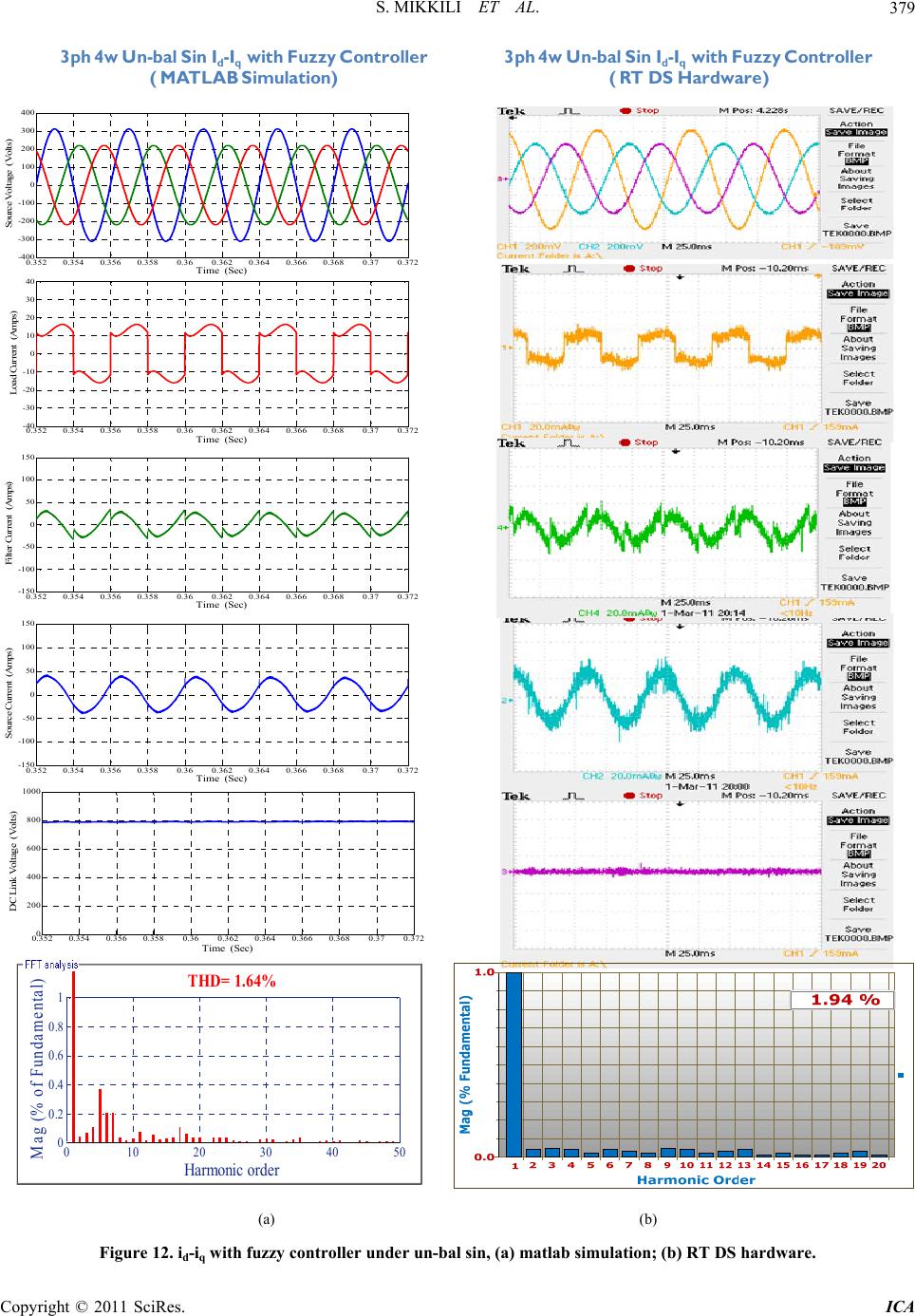
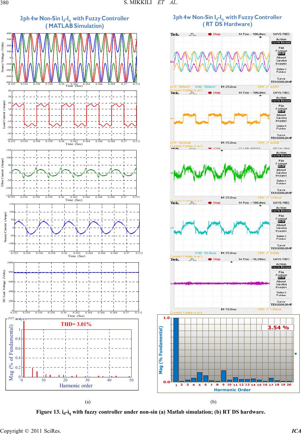
In the present paper instantaneous active and Reactive
current control strategy with Fuzzy controller is devel-
oped to mitigate the current harmonics in three phase
four wire system using Matlab/simulink environment and
it verified with Real Time Digital Simulator. This control
strategy is capable to suppress the harmonics in the sys-
tem during balanced sinusoidal, un-balanced sinusoidal
and balanced non-sinusoidal conditions. The p-q control
strategy is unable to yield an adequate solution when
source voltages are not ideal. p-q theory needs additional
PLL circuit for synchronization so p-q method is fre-
quency variant, where as in id-iq method angle “θ” is
calculated directly from main voltages and thus enables
the method to be frequency independent. Thus large
numbers of synchronization problems with un-balanced
and non-sinusoidal voltages are also avoided. Addition to
that DC voltage regulation system valid to be a stable
and steady-state error free system was obtained.
[6] F. Z. Peng, G. W. Ott Jr. and D. J. Adams, “Harmonic and
reactive Power Compensation Based on the Generalized
Instantaneous Reactive Power Theory for Three-Phase
Four-Wire Systems,” IEEE Transactions on Power Elec-
tronics, Vol. 13, No. 5, 1998, pp. 1174-1181.
doi:10.1109/63.728344
[7] V. Soares, P. Verdelho and G. Marques, “Active Power
Filter Control Circuit Based on the Instantaneous Active
and Reactive Current id-iq Method,” IEEE Power Elec-
tronics Specialists Conference, St. Louis, 22-27 June
1997, pp. 1096-1101.
[8] M. I. M. Montero, E. R. Cadaval and F. B. Gonzalez,
“Comparison of Control Strategies for Shunt Active
Power Filters in Three-Phase Four Wire Systems,” IEEE
Transactions on Power Electronics, Vol. 22, No. 1, 2007,
pp. 229-236. doi:10.1109/TPEL.2006.886616
[9] M. Aredes, J. Hafner and K. Heumann, “Three-Phase
4-Wire Shunt Active Filter Control Strategies,” IEEE
Transactions on Power Electronics, Vol. 12, No. 2, 1997,
pp. 311-318. doi:10.1109/63.558748
8. References
[1] H. Akagi, Y. Kanazawa and A. Nabae, “instantaneous
Reactive Power Compensators Comprising Switching
Devices without Energy Storage Components,” IEEE
Transactions on Industry Applications, Vol. IA-20, No. 3,
1984, pp. 625-630.
[10] P. Rodriguez, J. I. Candela, A. Luna and L. Asiminoaei,
“Current Harmonics Cancellation in Three-Phase Four-
Wire Systems by Using a Four-Branch Star Filtering To-
pology,” IEEE Transactions on Power Electronics, Vol.
24, No. 8, 200, pp. 1939-19509.
doi:10.1109/TPEL.2009.2017810
[2] L. Gyugyi and E. C. Strycula, “Active AC Power Filters,”
IEEE IIAS Annual Meeting, Cincinnati, 1976, pp. 529-535.
[3] M. Suresh, A. K. Panda and Y. Suresh, “Fuzzy Controller
Based 3Phase 4Wire Shunt Active Filter for Mitigation of
current Harmonics with Combined p-q and id-iq Control
Strategies,” Journal of Energy and Power Engineering,
Vol. 3, No. 1, 2011, pp. 43-52.
doi:10.4236/epe.2011.31007
[11] P. Salmeron and R. S. Herrera, “Distorted and Unbal-
anced Systems Compensation within Instantaneous Reac-
tive Power Framework,” IEEE Transactions on Power
Delivery, Vol. 21, No. 3, 2006, pp. 1655-1662.
doi:10.1109/TPWRD.2006.874115
[12] S. Mikkili and A. K. Panda, “APF for Mitigation of Cur-
rent Harmonics with p-q and id-iq Control Strategies Us-
ing PI Controller,” Journal of Trends in Electrical Engi-
neering, Vol. 1, No. 1, 2011, pp. 1-11.
[4] H. Akagi, “New Trends in Active Filters for Power Con-
ditioning,” IEEE Transactions on Industry Applications,
Vol. 32, No. 6, 1996, pp. 1312-1322.
S. MIKKILI ET AL.
382
[13] S. K. Jain, et al., “Fuzzy Logic Controlled Shunt Active
Power Filter for Power Quality Improvement,” IEEE
Proceedings of Electric Power Applications, Vol. 149,
No. 5, 2002, pp. 317-328.
[14] S. Mikkili and A. K. Panda, “Simulation and RTDS
Hardware Implementation of SHAF for Mitigation of
Current Harmonics with p-q and id-iq Control Strategies
Using PI Controller,” Engineering, Technology & Ap-
plied Science Research, Vol. 1, No. 3, 2011, pp. 54-62.
[15] P. Forsyth, et al., “Real Time Digital Simulation for Con-
trol and Protection System Testing,” IEEE 35th Annual
Power Electronics Specialists Conference, Aachen, 20-25
June 2004, pp. 329-335.
Copyright © 2011 SciRes. ICA