 Advances in Chemical Engi neering and Science , 2011, 1, 280-288 doi:10.4236/aces.2011.14039 Published Online October 2011 (http://www.SciRP.org/journal/aces) Copyright © 2011 SciRes. ACES Industrial Progress: New Energy-Efficient Absorbents for the CO2 Separation from Natural Gas, Syngas and Flue Gas Jörn Rolker, Matthias Seiler* Evonik Industries AG, New Business Develop ment, BU Advanced Intermediates, Hanau, Germany E-mail: *matthias.seiler@evonik.com Recieved July 19, 2011; revised August 4, 2011; accepted Augu st 20, 2011 Abstract The CO2 separation from natural gas, syngas or flue gas represents an important industrial field of applica- tions. An economic and energy-efficient CO2 separation from these gas streams is a prerequisite for sustain- able industry contributions to the megatrends resource efficiency and globalization of technologies. One way of reducing operational expenditure for these separation processes is the development of better performing CO2 absorbents. Although a number of absorbents for the separation of CO2 from process gas streams exist, the need for the development of CO2 absorbents with an improved absorption performance, less corrosion and foaming, no nitrosamine formation, lower energy requirement and therefore less operational expenditure remains. Recent industrial activities have led to the development of novel high-performance CO2 scrubbing agents that can be employed in numerous industrial processes such as natural gas treatment, purification of syngas and the scrubbing of flue gas. The objective of this paper is to introduce these new high-performance scrubbing agents and to compare their performance with other state-of-the-art absorbents. It turned out, that the evaluated absorbents offer high cyclic capacities in the range of 2.4 to 2.6 mol CO2/kg absorbent and low absorption enthalpies (–30 kJ/mol) allowing for distinctive savings in the regeneration energy of the absor- bent. Calculations with the modified Kremser model resulted in a reduction of the specific reboiler heat duty of 55%. Furthermore, the absorbents are less corrosive than standard amines as indicated by the measured corrosion rates of 0.21 mm/y versus 1.18 mm/y for a piperazine/methyldiethanolamine mixture. Based on new experimental results it is shown how substantial savings in operational and capital expenditure can be realized due to favorable absorbent properties. The novel high-performance CO2 system solutions meet re- cent industrial absorbent requirements and allow for more efficient or new CO2 separation processes. Keywords: Absorbent, CO2, Energy Efficiency, Sustainability, Operational Expenditure, Separation, Capture 1. Introduction This paper focuses on the use of new amine systems for separating CO2 from various gas streams such as those typical for natural gas and synthesis gas purification or the field of carbon capture and storage (CCS). Generic amines like triethanolamine (TEA), dietha- nolamine (DEA), diisopropanolamine (DIPA) or mono- ethanolamine (MEA) as well as methyldiethanolamine (MDEA) have been used for acid gas removal for dec- ades. The utilized systems were constantly improved over the years to show a better performance in terms of stability, kinetics or corrosion behavior as well as the energy input for regeneration [1]. While in the early years, more or less pure aqueous amine systems were used, formulated solvents with special additives (spe- cialty amines) like corrosion inhibitors, defoaming agents or kinetic activators evolved and were tailored for special applications (e.g. selective removal of compo- nents, partial or bulk removal). In recent years, the focus of absorption process opti- mization has been on energy efficient processes and sol- vents were tuned to realize drastic savings in regenera- tion energy. Especially the immense R & D programs for climate protection and CCS pointed out the need for op- timized solvents and contributed to worldwide activities  J. ROLKER, M. SEILER 281 in the field of economical absorbents for post-combustion CO2 removal from flue gases [2-7]. A broad range of different kind of amines were suggested for gas sweet- ening applications, such as primary amines with low loadings but fast kinetics and high enthalpies of absorp- tion, sterically hindered or tertiary amines with slower kinetics, high cyclic capacities and moderate enthalpies of absorption each class offers pros and cons. In the end, an optimal solvent needs to be specified for each appli- cation and that is the treated gas stream with individual characteristics (e.g. CO2 and/or H2S partial pressure, side components) and requirements (specifications). In the following, we will discuss the requirements and challenges for the use of new amine systems for sour gas removal. After presenting a brief state-of-the-art summary including a description of the most relevant industrial chal- lenges, we will report the progress in developing new ab- sorbents. 2. Acid Gas Removal 2.1. State-of-the-Art-Absorbents Currently, CO2 absorption is back on the agenda. Mainly the identification of CO2 as greenhouse gas as well as demand for sustainability in the chemical industry have sparked enormous, often publicly funded research and development activities to identify energy efficient sol- vents for CCS applications in the field of post-combus- tion flue gas treating. Recently, several newly developed solvent formulations, mostly based on amine compounds were introduced to gas treating applications. But, so far in the CCS research no breakthrough has been achieved and even in the classical field of operation like gas sweetening of syngas and natural gas feeds, the demand for energy efficient technologies calls for improvements. There are numerous different CO2 removal processes available on the market and a proper choice of which is best suited always depends on various criteria like the kind of treated gas stream (natural gas, syngas, and flue gas), the partial pressure of carbon dioxide and the de- sired clean gas specifications. Basically, there are dif- ferent process technologies that make use of physical solvents, chemical solvents or hybrid solvents (mixture of physical and chemical solvent). For each application the proper choice of the solvent determines whether the separation process is economically feasible. In Table 1 different product specifications are listed and together with additional information about the feed composition and the CO2-partial pressure it is possible to make a pre-selection of the process technology for the separation. Processes with physical solvents are only applicable at higher CO2 partial pressures. In comparison to chemical absorbents, lower solvent flow rates can be realized due to the higher solubility at high partial pressure of the sour gas. Therefore equipment size is reduced (pumps, ab- sorber, flash, piping) leading to lower investment costs if additional equipment, e.g. for chilling of the absorbent, is not needed. Nevertheless, the solubility of hydrocarbons in these kinds of solvents can be quite high [1]. Selectiv- ity, for example between CO2 and H2S results from dif- ferent solubilities of the gases and is realized in proc- esses like Rectisol or Selexol, as shown in Table 2. Due to the low enthalpy of absorption of CO2, the solvent regeneration requires less energy input. A ther- mal regeneration step is only implemented in the case of tight product specifications. Due to the lower binding forces of the CO2, one or more flash stages with a simple pressure decrease are often sufficient (see Table 2 for different processes with physical solvents). Tennyson and Schaaf specify a CO2 partial pressure of >690 kPa in the feed gas as a typical set point for physical solvents. In the off-gas, purities of 14 kPa CO2 partial pressure Table 1. Typical CO2 specifications for various applications [1,8]. Gas stream CO2 spec CO2 partial pressure/kPa Additional impurities Natural Gas LNG 2% - 3% (v/v) <50 ppmv 50 - 700 Hydro- carbons, H2S Syngas (Oxo) Syngas (Ammonia) 10 - 100 ppmv <500 ppmv 200 - 2900 O2, SO2, HCN, H2S, COS, CmHn Flue gas 85% - 95% removal 4 - 12 NOx, SO2, O2 Table 2. Some state of the art processes with physical sol- vents and hybrid solvents [1]. C1 = methane, C2 = ethane, C4 = butane. Process Solvent Solubility of hydrocarbons Physical solvents C1/CO2 C 2/CO2C4/CO2 Rectisol Methanol 0.12 0.56 4.14 Purisol N-methyl-2- pyrrolidone 0.07 0.38 3.47 Fluor solvent Propylene Car- bonate 0.04 0.17 1.75 Selexol Dimethylether of polyethylene glycole 0.07 0.42 2.33 Hybrid solvents Sulfinol Sulfolane + DIPA or MDEA -- -- -- Amisol Methanol + sec- ondary alkylamine -- -- -- Solubilities @ 1 bar, 25˚C. Copyright © 2011 SciRes. ACES  282 J. ROLKER, M. SEILER can be obtained [9].Chemical solvents can meet much tighter product gas specifications and are always top on the list, when lower CO2 partial pressures are present in the feed gas. In the off-gas, the CO2 content can be re- duced to very low partial pressures (<1 kPa) [9]. How- ever, this comes along with reasonable energy costs for the solvent thermal regeneration. Three contributions account for the total amount of heat that is supplied in the reboiler: 1) Generation of water vapor as stripping steam 2) Desorption of the CO2 from the solvent 3) Temperature increase of the entering liquid streams (rich solution, reflux) to boiling point conditions The impact of these contributions on regeneration en- ergy strongly depends on the kind of solvent [10,11]. The influence of the solvent (high or low absorption en- thalpy) on the total regeneration energy according to Rochelle is depicted in Table 3. A straight forward ap- proach for a low reboiler duty would ask for a low en- thalpy of absorption to minimize the regeneration energy. But in terms of an overall process optimization approach (e.g. if additional CO2 compression is required), a sol- vent with a high absorption enthalpy allowing for a high temperature and high pressure regeneration might be beneficial because the expensive gas compression at lower pressures is not needed. An interesting study was undertaken by the Rochelle group, but so far, there are no results available that take into account the perform- ance of the power plant and the impact of the steam ex- traction on a higher exergetic level on the efficiency of the power plant [11,12]. It is not astonishing that this kind of optimization ap- proach is discussed in the field of CO2 removal from flue gases at power plants because in this special application, a further up-scale of the existing absorption process technology is necessary and several technical challenges come along the way and special attention has to be given to the interaction between absorption process and power plant. The proper choice of the solvent is a powerful tool for process optimization. Absorbents like sterically hindered or tertiary amines have higher cyclic capacities than pri- mary amines due to the different reaction mechanism. Table 3. Qualitative Comparison of stripper steam require- ment for different kinds of chemical solvents [13]. 5 M amine Primary Amine Sterically hindered or tertiary Amine Cyclic Capacity 100% 167% Enthalpy of absorption 100% 60% Stripping vapor (A) 100% 183% Desorption of CO2 (B) 100% 68% Temperature increase (C) 100% 36% Total regeneration energy 100% 78% Cyclic capacity of the solvent means the difference in CO2 loadings after the absorber and the stripper and de- termines the solvent flow rate in the separation process. Large cyclic capacities allow for lower solvent flow rates and thus reduce the regeneration energy in the stripper and keep the equipment sizes small. The simplified overall reaction mechanism is given below and it indicates that primary amines are limited to loadings of 0.5 mol CO2/mol amine, while sterically hindered amines and tertiary amines absorb 1 mol CO2/ mol amine if one amine group is present. This mecha- nism leads to lower solvent flow rates and hence smaller equipment sizes. More detailed descriptions of the reac- tion phenomena can be found elsewhere: [1,14] Primary Amines: 122 131 2R -NHCOR -NHR-NHCOO- Sterically hindered and tertiary amines: 123221233 RR R-NCOHORR R-NHHCO - If the carbon dioxide is trapped as a carbamate as in primary amines this stronger fixation needs more heat in the reboiler to break up than the weaker bonding in the bicarbonate as can be seen in Table 3. The effect in terms of process optimization was impressively realized in syngas application by revamping older monoetha- nolamine systems with the activated methyldiethanola- mine and reducing the heat requirements in the reboiler by the factor of 3.8 [15]. In a similar way sterically hin- dered amines might benefit for the absorption process as pointed out by Sartori and Savage [16]. In Table 3, the tertiary amine solution in the desorber consumes more stripping vapor in relation to the primary amine, but the overall energy requirement is by far less for sterically hindered or tertiary than for primary amines. In this es- timation kinetics are not covered and it is not considered that tertiary amines have much slower absorption rates and need to be activated, but it is obvious that the speci- fied chemical solvent plays a major role for process economics because the aforementioned contributions can be optimized. From Table 4, it can be depicted that the amine for- mulations offer quite different features and it seems that it is nearly impossible to get an overall optimum solvent with fast kinetics, low regeneration energy and minimum solvent flow rate to please the customer’s demand of both low operational expenditure (OPEX) and capital expenditure (CAPEX). Subsequently, lots of different processes and technologies are available (see [1]) that are very often specially designed for certain applications, e.g. individual gas feeds (the content of sulphur compounds) or desired separation tasks (selective H2S or non selec- tive sour gas removal) [1] and often use special solvent formulations. Copyright © 2011 SciRes. ACES  J. ROLKER, M. SEILER 283 f-the-art chemical absorbents [8]. Solvent Regeneration Absorption Table 4. State-o AEE = Aminoethoxyethanol. Absorption Enthalpy energy rates MEA/prim. amine 85 kJ/mol High Fast AEE/prim. amine -- High Fast DIPA/second. amine MM 70 kJ/mol -- oderate oderate DEA/second. amine Moderate Moderate MDEA/tert. amine 60 kJ/mol Low Slow In the end, the best performance conditions of the pr .2. Requirements and Challenges here are different routes for process optimization in .2.1. Thermodynamics, Kinetics absorber temperature .2.2. Regeneration Energy ion energy for absorp- .2.3. Make Up and Corrosion Behavior ike MEA or . Material and Methods ll experimental data were measured according to stan- e carried out in stirred ga ocess technology are obtained as a trade-off between customer needs and featured solvent properties. Fur- thermore there are other requirements concerning the targeted favorable solvent properties like low corrosion, low viscosity, and no foaming, high thermal and chemi- cal stability (degradation), low price, high selectivity for CO2, low vapor pressure, no toxicity and low environ- mental impact. All these listed solvent properties have to match with the application and contribute to a proper solvent selection. 2 T terms of a more energy-efficient and more economical technology. An important role plays heat integration (using of latent heat from the reflux condenser, internal heat integration), but the right choice of the solvent is crucial for operational and expenditure costs because the key process parameters are determined by the utilized solvent. 2 On the one hand high loadings at are a prerequisite and many solvents offer a high solubil- ity for CO2, but at the same time low loadings at stripper temperature are asked for to have a high cyclic capacity. It is the solvent flow rate that contributes first to the in- vestment costs when all sizes and geometries in the plant are fixed and second to the operational costs in terms of electricity demand for pumps and energy input for sol- vent regeneration. As discussed earlier, these needs favor tertiary or sterically hindered amines. At the same time the higher molar masses of these compounds might limit the higher cyclic capacity on a molar basis. This issue leaves room for molecular optimization/functionalize- tion of the targeted molecules to reach the best achiev- able ratio between CO2-active groups and the bulk struc- ture of the molecule. Another trade-off has to be found for sufficient absorptions rates together with high cyclic capacities. Tertiary amines give a high cyclic capacity, but show very slow absorption rates. New solvent for- mulations will have to offer both, a high cyclic capacity and sufficient absorption rates. 2 As discussed earlier the regenerat tion fluids is influenced by different contributions related more or less to the solvents properties. The enthalpy of absorption is one important contribution and has to be kept low. In case of amine systems this means that com- ponents are favoured that do not directly react with CO2 to form carbamates, but solve CO2 as bicarbonates be- cause these reaction mechanism leads to lower regenera- tion energy demand [17,18]. 2 Absorption plants with standard amines l DEA suffer from a remarkable make-up demand because of solvent losses due to volatility and unwanted side re- actions with CO2 or oxygen (formation of heat stable salts) [19]. A strong tendency to react with side compo- nents also affords for reclaiming of the solvent with ad- ditional apparatuses and energy demand and hence should be minimized. Optimized systems with a high chemical stability which are often found with tertiary and hindered amines are advantageous [1]. 3 A dard methods described earlier in the literature and will be only discussed briefly. Solubility measurements wer s-liquid equilibrium autoclaves (stainless steel, 0.5 dm3, 0 - 2000 kPa and a Büchi glass reactor, 0.5 dm3, 0 - 450 kPa). The method was already described by Shen and Li and Dawodu and Meisen [20,21]. The solution (250 ml) was introduced to the evacuated cell and CO2 was added with a flow meter until a specified pressure was reached. When the pressure was constant for one hour, equilibrium was assumed and liquid samples (1.5 ml) were taken and analyzed by the titration method described by [22]. The partial pressure of CO2 was calculated by subtraction of the total pressure from the partial pressure of the aqueous amine solution. In case of sub-atmospheric pressure, the concentration of CO2 in the liquid phase was calculated by means of the read-out of the flow meter and taking into account the gas phase correction (amount of CO2 in the gas phase when the total volume of the cell and the liquid volume are known). Absorption rates were deter- mined by purging unloaded solution with a defined vol- ume of CO2 while the liquid and the gas phase were stirred at low stirrer speed. By comparing the slope of the curve from the continuously recorded pressure loss versus time a qualitative absorption rate is obtained. Copyright © 2011 SciRes. ACES 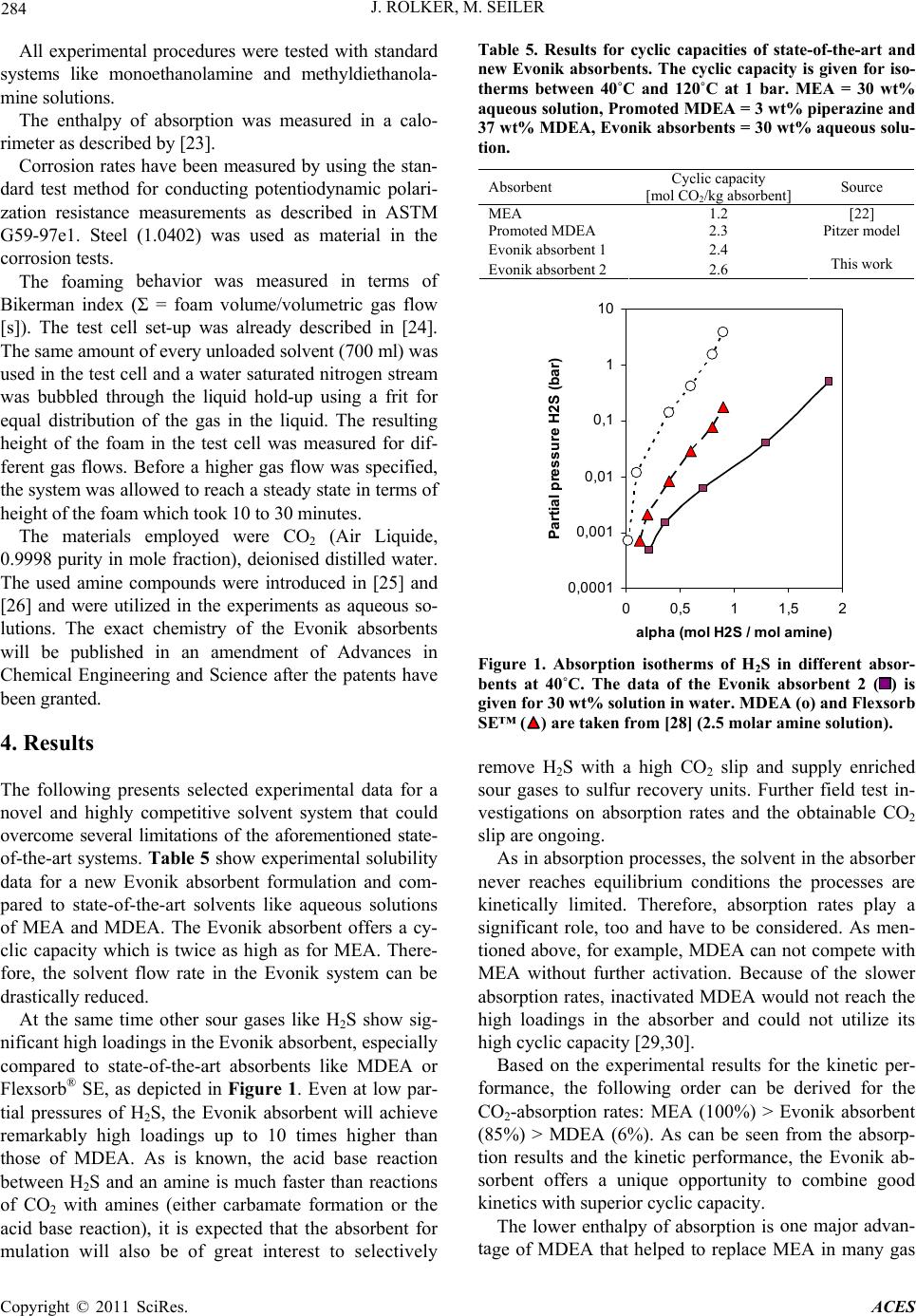 J. ROLKER, M. SEILER 284 ith standard sy f absorption was measured in a calo- rim easured by using the stan- da behavior was measured in terms of B Liquide, 0. . Results he following presents selected experimental data for a her sour gases like H2S show sig- ni Absorbent Cyclic capacity [mo t] Source All experimental procedures were tested w stems like monoethanolamine and methyldiethanola- mine solutions. The enthalpy o eter as described by [23]. Corrosion rates have been m rd test method for conducting potentiodynamic polari- zation resistance measurements as described in ASTM G59-97e1. Steel (1.0402) was used as material in the corrosion tests. The foaming ikerman index (Σ = foam volume/volumetric gas flow [s]). The test cell set-up was already described in [24]. The same amount of every unloaded solvent (700 ml) was used in the test cell and a water saturated nitrogen stream was bubbled through the liquid hold-up using a frit for equal distribution of the gas in the liquid. The resulting height of the foam in the test cell was measured for dif- ferent gas flows. Before a higher gas flow was specified, the system was allowed to reach a steady state in terms of height of the foam which took 10 to 30 minutes. The materials employed were CO2 (Air 9998 purity in mole fraction), deionised distilled water. The used amine compounds were introduced in [25] and [26] and were utilized in the experiments as aqueous so- lutions. The exact chemistry of the Evonik absorbents will be published in an amendment of Advances in Chemical Engineering and Science after the patents have been granted. 4 T novel and highly competitive solvent system that could overcome several limitations of the aforementioned state- of-the-art systems. Table 5 show experimental solubility data for a new Evonik absorbent formulation and com- pared to state-of-the-art solvents like aqueous solutions of MEA and MDEA. The Evonik absorbent offers a cy- clic capacity which is twice as high as for MEA. There- fore, the solvent flow rate in the Evonik system can be drastically reduced. At the same time ot ficant high loadings in the Evonik absorbent, especially compared to state-of-the-art absorbents like MDEA or Flexsorb® SE, as depicted in Figure 1. Even at low par- tial pressures of H2S, the Evonik absorbent will achieve remarkably high loadings up to 10 times higher than those of MDEA. As is known, the acid base reaction between H2S and an amine is much faster than reactions of CO2 with amines (either carbamate formation or the acid base reaction), it is expected that the absorbent for mulation will also be of great interest to selectively Table 5. Results for cyclic capacities of state-of-the-art and new Evonik absorbents. The cyclic capacity is given for iso- therms between 40˚C and 120˚C at 1 bar. MEA = 30 wt% aqueous solution, Promoted MDEA = 3 wt% piperazine and 37 wt% MDEA, Evonik absorbents = 30 wt% aqueous solu- tion. l CO2/kg absorben MEA 1.2 [22] Promoted MDEA Pitzdel2.3 er mo Evonik absorbent 1 2.4 Evonik absorbent 2 2.6 This work 0,0001 0,001 0,01 0,1 1 10 00,511,5 alpha (mol H2S / mol amine) Par tial pressur e H2S (bar ) 2 Figure 1. Absorption isotherms of H2S in differet absor- move H2S with a high CO2 slip and supply enriched n processes, the solvent in the absorber ne esults for the kinetic per- fo one major advan- ta n bents at 40˚C. The data of the Evonik absorbent 2 () is given for 30 wt% solution in water. MDEA (o) and Flexorb SE™ () are taken from [28] (2.5 molar amine solution). s re sour gases to sulfur recovery units. Further field test in- vestigations on absorption rates and the obtainable CO2 slip are ongoing. As in absorptio ver reaches equilibrium conditions the processes are kinetically limited. Therefore, absorption rates play a significant role, too and have to be considered. As men- tioned above, for example, MDEA can not compete with MEA without further activation. Because of the slower absorption rates, inactivated MDEA would not reach the high loadings in the absorber and could not utilize its high cyclic capacity [29,30]. Based on the experimental r rmance, the following order can be derived for the CO2-absorption rates: MEA (100%) > Evonik absorbent (85%) > MDEA (6%). As can be seen from the absorp- tion results and the kinetic performance, the Evonik ab- sorbent offers a unique opportunity to combine good kinetics with superior cyclic capacity. The lower enthalpy of absorption is ge of MDEA that helped to replace MEA in many gas Copyright © 2011 SciRes. ACES  J. ROLKER, M. SEILER 285 quirements as ou nal degrees of freedom from the ch the ne Table 6. Results of the enthalpy of absorption for CO2 in Solvent Enthalpy of absorption Source sweetening applications. The heat of reaction, the physi- cal enthalpy of solution and the excess enthalpy of mix- ing contribute to the enthalpy of absorption. As dis- cussed above this represents a major part of the regen- eration energy that has to be supplied in the stripper. From Table 6 it can be seen that the Evonik absorbent has a considerable lower enthalpy of absorption com- pared to state-of-the-art solvents. This results in further energy savings in the regeneration of the solvent and makes the Evonik absorbent a highly energy-efficient and highly economically attractive alternative to state- of-the-art solvents like MEA and MDEA. The solvent has to fulfill additional re tlined above in order to lower the operational expen- diture of a separation plant. For example one important point is corrosion, which is still a serious issue for ab- sorption plants. The corrosion potential of the Evonik absorbents is much lower compared to uninhibited MEA—by the factor of 7—and compared to Piperazine and MDEA mixtures by a factor of 3.4 (see Table 7). The experiments utilized common carbon steel (1.0402) for plant construction to demonstrate the comparatively low corrosion rates. As a result additio oice of different materials for constructing the plant and the chosen corrosion inhibitor allowing for a reduc- tion in both, capital and operational expenditure. In order to determine the tendency of foaming of w absorbent formulation, the Bikerman index was calculated according to the experimental procedure de- scribed above. The lower the number of the Bikerman index, the less is the foaming height of the system and hence the foaming tendency. Figure 2 plots the Biker- man index for a promoted MDEA (10 wt% Evonik pro- different absorbents at 40˚C. [kJ/mol] ME) A (30 wt%–85 [31] MDEA (50 wt%) –65 [27] Evont%) Th ik absorbent 1 (30 w–30 Evonik absorbent 2 (30 wt%) -- is work Table 7. Corrosion test results from the Potentiodynamic Solvent ion rate Polarization Resistance Measurements with CO2-saturated solutions at 25˚C for typical carbon steel (1.0402). Corros [mm/year] ME) A (30 wt%1.99 MDEA (27.9e (2.1 wt%) wt%) + piperazin0.99 MDEA (37.2 wt%) + piperazine (2.8 wt%) 1.18 Evonik absorbent 1 0.21 Evonik absorbent 2 0.29 0 2 4 6 8 10 12 14 16 18 20 051015 2025 Gas flow [Liter/h] Bikerman i ndex [1/s] Figure 2. Foaming tendency of a promoted MDEA solution oter and 20 wt% MDEA) and the Evonik absorbent 2 wing, results from an estimated process pe and the le (10 wt% Evonik promoter and 20 wt% MDEA) (, ∆) and of Evonik absorbent 2 () without anti foaming agent. The Bikerman index is plotted versus the gas flow rate for dif- ferent test runs at 40˚C. m versus the gas flow rate. It can be concluded that even at higher gas flow rates the Evonik absorbent 2 did not show any tendency to foam which results in a Bikerman index of zero. MDEA is known to cause frequent foam- ing problems in gas sweetening plants and thus indicates a high number for the Bikerman index (approx. 14.5). From various reports in the literature it is well known, that the solution tends to foam, especially at high con- centrations of MDEA [1,32,33]. Our field tests con- firmed that the Evonik absorbent shows no foaming ten- dency, whereas promoted and pure MDEA solutions tended to foaming and needed an anti-foaming agent. Although foaming is a complex matter and basically in- fluenced by various solution contaminants (water-soluble surfactants, liquid hydrocarbons, particles, heat stable salts and a host of others) these encouraging results indi- cate that a common problem of gas treating units might become less of an issue with this new high performance absorbents. In the follo rformance of the Evonik absorbent are derived based on the approach recently introduced by [34]. By means of a modified Kremser equation the absorber and the desorber are described and calculated on a simplified equilibrium stage model that uses isotherms at absorber and desorber temperature and caloric data (heat capacity, absorption enthalpy). The model predicts the minimum reboiler energy at an optimum solvent flow rate for given boundary conditions. The kinetics of absorption are not considered and a sufficient number of equilibrium stages is assumed. The calculation is based on a simplified ab- sorber/desorber flow sheet without a flash, but with in- ternal heat exchanger as illustrated by Figure 3. The feed gas enters the absorber at the bottom, an solvent is fed at the top of the absorber, where the treated gas leaves the column with its CO2 content reduced. Copyright © 2011 SciRes. ACES  286 J. ROLKER, M. SEILER Feed gas Treated gas sour gas AB DB HX1 HX2 HX3 HX4 Feed gas Treated gas AB DB HX1 HX2 HX3 HX4 Figure 3. Simplified process scheme for sour gas absorptio he rich absorbent at absorber bottom is internally pre- re performed for a natural gas and a sy , for natural and for syngas purification, a 90 he specific reboiler duty (GJ/t C ns for the calculation. Para sour gas n utilized for the Kremser method. (AB = Absorber; DB = Desorber; HX1 = Internal heat exchanger; HX2 = Absor- bent cooler; HX3 = Condenser; HX4 = Reboiler). T heated and enters the desorber at the top. The reboiler at the bottom supplies the necessary heat for regeneration which consists of parts for desorption enthalpy, stripping steam, heating of the solvent and heating of the con- densate reflux. The boundary conditions for the calcula- -tions are given in Table 8. Table 9 depicts the neces- sary caloric data. Calculations we ngas feed (see Table 10). As reference system, a mix- ture of piperazine (10 wt%) and MDEA (30 wt%) was chosen for a comparison with the Evonik absorbent (30 wt%). In both cases % CO2 removal was specified to obtain an energetic comparison between the two absorbent systems in terms of specific reboiler duty. In Figures 4 and 5, t O2 separated) is plotted against the corresponding ab- sorbent flow rate to achieve 90% CO2 separation. It can be concluded that in the case of the Evonik absorbent 2, the flow rate can be reduced to 74% (syngas) and 84% (natural gas) compared to the reference system. The spe- cific reboiler duty even decreases to 80% (both cases) for the Evonik absorbent 2 achieving huge savings’s in the reboiler’s steam consumption which directly translates into lower operational expenditures. For the calculation of the natural gas purification, the Evonik absorbent 1 also offers a 16% reduction in absorbent flow rate and a drastic decrease of the specific reboiler duty which amounts to 55% compared to the reference absorbent. For all calculations the superior thermodynamic proper- ties like large cyclic capacities and lower enthalpies of absorption allow for distinctive improvements in terms of an energy efficient process. Table 8. Boundary conditio meter Value CO2 separation degree 90% Absorber inlet temperature mperature 40˚C Desorber inlet temperature 110˚C Desorber pressure 2 bar Desorber bottom te120˚C Equilibrium stages absorber 10 Equilibrium stages desorber 15 Table 9. Caloric data for the calculations for the 10 wt% data Value Piperazine and 30 wt% MDEA mixture and the 30 wt% Evonik absorbent. *Since no heat capacity data was avail- able neither for the piperazine and MDEA mixture nor for the Evonik absorbent, the estimated data from [34] was applied. **The value was taken from [35] and estimated for 110˚C. Caloric Enthalpy of evaporation of water kJ/kg 2210.6 Heat capacity of water 4.197 kJ/kgK* Absorption Enthalpy of 10 wt% Piperazine Evonik 811.2 kJ/kg f 30 wt% Evonik 1817.5 kJ/kg orbents and 30 wt% MDEA at 110 ˚C Absorption Enthalpy of 30 wt% 2236 kJ/kg** absorbent 1 at 110 ˚C Absorption Enthalpy o absorbent 2 at 110 ˚C Heat capacity of all abs4.048 kJ/kgK* Table 10. Natural gas and syngas feed utilized in the calcu- al gas feed Syngas feed lations. Natur 15 mol-% CO2 17 mol-% CO2 1 mol-% H2O 0.3 mol-% CO 5 mol-% N2 60 mol-% H2 79 mol-% CH4 22 4 otal pressure = 10 bar mol-% N2 0.5 mol-% CH 0.2 mol-% Ar TTotal pressure = 36 bar 40% 60% 80% 100% 120% 140% 160% 60% 65% 70% 75% 80% 85% 90%95%100% Absorbent mass flow rate Specific reboiler d ut y Figure 4. Results from calculation of modified Kremser equations for a 90% CO2-separation from a natural gas feed. The specific reboiler duty is plotted against the solvent flow rate for a mixture of piperazine (10 wt%) and MDEA (30 wt%) () and Evonik absorbent 1 (30 wt%) () and for the Evonik absorbent 2 (30 wt%) (). 100% equals 2.68 GJ/t CO2. Copyright © 2011 SciRes. ACES 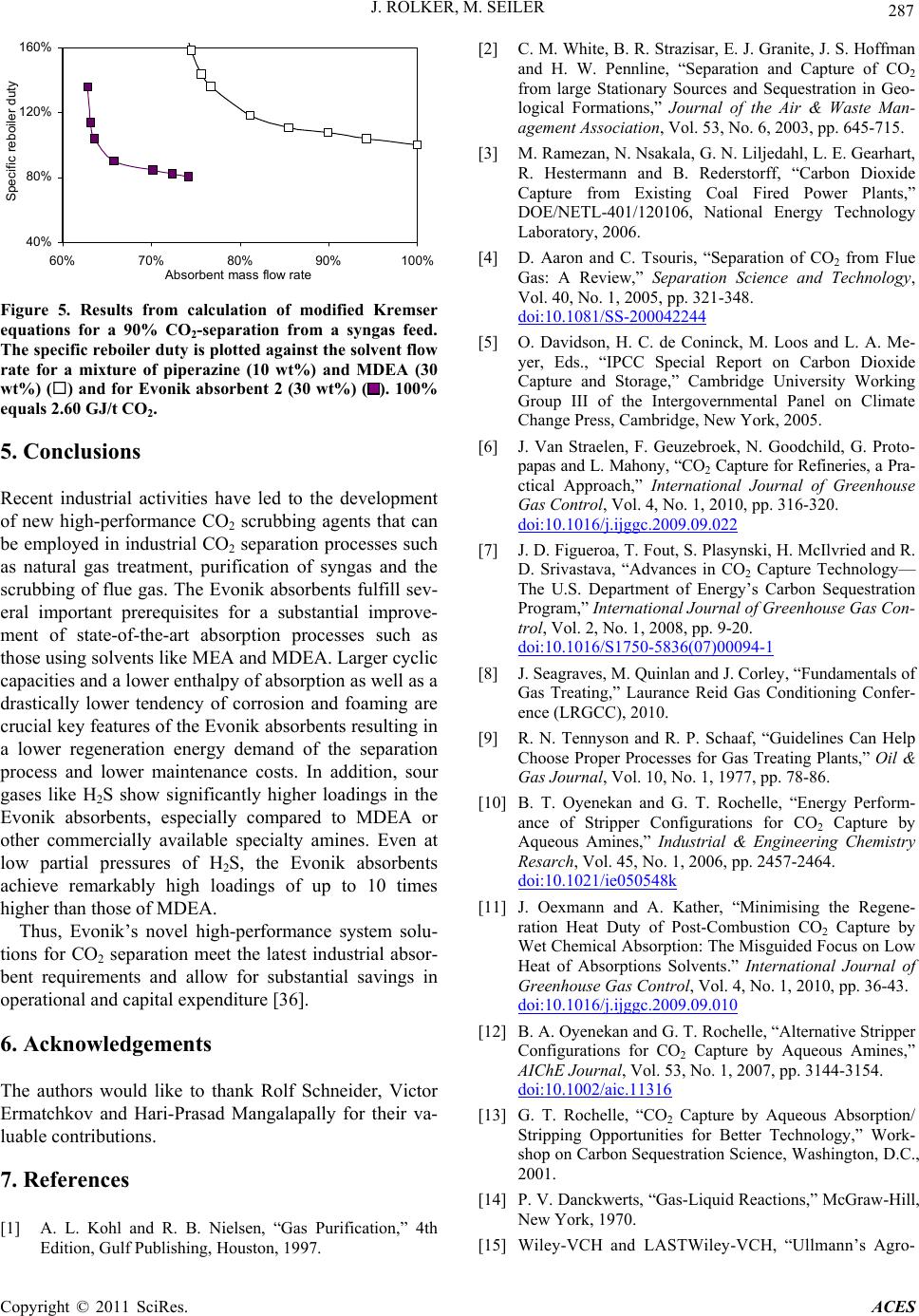 J. ROLKER, M. SEILER 287 40% 80% 120% 160% 60% 70% 80%90%100% Absorbent mass flow rate Specific reboiler duty Figure 5. Results from calculation of modified Kremse ecent industrial activities have led to the development -performance system sol tio he authors would like to thank Rolf Schneider, Victor ] A. L. Kohl and R. B. Nielsen, “Gas Purification,” 4th , J. S. Hoffman ouris, “Separation of CO2 from Flue Gas r equations for a 90% CO2-separation from a syngas feed. The specific reboiler duty is plotted against the solvent flow rate for a mixture of piperazine (10 wt%) and MDEA (30 wt%) () and for Evonik absorbent 2 (30 wt%) (). 100% equals 2.60 GJ/t CO2. 5. Conclusions R of new high-performance CO2 scrubbing agents that can be employed in industrial CO2 separation processes such as natural gas treatment, purification of syngas and the scrubbing of flue gas. The Evonik absorbents fulfill sev- eral important prerequisites for a substantial improve- ment of state-of-the-art absorption processes such as those using solvents like MEA and MDEA. Larger cyclic capacities and a lower enthalpy of absorption as well as a drastically lower tendency of corrosion and foaming are crucial key features of the Evonik absorbents resulting in a lower regeneration energy demand of the separation process and lower maintenance costs. In addition, sour gases like H2S show significantly higher loadings in the Evonik absorbents, especially compared to MDEA or other commercially available specialty amines. Even at low partial pressures of H2S, the Evonik absorbents achieve remarkably high loadings of up to 10 times higher than those of MDEA. Thus, Evonik’s novel highu- ns for CO2 separation meet the latest industrial absor- bent requirements and allow for substantial savings in operational and capital expenditure [36]. 6. Acknowledgements T Ermatchkov and Hari-Prasad Mangalapally for their va- luable contributions. 7. References [1 Edition, Gulf Publishing, Houston, 1997. [2] C. M. White, B. R. Strazisar, E. J. Granite and H. W. Pennline, “Separation and Capture of CO2 from large Stationary Sources and Sequestration in Geo- logical Formations,” Journal of the Air & Waste Man- agement Associatio n, Vol. 53, No. 6, 2003, pp. 645-715. [3] M. Ramezan, N. Nsakala, G. N. Liljedahl, L. E. Gearhart, R. Hestermann and B. Rederstorff, “Carbon Dioxide Capture from Existing Coal Fired Power Plants,” DOE/NETL-401/120106, National Energy Technology Laboratory, 2006. [4] D. Aaron and C. Ts : A Review,” Separation Science and Technology, Vol. 40, No. 1, 2005, pp. 321-348. doi:10.1081/SS-200042244 [5] O. Davidson, H. C. de Coninck, M. Loos and L. A. Me- d, G. Proto- yer, Eds., “IPCC Special Report on Carbon Dioxide Capture and Storage,” Cambridge University Working Group III of the Intergovernmental Panel on Climate Change Press, Cambridge, New York, 2005. [6] J. Van Straelen, F. Geuzebroek, N. Goodchil papas and L. Mahony, “CO2 Capture for Refineries, a Pra- ctical Approach,” International Journal of Greenhouse Gas Control, Vol. 4, No. 1, 2010, pp. 316-320. doi:10.1016/j.ijggc.2009.09.022 [7] J. D. Figueroa, T. Fout, S. Plasynski, H. McIlvried and R. D. Srivastava, “Advances in CO2 Capture Technology— The U.S. Department of Energy’s Carbon Sequestration Program,” International Journal of Greenhouse Gas Con- trol, Vol. 2, No. 1, 2008, pp. 9-20. doi:10.1016/S1750-5836(07)00094-1 [8] J. Seagraves, M. Quinlan and J. Corley, “Fundamentals of P. Schaaf, “Guidelines Can Help Perform- Gas Treating,” Laurance Reid Gas Conditioning Confer- ence (LRGCC), 2010. [9] R. N. Tennyson and R. Choose Proper Processes for Gas Treating Plants,” Oil & Gas Journal, Vol. 10, No. 1, 1977, pp. 78-86. [10] B. T. Oyenekan and G. T. Rochelle, “Energy ance of Stripper Configurations for CO2 Capture by Aqueous Amines,” Industrial & Engineering Chemistry Resarch, Vol. 45, No. 1, 2006, pp. 2457-2464. doi:10.1021/ie050548k [11] J. Oexmann and A. Kather, “Minimising the Regene- ration Heat Duty of Post-Combustion CO2 Capture by Wet Chemical Absorption: The Misguided Focus on Low Heat of Absorptions Solvents.” International Journal of Greenhouse Gas Control, Vol. 4, No. 1, 2010, pp. 36-43. doi:10.1016/j.ijggc.2009.09.010 [12] B. A. Oyenekan and G. T. Rochelle, “Alternative Stripper Configurations for CO2 Capture by Aqueous Amines,” AIChE Journal, Vol. 53, No. 1, 2007, pp. 3144-3154. doi:10.1002/aic.11316 [13] G. T. Rochelle, “CO2 Capture by Aqueous Absorption/ anckwerts, “Gas-Liquid Reactions,” McGraw-Hill, ASTWiley-VCH, “Ullmann’s Agro- Stripping Opportunities for Better Technology,” Work- shop on Carbon Sequestration Science, Washington, D.C., 2001. [14] P. V. D New York, 1970. [15] Wiley-VCH and L Copyright © 2011 SciRes. ACES  J. ROLKER, M. SEILER Copyright © 2011 SciRes. ACES 288 - chemicals,” Vol. 1, Wiley-VCH, Weinheim, 2007. [16] G. Sartori and D. W. Savage, “Sterically Hindered Ami nes for CO2 Removal from Gases,” Industrial & Engi- neering Chemistry Fundamentals, Vol. 22, No. 1, 1983, pp. 239-249. doi:10.1021/i100010a016 [17] J.-Y. Park, S. J. Yoon and H. Lee, “Effect of Steric Hin- drance on Carbon Dioxide Absorption into New Amine Solutions: Thermodynamic and Spectroscopic Verifica- tion through Solubility and NMR Analysis,” Environ- mental Science & Technology, Vol. 37, No. 1, 2003, pp. 1670-1675. doi:10.1021/es0260519 [18] F. Bougie and M. C. Iliuta, “Analysis of Regeneration of Sterically Hindered Alkanolamines Aqueous Solutions with and without Activator,” Chemical Engineering Sci- ence, Vol. 65, No. 1, 2010, pp. 4746-4750. doi:10.1016/j.ces.2010.05.021 [19] R. G. F. Albry and M. S. DuPart, “Amine Plant Trouble- “Solubility of CO in Aqueous Shooting and Optimization,” Gulf Publishing Co., Hous- ton, April 1995, pp. 3-11. [20] K. P. Shen and M.-H. Li, 2 Mixtures of Monoethanolamine with Methyldiethanola- mine,” Journal of Chemical Engineering Data, Vol. 37, No. 1, 1992, pp. 96-100. doi:10.1021/je00005a025 [21] O. F. Dawodu and A. Meisen, “Solubility of Carbon Di- oxide in Aqueous Mixtures of Alkanoamines,” Journal of Chemical Engineering Data, Vol. 39, No. 1, 1994, pp. 548-552. doi:10.1021/je00015a034 [22] F.-Y. Jou, A. E. Mather and F. E. Otto, “The Solubility of CO2 in a 30 Mass Percent Monoethanolamine Solution,” Canadian Journal of Chemical Engineering, Vol. 73, No. 1, 1995, pp.140-145. doi:10.1002/cjce.5450730116 [23] J. Gmehling, “Excess Enthalpies for 1,1,1-Trichloroethane with Alkanes, Ketones, and Esters,” Journal of Chemical Engineering Data, Vol. 38, No. 1, 1993, pp. 143-146. doi:10.1021/je00009a036 [24] G. Senger and G. Wozny, “Experimentelle Untersuchung von Schaum in Packungskolonnen,” Chemie Ingenieur Technik, Vol. 83, No. 4, 2011, pp. 503-510. doi:10.1002/cite.201000210 [25] M. Seiler and J. Rolker, “Verfahren, Absorptionsmedien r and F. E. Otto, “Solubility of H2S und Vorrichtung zur Absorption von CO2 aus Gasmis- chungen,” Evonik Degussa, PCT/EP 2010/051083, 2010. [26] M. Seiler and J. Rolker, “Verfahren zur Absorption von sauren Gasen aus Gasgemischen,” Evonik Degussa, 2010, DE 102010043838.3. [27] F.-Y. Jou, A. E. Mathe and CO2 in Aqueous Methyldiethanolamine Solutions,” Industrial Engineering Chemistry Process Design and Development, Vol. 21, No. 1, 1982, pp. 539-544. doi:10.1021/i200019a001 [28] T. R. Aikins, L. E. Parks, J. N. Iyengar, R. B. Fedich and Ki- D. Perry, “Sterically Hindered Amines-Thirty Years of Gas Treating Practice,” Annual Laurance Reid Gas Con- ditioning Conference, Norman, 20-23 February 2011. [29] G. W. Xu, C.-F. Zhang, S.-J. Qin and Y.-W. Wang, “ netics Study on Absorption of Carbon Dioxide into Solu- tions of Activated Methyldiethanolamine,” Industrial & Engineering Chemistry Resesrch, Vol. 31, No. 1, 1992, pp. 921-927. doi:10.1021/ie00003a038 [30] P. W. J. Derks, “Carbon Dioxide Absorption in Pipera- , “Vapor-Liquid zine Activated n-Methyldiethanolamine,” Ph.D. Thesis, University of Twente, Nederland, 2006. [31] F.-Y. Jou, F.-E. Otto and A. E. Mather Equlibrium of Carbon Dioxide in Aqueous Mixtures of Monoethanolamine and Methyldiethanolamine,” Indus- trial & Engineering Chemistry Resesrch, Vol. 33, No. 1, 1994, pp. 2002-2005. doi:10.1021/ie00032a016 [32] J. Seagraves and R. H. Weiland, “Treating High CO2 and S. T. Donnelly, “The Use . P. Mangalapally, S. Hoch and H. Gases with MDEA,” Petroleum Technology Quarterly GAS, 2009, pp. 103-109. [33] J. A. Bullin, J. C. Polasek of MDEA and Mixtures of Amines for Bulk CO2 Re- moval,” Bryan Research & Engineering, Inc., 2006. http://www.bre.com [34] R. Notz, I. Tönnies, H Hasse, “A Short-Cutmethod for Assessing Absorbents for Post-Combustion Carbon Dioxide Capture,” International Journal of Greenhouse Gas Control, Vol. 5, No. 3, 2010, pp. 413-421. doi:10.1016/j.ijggc.2010.03.008 [35] B. Schäfer, A. E. Mather and K. N. Marsh, “Enthalpies of Solution of Carbon Dioxide in Mixed Solvents,” Fluid Phase Equilibria, Vol. 194-197, 2002, pp. 929-935. doi:10.1016/S0378-3812(01)00722-1 [36] J. Rolker and M. Seiler, “Elements 37,” Quaterly Science Newsletter, Vol. 4, 2011.
|