Communications and Network
Vol.3 No.4(2011), Article ID:8470,7 pages DOI:10.4236/cn.2011.34029
Fast Handoff for 802.11 Wireless Network
1Department of Computer Systems and Technology, Faculty of Computer Science and Information Technology, University of Malaya, Kuala Lumpur, Malaysia
2Electrical Engineering Department, College of Engineering, University of Mosul, Mosul, Iraq
E-mail: obaysabrie@yahoo.com
Received September 4, 2011; revised October 19, 2011; accepted October 28, 2011
Keywords: Handoff Delay, IEEE 802.11, Layer 2 Handoff, WLAN
Abstract
Whenever the mobile station moves from the range of one access point and comes to the range of another access point a handoff process is occurred. This process takes a long time when using the IEEE 802.11 standard handoff and this delay affect the real time and multimedia applications. This paper provides a layer 2 handoff process for the IEEE 802.11 that is able to eliminate the scanning delay and reduce the total handoff delay.
1. Introduction
Even with the great benefits and easy of use provided by IEEE 802.11, there are some problems that need to be solved. One of the most important problems is the handoff process delay. This delay time affects the applications used by the mobile station (STA) during the handoff process. The handoff process occurs when the STA moves from the range of one access point (AP) to the range of another AP. During this process some management information related to the STA need to be transferred between the old AP and new AP through IAPP or other protocols. The layer 2 handoff process occurs between APs within the same IP subnet. There are three handoff delays in the IEEE 802.11 standard handoff process, which are scanning delay, re-authentication delay and re-association delay [1].
1) Scanning Phase Delay The scanning phase delay represents the time taken by the STA to scan all the WLAN channels in order to find the best AP after the handoff process is triggered using a specific threshold (TH) [2].There is two scanning types [3]:
a) Passive scan;
b) Active scan.
Passive scan: means that the STA listen to the beacon messages broadcasted periodically by the APs.
Beacon message contains necessary information like BSSID, beacon interval, support rate, etc. This information is used by the STA in order to select the best available AP. In addition, the STA using passive scan must wait for a duration called Max channel time on each channel to collect all the beacon messages sent by different APs. After scanning all channels the beacons will be processed and the best AP will be selected [4]. The passive scan increases the handoff delay time because the STA has to scan all the available channels. On the other hand, using the passive scan reduces the power and bandwidth consumption [5].
Active scan: means that the STA broadcast a probe requests on each channel to be scanned and wait for a probe response from all reachable access points (APs). The STA waits for a period of time for the probe responses called the Min channel time. If no response or traffic detected from any AP then the channel is assumed to be empty and the STA switches to the next channel. Otherwise, if a probe response is detected then, the STA assumes that at least one AP may exist and wait at the same channel until the Max channel time expires, in order to give time for other APs responses to be received [6]. The active scan can reduce the STA waiting time, but on the other hand it increases the power and bandwidth consumption [7]. The scanning delay represents almost 90% of the total handoff delay [1,8].
2) Re-authentication Phase Delay
The re-authentication phase delay is the time taken to authenticate the STA with the new AP. There are two types of authentication provided in [3].
a) Open system authentication;
b) Shared key authentication.
The re-authentication delay depends on the authentication method used. During the open system authentication only two messages are exchanged. The STA send a re-authentication request to the new AP and then, receive a re-authentication response. Otherwise, if the shared key authentication is used then, four messages must be used to exchange the information between the STA and the new AP. The additional messages are used to create the shared key.
3) Re-association Phase Delay
The re-association phase delay is the time taken to re-association the STA with the new AP. The STA send a re-association request to the new AP and wait for a re-association response [1]. During this process the new AP requests the STA context information from the old AP using IAPP before sending the re-association response [2].
1.1. Inter Access Point Protocol (IAPP)
The main reason behind developing the inter access point protocol (IAPP) was to transfer state and context information of the STA between APs during the handoff process [4]. The IAPP transfer the context information from the old AP to the new AP through the distribution system (DS), in order to provide more reliable and secure connection (better than wireless connection (air)) to exchange context information between APs [2].
The following steps explain how the IAPP packets are exchanged:
1) The STA send a re-association request to the new AP.
2) The new AP receive the re-association request (from the STA) and send MOVE-notify packet to the old AP (i.e. AP the STA was connected to) to inform it that the STA request for a re-association.
3) The old AP receive the MOVE-notify packet from the new AP and responds by sending the STA context information using MOVE-response packet to the new AP then, disassociate the STA.
4) After the new AP receives the STA context information from the old AP, it (i.e. new AP) sends a re-association response to the STA.
Context information may contain security context, BSSID, sequence number, time stamp, quality of service (QoS), header compression and accounting, etc. [8]. For additional security the new AP can Send-Security-Block packet before the MOVE-notify packet to the old AP. Then, the old AP responds by sending ACK-SecurityBlock packet to establish a secure connection between the APs. Table 1 shows inter access point protocol (IAPP) modified packet.
In addition, IAPP makes sure that the STA maintain a unique association to the wireless network. Whenever the STA associate to a new AP, that AP broadcast an ADD-notify packet to all APs in the network to inform them about the STA association. After receiving the ADD-notify packet all other APs discard and clear state information for the STA to ensure a unique association for the STA to the network. Table1 shows inter access point protocol (IAPP) modified packet.

Table 1. Inter access point protocol (IAPP) modified packet.
1.2. Caching Techniques in Handoff Process
Caching in handoff process means, storing the network topology (i.e. APs location) and APs information like AP MAC address, AP channel number, authentication information, context information, etc. to provide fast access for the STA to the necessary information needed during the handoff process. When the cache is used in handoff process it reduces the total handoff delay time. The cache can be stored in three locations (Server, AP and STA) [9]. Whenever the cache is stored inside the server it’s called centralized and the server will be responsible for providing the topology information for the STA [10]. However, when a server failure occurred the STA cannot receive any information from it and the STA should use the standard handoff method. If the cache is stored inside the APs it’s called distributed because the topology information is distributed inside all the APs composing the network. The distributed caching can reduce the chance of a single point failure and prevent the network collapse. There are two types of neighbors caching:
1) Static;
2) Dynamic.
Static neighbors caching means that the network topology information is produced once and never change during the operations. However, providing static neighbors location in WLAN is not easy because the relationship between APs is not fixed. The instability of radio coverage caused by different barriers such as interference, walls, furniture and moved objects [11]. Thus, the static neighbors caching fails to support the dynamic networks which changes over time.
Dynamic neighbors caching means that the network topology information is produced and can be update during the operations according to the changes or failures in the network topology. The dynamic caching provides better support for mobility.
2. Methods
The method goal is to provide the STA with the next possible AP in order to eliminate the scanning delay. The STA can send the currently associated AP address and channel number inside the probe request during the scanning phase [12]. The STA send the probe request then switch to another channel without waiting for the response. The method proposed in this paper use the information sent from the STA inside the probe request (current AP address and channel number) and stores it inside a neighbors table in all the APs that have received the probe request. In additions, the neighboring APs information like BSSID, beacon interval, support rate, channel number, etc. is transferred from the APs received the probe request to the currently associated AP using the newly proposed IAPP neighbors update packet shown in Table 2. This will update the currently associated AP and the probed APs.
Whenever the currently associated AP receives the packet from another AP it checks whether the AP information is already exists inside its neighbors table or not. If the AP information is not in its table the currently associated AP stores the received AP information into its neighbors table. Otherwise, if the AP already exists inside the neighbors table then nothing is changed inside the table. Figure 1 shows the AP receives probe request from STA flowchart.

Table 2. Neighbors update packet body.
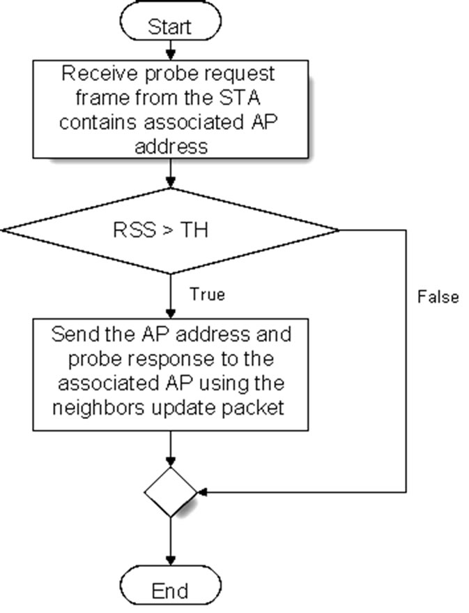
Figure 1. AP receives probe request from STA flow chart.
In order to make sure that only the neighboring APs are responding to the STA probe with a neighbors update packet a threshold (TH) is added to the APs. The probe request strength or what is called received signal strength (RSS) must be more than the specified TH to allow the AP to respond and send its information to the currently associated AP. Figure 2 shows the AP receives IAPP neighbors update packet flow chart.
The currently associated AP copy the contents of its neighbors table to the beacon frames and send it to the STAs [9]. When the STA receives a beacon frame with a neighbors table it stores that table as a STA neighbors table and when the STA moves away from the currently associated AP and a handoff is needed, the STA use the STA neighbors table to authenticate directly with the first AP available inside the table without scanning. If the first AP does not respond to the authentication request from the STA that means it is not available. Therefore, the STA tries to authenticate with the second AP inside the neighbors table.
However, if the STA was not able to authenticate with any of the APs inside the table then the STA will perform a full scanning (i.e. IEEE802.11 standard) [3]. Figure 3 shows the STA connecting to a new AP flow chart.

Figure 2. AP receives IAPP neighbors update packet flow chart.

Figure 3. STA connecting to a new AP flow chart.
3. Results
The OMNeT++ simulation results shows a significant improvement in the handoff process when the STA is provided with a table of the next possible APs. The STA start using the neighbors table when a handoff is needed and tries to connect with the first AP inside the table directly without active or passive scanning. If the first AP is not responding then the STA tries to connect to the second AP inside the neighbors table and so on until an AP respond. Providing the next possible APs to the STA bring the total handoff delay down from an average of 300 - 400 ms in IEEE 802.11 standard [3] to an average of 2 - 3 ms using the fast handoff as shown in Figure 4. The best time was when the first AP inside the neighbors table is available and the worst case was when the available AP is the last AP inside the neighbors table. The authentication method used during the simulation was

Figure 4. Handoff delays using direct connection.

Table 3. General simulation settings for the STA and APs.
open system authentication and the association was direct with one association request and one association response to connect the STA. Table 3 shows general simulation settings for the STA and APs during simulation.
4. Discussion
The handoff delay is caused mainly by the scanning delay which is about 90%, when the handoff process starts, the STA should scan all channels searching for APs in its range [1,7]. This operation forces the STA to search the channel even if it’s empty. Thus, selective scan was proposed to allow the STA to scan only the non overlapping channels in order to reduce the scanning delay time [13]. Most of the researches that use the selective scan try to combine it with other techniques to provide better results. Furthermore, the scanning delay can be significantly reduced if the STA knows which AP to probe directly using the neighbor graphs (NG) to provide the locations of the APs in the network making it easier for the STA to find the best neighboring AP to connect to. In [6,14] they use the selective active scanning techniques combined with caching and was able to reduce handoff delay by reducing the number of scanned channels. In order to go further they use a caching table located inside the STA. The table contains information of the currently associated AP and if possible other neighboring APs. When a handoff is needed the STA check the caching table and try to associate directly with the first AP in the table and if the re-association unsuccessful, the STA tries to re-associate to the second AP. Otherwise, if the caching table is empty a selective scan will be used to search for APs. The selective scan proved to be effective in reducing the scanning delay.
However, storing the caching table inside a specific STA limits its effect (i.e. each STAs must build their own caching table). Furthermore the STA has to follow the same moving path when it enters the network range again in order to guarantee a high cache hit value. Otherwise, the cache hit value will be low and the STA spend more time trying to re-associate to unavailable APs.
The STA may choose the first AP found during the selective scanning with received signal strength (RSS) more than a specified threshold (TH) value [13]. Then, the STA stop scanning and connect to it (i.e. the new AP) [15]. This method reduces the number of channels scanned and as a result the scanning delay. Nevertheless, the scanning delay varies depending on the number of channels scanned until the AP with the specified RSS received. In some cases, the AP that met the specified TH value is on the last channel scanned. Thus, the method fails to reduce the scanning delay. In addition, the first AP that met the specified TH is not necessary to be the best AP in the STA range.
The NG can be provided using a server to save the network topology as used by [16]. However, using centralized server to save the static NG files means that any server failure or topology change occurred without updating the NG server files may cause a failure and push the STA to use a standard scanning method causing more handoff delay. A method to reduce the scanning delay depending on the communication between the STAs was provided by [17]. In this method the STA buffers a report contain the location of the AP and the RSS in addition to other necessary information. This buffered information is called AP report. The STA broadcast (i.e. send) this AP report on all channels one by one to all other STAs in its range. If the channel is busy then the STA skip it and continue with other channels to reduce delay. After finishing all channels the STA check the busy channels again to broadcast the AP report. If the channels still busy for the second time then the STA discard it. In order to receive the AP report the receiving STA must be within the range of the broadcasting STA [17]. Whenever the STA receives more than one AP report it should decide which one (i.e. AP report) to use depending on the information received like the AP location and RSS. The STA can predicate when the connection can be established and estimate the AP range so it can broadcast the AP report to other STAs before exiting the range and start handoff to the new AP. This method reduces the scanning delay but it suffers from a broadcast delay that may have less impact on the total handoff delay than the standard handoff. As a result the method cannot support VoIP applications efficiently.
The IAPP was developed to be used in order to transfer context information between APs to reduce the reassociation delay [8]. However, in [12] they propose a method that uses the IAPP in order to reduce the scanning delay. In this method the STA probe all channels to search for APs in range. Then, instead of waiting for the response from each AP for a Min channel time (i.e. like the standard situation); all the probed APs send their probe responses using IAPP to the currently associated AP (i.e. where the STA are currently connected) and the STA receives the probe responses from its currently associated AP.
Even if this method can reduce handoff delay but it’s not suitable for the real time and multimedia applications. This is because the STA still has to scan all channels. As a result we extend the work to exchange the neighboring information between APs using IAPP neighbors update packet to build the neighbors table. This table is send to the STA using the beacon frame in order to provide the STA with the next possible AP and eliminate the scanning delay.
5. Conclusions
Fast handoff method used in this article was able to decrease the total handoff time dramatically. The STA sends the probe request and switch to the second channel directly without waiting for the probe response which decrease the handoff time delay. The probe request sent by the STA includes the currently associated AP credentials and the probed AP stores this information inside its neighbors table and responds by a probe response to the currently associated AP (The AP respond to the probe request only if the probe request signal strength is more that the received signal strength RSS threshold). The probe response contains the probed AP information that is used by the currently associated AP to build its neighbors table. APs includes its neighbors table inside the beacon frames sent periodically to the STA and this table is used by the STA when a handoff is needed to connect directly to the next possible AP without the scanning phase. Eliminating the scanning phase drops the total handoff delay time from 300 - 400 ms in IEEE 802.11 [3] standard to 2 - 3 ms and supports the VoIP and multimedia applications requirements. In additions, this method is flexible to the network topology changes because it can update the APs locations.
6. References
[1] D. Murray, M. Dixon and T. Koziniec, “Scanning Delays in 802.11 Networks,” The 2007 International Conference on Next Generation Mobile Applications, Services and Technologies, Cardiff, 2007, pp. 255-260. doi:10.1109/NGMAST.2007.4343430
[2] A. Mishra, M. Shin and W. A. Arbaush, “Context Caching Using Neighbor Graphs for Fast Handoffs in a Wireless Network,” 23rd Annual Joint Conference of the IEEE Computer and Communications Societies, INFOCOM 2004, Hongkong, 2004, p. 361. doi:10.1109/INFCOM.2004.1354508
[3] IEEE 802.11, “IEEE Standard for Information Technology Telecommunications and Information Exchange between Systems Local and Metropolitan Area Networks Specific Requirements,” The Institute of Electrical and Electronics Engineers, New York, 2007.
[4] P.-J. Huang, Y.-C. Tseng and K.-C. Tsai, “A Fast Handoff Mechanism for IEEE 802.11 and IAPP Networks,” Proceedings of 63rd IEEE Vehicular Technology Conference, Melbourne, 2006, pp. 966-970. doi:10.1109/VETECS.2006.1682968
[5] S. Pack, J. Choi, T. Kwon and Y. Choi, “Fast Handoff Support in IEEE 802.11 Wireless Networks,” IEEE Communications Surveys, Vol. 9, No. 1, 2007, pp. 2-12.
[6] S. Sangho, G. F. Andrea, R. A. Singh and S. Henning, “Reducing MAC Layer Handoff Latency in IEEE 802.11 Wireless LANs,” Proceedings of the Second International Workshop on Mobility Management\& Wireless Access Protocols, Philadelphia, 2004, p. 19. doi:10.1145/1023783.1023788
[7] Y. M. Allawi, K. Min-Gon and K. Minho, “Advanced Handoff Mechanism for Delay Sensitive Applications in IEEE 802.11 Wireless LAN,” 10th International Conference on Advanced Communication Technology, Gangwon-Do, 17-20 February 2008, pp. 1517-1520. doi:10.1109/ICACT.2008.4494067
[8] A. Mishra, M. Shin and W. Arbaugh, “An Empirical Analysis of the IEEE 802.11 MAC Layer Handoff Process,” ACM, Vol. 33, No. 2, 2003, p. 93. doi:10.1145/956981.956990
[9] O. H. Sabrie and R. Salleh, “Enhancing Handoff Process Using IAPP with Caching Techniques,” Journal of Applied Sciences, 2009, Vol. 9, No. 22, pp. 3999-4005. doi:10.3923/jas.2009.3999.4005
[10] C.-C. Tseng, K.-H. Chi, M.-D. Hsieh and H.-H. Chang, “Location-Based Fast Handoff for 802.11 Networks,” IEEE Communications Letters, Vol. 9, No. 4, 2005, pp. 304-306.
[11] S. Minho, M. Arunesh and A. A. William, “Improving the Latency of 802.11 Hand-offs Using Neighbor Graphs,” Proceedings of the 2nd International Conference on Mobile Systems, Applications, and Services, ACM, Boston, 2004, pp. 70-83. doi:10.1145/990064.990076
[12] V. M. Chintala and Z. Qing-An, “Novel MAC Layer Handoff Schemes for IEEE 802.11 Wireless LANs,” Wireless Communications and Networking Conference, IEEE, Kowloon, 2007, pp. 4435-4440. doi:10.1109/WCNC.2007.808
[13] IEEE 802.11F, “IEEE Trial-Use Recommended Practice for Multi-Vendor Access Point Interoperability via an Inter-Access Point Protocol Across Distribution Systems Supporting IEEE 802.11™ Operation,” The Institute of Electrical and Electronics Engineers, New York, 2003.
[14] O. Jaeouk, M. Pedro and M. Hiroyuki, “Replacing Channel Scanning with Multiple Authentication for Fast Handoff in IEEE 802.11 Wireless Networks,” Proceedings of the 2007 ACM CoNEXT Conference, New York, 2007, Article No: 40.
[15] L. J. Zhang and S. Pierre, “Optimizing the Performance of Handoff Management in Wireless LANs,” International Journal of Computer Science and Network Security, Vol. 8, No. 7, 2008, pp. 87-94.
[16] H.-S. Kim, S.-H. Park, C.-S. Park, J.-W. Kim and S.-J. Ko, “Selective Channel Scanning for Fast Handoff in Wireless LAN Using Neighbor Graph,” Proceedings of the 2004 International Technical Conference on Circuits/Systems, Computers and Communications (ITCCSCC 2004), Vol. 3260/2004, 2004, pp. 1-4. doi:10.1007/978-3-540-30199-8_16
[17] K. Daehan, S. Junho, K. Seungwoon and M. Jeonghoon, ‘Reducing the Channel Scanning Latency for Intermittently Connected IEEE 802.11 Networks in Vehicular Environments,” Vehicular Technology Conference, IEEE, Singapore, 2008, pp. 3072-3076. doi:10.1109/VETECS.2008.334