World Journal of Engineering and Technology
Vol.04 No.03(2016), Article ID:71319,7 pages
10.4236/wjet.2016.43D002
Research of Magnetic Bias Control System Based on STATCOM
Zongqiang Zheng
NARI Technology Development Co., Ltd., Nanjing, China


Received: May 30, 2016; Accepted: October 13, 2016; Published: October 20, 2016
ABSTRACT
As the most important style of reactive power compensation system, the research and design control system of static synchronous compensator (STATCOM) is an important aspect of keeping stable and normal operation. This paper analyzes the influences of bias magnetic to STATCOM, and proposes an effective magnetic bias control method and program realization, so reduced to producing two harmonics. It improves the quality and reliability of STATCOM output voltage; Finally, the tests are conducted in the ±500 kVar STATCOM, and the results show the validity and necessity of this compensation method.
Keywords:
Static Synchronous Compensator (STATCOM), Magnetic Bias Control, Harmonic Suppression

1. Introduction
With the rapid development of power electronic devices, the introduction of the concept that flexible AC transmission system (FACTS) and user power (CUSTOM POWER) in electric power system [1]-[3]. It is the result of the application and development trend of power electronic technology in power system. Static synchronous compensator (STATCOM) is one of the most important devices. It is a new static var compensation device which can adjust reactive power rapidly and continuously in two directions. Not only it has the great improving the system stability advantage, but also increases the transmission capacity of lines and suppresses voltage flicker etc [4]-[6].
At present, both domestic and international have developed multiple different capacity of STATCOM, and some of which have been put into the power system, but there are different in the design of the main circuit and control method. Among them, the design of main circuit and control method has a very important role, which in improving the performance and the safety and stability of STATCOM. The effect of bias on transformer is analyzed by [7], and the measures to limit the magnetic bias are given, but no concrete realization method is given. Through direct processing of modulation wave digital pulse processing based on magnetic bias suppression method is proposed by [8], and used in the prototype of 3kW single-phase photovoltaic inverter, and achieved good results.
Firstly, this paper introduces the system configuration of the device and the causes of magnetic bias in operation; Secondly, the analysis of bias effects and the consequences of which may bring to the STATCOM. Finally, this paper puts forward a kind of effective control of partial magnetic method and its software implementation. Through simulation test on ±500 kVar of STATCOM, it shows that the method can effectively inhibit the partial magnetic, thus greatly reduces the content of the second harmonic and improves the operation reliability output voltage quality of the STATCOM.
2. System Structure and Inverter Topology
±500 kVar STATCOM device mainly comprises two parts of hardware and software, the hardware structure diagram as shown in Figure 1, it can be seen from the graph, the system is mainly composed of two three-level inverter bridge (TLI1, TLI2), the upper and the lower capacitor group, a three-phase three winding split transformer, the controller and the protection and auxiliary unit. The hardware part in addition to completion of energy transformation, it has protection function. But adjusting and controlling function of ±500 kVar STATCOM is mainly realized by software, according to different site requirements to select the software module. The double inverter bridge through the split transformer connects to the system structure more conducive to improve STATCOM output voltage and current values of THD. For example, 5, 7, 17, 19 6n ±1 (n = 1, 3, 5…), etc. power harmonics can be eliminated by splitting the transformer, but does not affect the fundamental value.
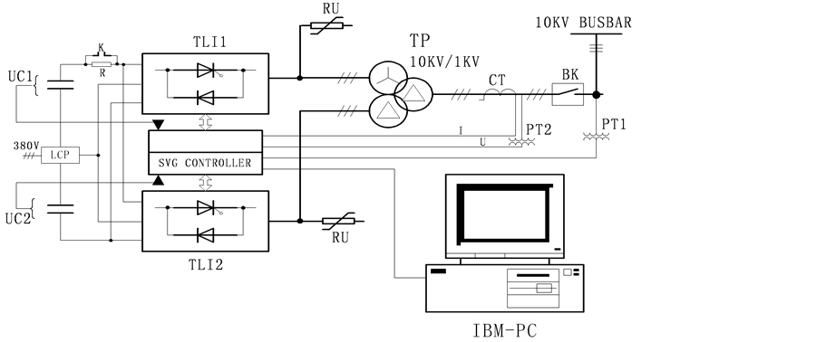
Figure 1. The system structure diagram of ±500 KVA STATCOM.
Among them, three-level inverter (TLI1, TLI2) topology diagram as shown in Figure 2, each phase of three-level inverter has four directional components in the diagram (such as the A phase of S11, S12, S13, S14), two clamping diodes D11, D12 and four anti parallel diodes D1, D2, D3, D4.The three-level inverter is compared with the conventional two level inverter, it has advantages that small output harmonic and improving the voltage level of STATCOM.
It can be seen from the chart, the topological structure of the three-level inverter connects to the upper and lower two capacitors, in order to ensure the upper and lower half wave of inverter output voltage full symmetry, the voltage of upper and lower two capacitor must be equal, otherwise, not only will make the output voltage of STATCOM contains larger two harmonic, at the same time, serious asymmetric voltage of the upper and the lower capacitor, not only will also increase the reverse voltage of the element, but also endanger the safety operation of the element.
3. The Reason and Influence of Magnetic Bias
As mentioned earlier, in order to ensure the full symmetry of inverter output voltage on half wave, the voltage of the upper and lower two capacitors must be equal. However, in actual operation, because of various reasons, it is not balanced, the reasons on the capacitors voltage is not balanced as following:
1) The upper and lower capacitor capacitance value is not exactly the same.
2) The discharge resistance and capacitance in parallel with capacitor are unequal.
3) The dispersion that each switch element and absorption circuit parameter of three-level inverter.
4) The control circuit of the synchronous signal of positive and negative half wave asymmetry etc.
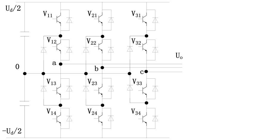
Figure 2. The main circuit structure of three-level inverter.
The voltage imbalance of under and lower capacitor will make the upper and lower half wave output voltage of STATCOM be asymmetry, thereby causing the STATCOM output transformer occurs magnetic bias or DC magnetization. Transformer magnetizing will easily make the transformer get into saturation, in the one bias side current will increase rapidly, on the other side, due to the saturation of the current waveform distortion, so that the STATCOM output voltage and current contains a large number of harmonics, and ultimately lead to STATCOM stop running. Therefore, we must control voltage of the upper and lower capacitor, so then suppress generation of magnetic bias.
4. The Control Strategy and Program Realization of Suppression Magnetic Bias
4.1. Control Method
Here is a simple and feasible method of suppression harmonic, the basic principle is as follows Figure 3.
Taking a single phase as an example, as shown in Figure 3.1, the general pulse generator output PWM wave which upper and lower half wave is symmetric, does not contain even harmonics. In order to produce the even harmonics, it can control the PWM wave which upper and lower half wave toward the same direction (Figure 3.2) or reversed direction (Figure 3.3) to move. The size of the even harmonics is relevant to the movement amount of Δδ.
When δ + Δδ > δ, upper and lower half wave of PWM toward the same direction to move, it makes the upper capacitor voltage UC1 be decreased, under capacitor voltage UC2 be increased. On the contrary, When δ − Δδ < δ, it will make the upper capacitor voltage UC1 be increased, under capacitor voltage UC2 be decreased.
4.2. Program Realization
The controller of ±500 kVar STATCOM is intelligent controller as the core of the digital signal processor (DSP) and field programmable gate array (FPGA). Among them,

Figure 3. The control waveform figure of generating even harmonic.
DSP is responsible for the various operations and monitoring functions, the FPGA and related components consist of pulse generator. Therefore, in achieve the controlling of the magnetic bias, mainly by the DSP to complete detection of the upper and lower capacitor voltage, the PID regulates calculation and controls the output to FPGA, and FPGA according to the correspond synchronous signal to generate PWM wave.
Due to the positive zero crossing point of each phase positive half wave according to the phase synchronization signal, the negative half wave is generated by the zero crossing point of the PWM.DSP must instantaneously detect the state of synchronization signal, and send the results to FPGA.
The capacitor voltage UC2 is greater thanUC1, PID calculates results Δδ is negative, when the synchronization signal is positive zero crossings, δ(n) = δ(n − 1) + Δδ(less than δ(n − 1)); when the synchronous signal is negative zero crossings point, δ(n) = δ(n − 1) − Δδ(more than δ(n − 1)). The result makes the control waveform in the opposite direction, so that the upper capacitor voltage UC1 increases, the under capacitor voltage UC2 decreases, the adjustment process is stopped until reaching a balance steady state between the two capacitors.
On the contrary, the capacitor voltage UC2 is less than the capacitance voltage UC1, PID calculates results Δδ is positive, when the synchronization signal is positive zero crossings, δ(n) = δ(n − 1) + Δδ(more than δ(n − 1)), when the synchronous signal is negative zero crossings, δ(n) = δ(n − 1) −Δδ (less than δ(n − 1)). The result makes the control waveform in the opposite direction, so that the upper capacitor voltage UC1 decreases, the under capacitor voltage UC2 increases, the adjustment process is stopped until reaching a balance steady state between the two capacitors.
5. Simulation Analysis
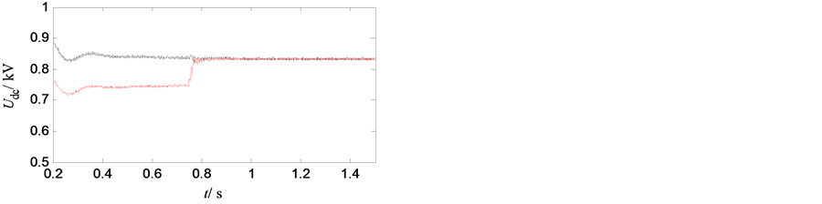
The feasibility of the proposed control strategy is verified by a simulation model which is consistent with the field operation in PSCAD. The effective value of the line voltage is 1000 V. On the DC side, the upper capacitance is 1950 μF, the under capacitance is 2000 μF, the system capacity is 500 kVar. The corresponding simulation waveforms are shown in Figure 4.
In Figure 4(a), the red color represents the under capacitance voltage, and the black is the upper capacitance voltage. Before 0.75s, the magnetic bias control module is not put in, this time the under capacitor voltage is beyond the upper capacitance voltage of 100 V or so; 0.75 s input the magnetic bias control module, this time upper and under the capacitor voltage is almost equal.
Before 0.75 s, Figure 4(b) shows that the STATCOM output voltage waveform serious asymmetry, Figure 4(c) is the STATCOM output current, the visible current contains a large two harmonic. 0.75 s input magnetic bias control module, STATCOM output voltage waveform is good, and the output current is almost no two harmonic.
6. Conclusion
Through simulation test on ±500 kVar of STATCOM, the magnetic bias control me-
 (a)
(a)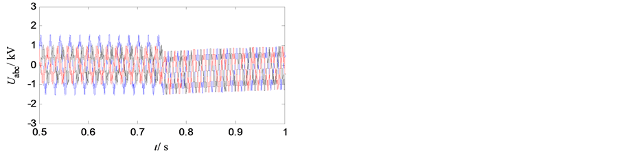 (b)
(b)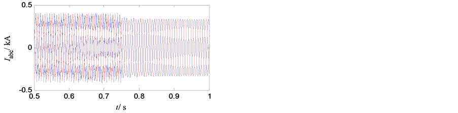 (c)
(c)
Figure 4. The simulation of system. (a) The voltage of upper and under capacitance; (b) The output voltage waveforms of STATCOM; (c) The output current waveforms of STATCOM.
thod, can effectively maintain the balance of the DC side capacitor voltage and the output current of the second harmonic suppression, thus the method for the safe and stable operation of the STATCOM has an important practical significance.
Cite this paper
Zheng, Z.Q. (2016) Research of Magnetic Bias Control System Based on STATCOM. World Journal of En- gineering and Technology, 4, 9-15. http://dx.doi.org/10.4236/wjet.2016.43D002
References
- 1. Ai, Q., Yang, X. and He, X. (2013) Research on Technologies for Improving Power Grid Transmission Capacity. Proceeding of the CSEE, 33, 34-40.
- 2. Huang, L.Q., Guo, J.B., Bu, G.Q., et al. (2012) Research Progress and Prospect of FACTS Coordinated Control. Power System Protection and Control, 40, 138-147.
- 3. Noroozian, M., Angquist, L., Ghandhari, M., et al. (1997) Improving Power System Dynamics by Series-connected Facts Devices. IEEE Transactions on Power Delivery, 12, 1635- 1641. http://dx.doi.org/10.1109/61.634184
- 4. Gibbard, M.J., Vowles, D.J. and Pourbeik, P. (2000) Interactions between, and Effectiveness of Power System Stabilizers and FACTS Device Stabilizers in Multimachine Systems. IEEE Transactions on Power Systems, 152, 748-755. http://dx.doi.org/10.1109/59.867169
- 5. Wang, H.F. (2003) Interactions and Multivariable Design of STATCOM Control. International Journal of Electrical Power and Energy Systems, 25, 387-394. http://dx.doi.org/10.1016/S0142-0615(02)00038-8
- 6. He, R.W. and Cai, Z.X. (2004) A Comment on FACTS Based on Power System Stability Analysis and Control. Relay, 32, 70-75.
- 7. Kuai, D.Z., Liu, C.M. and Wan, D. (2004) Application of Data Mining Technology on Analysis of Dispatching Data Network Business Flow. Jiangsu Electrical Engineering, 23, 1-5.
- 8. Fang, R.J. (2014) Anti-Magnetic-Bias in Inverter Based on the Pulse Width Processing. Renewable Energy Resources, 32, 584-587.