Open Journal of Medical Imaging
Vol.3 No.4(2013), Article ID:40996,9 pages DOI:10.4236/ojmi.2013.34023
Removal of the Shadow of Cervical Vertebrae from Panoramic X-Ray Images with a Tomosynthesis Method
1Department of Applied Informatics, Faculty of Science and Engineering, Hosei University, Tokyo, Japan
2Department of Oral Radiology, Asahi University School of Dentistry, Gifu, Japan
Email: ogawa@hosei.ac.jp
Copyright © 2013 Koichi Ogawa et al. This is an open access article distributed under the Creative Commons Attribution License, which permits unrestricted use, distribution, and reproduction in any medium, provided the original work is properly cited.
Received November 13, 2013; revised December 11, 2013; accepted December 17, 2013
Keywords: Panoramic; Radiography; Cervical Vertebrae; Subtraction Technique
ABSTRACT
The purpose of this study is to remove the shadow of cervical vertebrae from dental panoramic x-ray images with a tomosynthesis method and improve the contrast of details in both the teeth and jaw bones. To measure the shift-amount at each angular position that was required for reconstruction of panoramic x-ray images of the dental arch, strip images of a calibration phantom were acquired. Then, a shift-amount table was prepared from these images, and the other shiftamount table, which was used to reconstruct a panoramic image of the cervical vertebrae, was prepared by inverting the curve of the shift-amount table upside down. Using these two tables, images focused on the dental arch and cervical vertebrae of a patient were made with the original strip data of the patient. The shadow of the cervical vertebrae appearing on the image focused on the dental arch was removed using the two above-mentioned images and blurring functions defined at two focusing geometries. The validity of the proposed method was evaluated with clinically acquired data of two patients. The shadow of the cervical vertebrae was successfully eliminated, and the contrast of the front teeth and detailed structures of the jaw bones was improved. The results of the experiments showed that our proposed method was significantly effective in removing the shadow of the cervical vertebrae from conventional panoramic x-ray images.
1. Introduction
In dental imaging, many imaging techniques and imaging receptors are used in intraand extra-oral dental radiology [1]. Among these imaging techniques, dental panoramic radiography [2,3] is a technique which images teeth and jaw bones aligned on a predefined curved plane. Two types of detector are used for this imaging: one is a scintillator with a charge coupled device (CCD) detector and the other is a semiconductor detector such as cadmium telluride (CdTe) [4]. The sensitivity of the former detector is basically low, requiring a time delay integration to improve the signal to noise ratio [5]. Moreover, the response speed of the CCD detector is too slow to acquire many images of the teeth and jaw bones with slightly different angles to the dental arch. This restricts the application of a tomosynthesis method [6] that is represented by the “shift-and-add” operations to many images acquired with slightly different angles. On the other hand, because the sensitivity and response speed of the latter detector are higher than those of the former one, we can obtain many strip images of an object acquired with slightly different angles. This enables us to reconstruct an image of the teeth and jaw bones focused at a given depth with a tomosynthesis method [7,8]. Once we acquire data of a patient, we can freely reconstruct a desired layer of a given depth, and so application of the tomosynthesis technique is gradually expanding in the field of panoramic imaging. In the tomosynthesis technique, a shift-amount at each angular position defined by the location of an x-ray source and detector is required in the process of the shift-and-add operation. This shiftamount controls the position of a focused plane in the dental arch, and so if we use a large shift-amount in the process of focusing, we can also reconstruct cervical vertebrae with the strip images originally acquired. Conventional panoramic radiography is intended to focus on the teeth and jaw bones, as a result of which a blurred shadow of the cervical vertebrae overlaps on the image, thereby reducing the image contrast at the front teeth.
Suppose an image model, in which objects to be reconstructed are located only on the dental arch and curved area located symmetrical to the dental arch. We named this curve that passes through the cervical vertebrae “a cervical curve.” The location of the cervical curve is symmetrical to that of the dental arch, and so we can define the shift-amount table that is required for reconstructing the image of the cervical vertebrae. Once we make these two shift-amount tables, we can reconstruct two panoramic images, one being the conventional image of the teeth and jaw bones on which a blurred shadow of the cervical vertebrae overlaps, and the other that of the cervical vertebrae on which a blurred shadow of the teeth and jaw bones overlaps. Using above two images, the shadow of the cervical vertebrae can be removed from the conventional panoramic image with the help of image processing techniques. This paper proposed a new method to remove the shadow of the cervical vertebrae from the conventional panoramic image focused on the teeth and jaw bones. The validity of the proposed method was evaluated with the clinically obtained data of two patients.
2. Materials and Method
2.1. Method
In our proposed method, the tomosynthesis method plays a very important role. To measure the shift-amount required for a “shift-and-add” operation in the tomosynthesis method, we used a calibration phantom [8]. In the phantom, several thin wires are located at specified angular positions on the standard imaging plane of the dental arch, and the shift-amount at each position is measured as the distance needed to match the positions of a thin wire between the adjacent frame images. Using this measurement, we can obtain a table of the shift-amount at each specified angular position. The details are described in the literature [8]. Figure 1 shows an example of the shift-amount table of an actual dental panoramic apparatus. During the rotation of the x-ray source and detector around an object, several thousands strip images of the object are acquired sequentially. And thus, the
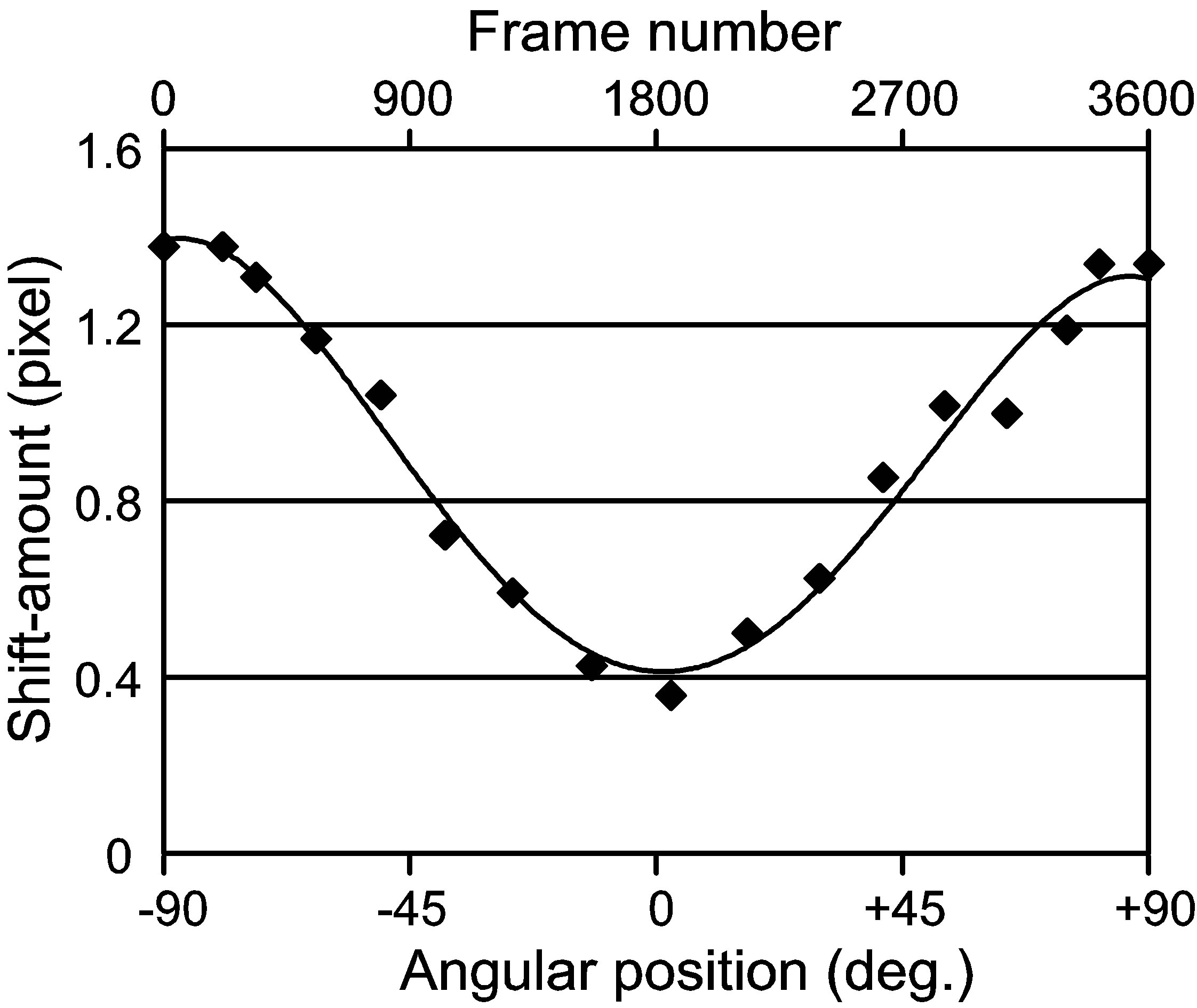
Figure 1. Shift-amount table for reconstructing an image of the dental arch.
angular position of the detector corresponds to the frame number of a series of the strip images. If the distance between the x-ray source and dental arch is always the same for any angular position, the shift-amount becomes a constant value. However, the rotation center of the x-ray source and detector moves on a specified orbit in the conventional panoramic apparatus, as a result of which the distance between the x-ray source and dental arch changes, and the shift-amount table becomes a cosine-shaped curve as shown in Figure 1.
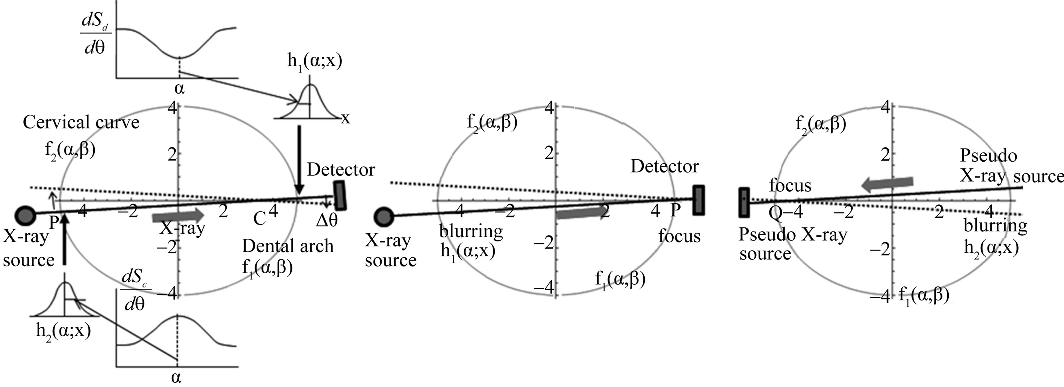
The cervical vertebrae are located on a curve that is almost symmetrical to the dental arch, and so we assumed an imaginary curve on which the cervical vertebrae are located. We named this curve “a cervical curve” as shown in Figure 2. To reconstruct the cervical vertebrae, a new shift-amount table is required. If the distance between rotation center C and point P on the dental arch is large (Figure 3(a)), the shift-amount, which corresponds to the moved distance (dSd) of point P on the dental arch for small angular movement (dq), becomes larger. If we exchange the positions of the x-ray source and detector as shown in Figure 3(c), the distance between rotation center C and point Q on the cervical curve becomes smaller, and the shift-amount, which corresponds to the moved distance (dSc) of point Q on the cervical curve for small angular movement (dq), becomes smaller. As a result, the shift amount table for the cervical curve will be nearly symmetrical (upside down) to that of the dental arch (Figures 3(b) and (d)). The theoretical background to calculate the shift-amount table is shown in the Appendix. An example of the shiftamount table for reconstructing the cervical vertebrae is shown in Figure 4.
Next, we will consider the relationship between the dental arch and cervical curve on a tomosynthesis image. For the illustration, we simplify the imaging objects, in which only two objects are located along the dental arch and cervical curve. Suppose the object distribution on the dental arch f1(α,β) and that of the cervical curve f2(α,β) as shown in Figure 5(a), where α indicates the position

Figure 2. Dental arch and an assumed cervical curve.
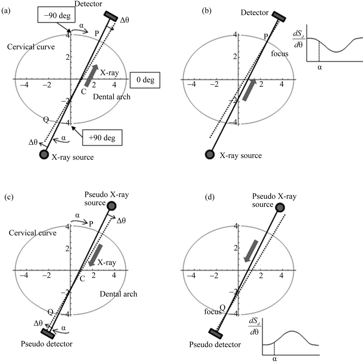
Figure 3. Geometry of the x-ray source and detector, and the shift-amount tables to make a tomosynthesis image. (a) A common geometry in the panoramic imaging, (b) A shift-amount table required to focus on the dental arch, (c) A geometry for making the tomosynthesis image of the cervical vertebrae, and (d) A shift-amount table required to focus on the cervical curve.
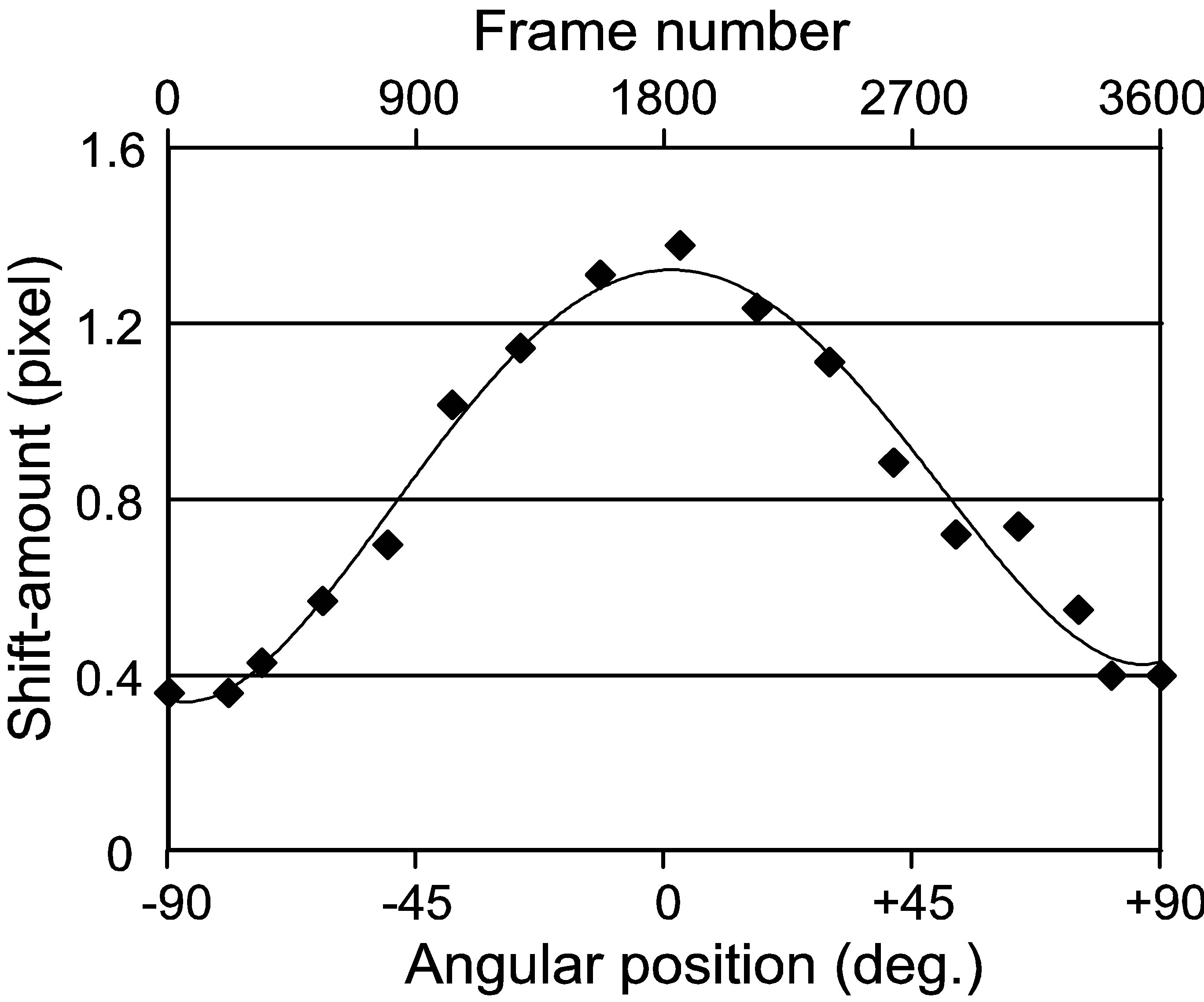
Figure 4. Shift-amount table for reconstructing an image of the cervical vertebrae.
along the dental arch or cervical curve, and β is the vertical position to the α-axis. The α- and β-axes correspond to the horizontal and vertical axes of a panoramic image, and α is the position on the curve of the dental arch for the case of the panoramic image of the tooth and jaw bones, and also α is the position on the cervical curve for the case of the panoramic image of the cervical vertebrae.
And we also assume the blurring functions h1(α;x) and h2(α;x). h1(α;x) is a blurring function at position α on the dental arch when the focal point is located on the cervical curve, and h2(α;x) is a blurring function at position α on the cervical curve when the focal point is located on the dental arch. x is a dummy variable in the α-axis. These functions are shift-variant for position α, that is, a blurring region depends on the shift-amount at position α. These functions are modeled with a Gaussian function whose full width at half maximum (FWHM) corresponds to the shift-amount at each angular position. The shape of the blurring function does not change markedly in the neighborhood of α, and so we assume that these functions are regionally shift-invariant in the small area for x = α.
A given tomosynthesis image can be represented by a
 (a) (b) (c)
Figure 5. Geometry 1 (the rotation center of the x-ray source and detector located far from the dental arch). (a) Relationship between the two shift-amount tables and blurring functions, (b) The case when a panoramic image is focused on the dental arch, and (c) The case when a panoramic image is focused on the cervical curve.
summation of two images: one is an image focused on the teeth and jaw bones or on the cervical vertebrae, and the other is that defocused using one of the above-mentioned blurring functions. That is, tomosynthesis image g1(α,β) that is focused on the dental arch is represented as follows (see Figure 5(b)):
 (1)
(1)
where ![]() means a one dimensional convolution operator for variable α. This equation means that the resultant image of the shift-and-add operation is a summation of the focused image of the teeth and jaw bones and the defocused image of the cervical vertebrae. In actual cases, a cross section of the maxillofacial region includes many organs, and we cannot represent the cross section with this simple model. However, the major attenuating objects are high density organs such as teeth and bones, and so the model can be acceptable as the first approximation.
means a one dimensional convolution operator for variable α. This equation means that the resultant image of the shift-and-add operation is a summation of the focused image of the teeth and jaw bones and the defocused image of the cervical vertebrae. In actual cases, a cross section of the maxillofacial region includes many organs, and we cannot represent the cross section with this simple model. However, the major attenuating objects are high density organs such as teeth and bones, and so the model can be acceptable as the first approximation.
In the same manner, tomosynthesis image g2(α,β) that is focused on the cervical curve is represented as follows (see Figure 5(c)):
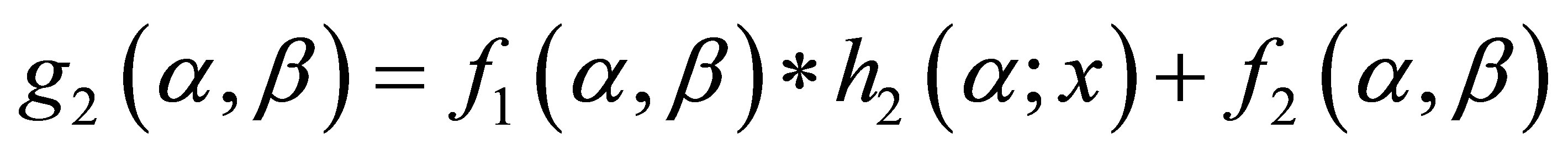 (2)
(2)
Using the above two equations, we can remove the shadow of the cervical vertebrae that overlaps on the image of the dental arch, as follows:
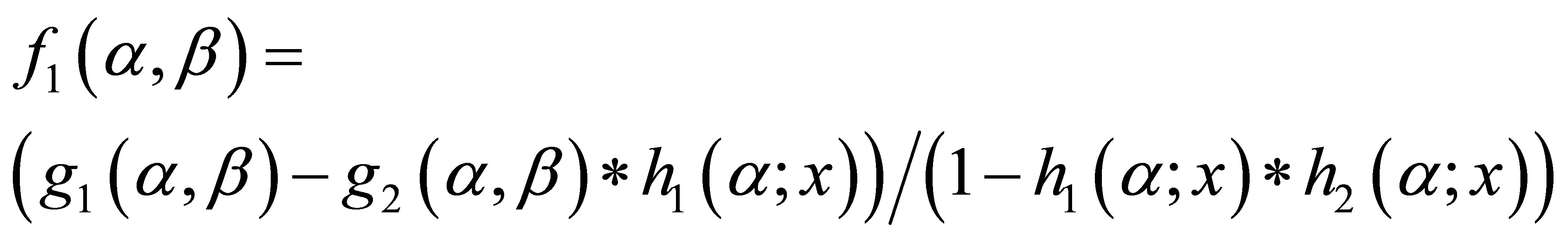 (3)
(3)
Figure 6 show the case in which rotation center C is close to the dental arch, and in this case, the shift-amount required for reconstructing the cervical curve becomes larger as shown in Figure 6(a).
2.2. Materials
In this study, we used clinical data acquired with QRMasterP (Telesystems, Co. Ltd., Osaka, Japan). The number of strip images used for reconstructing a tomosynthesis image was 3600, and the size of a strip image was 50 × 1500 pixels. The size of a pixel was 0.2 × 0.2 mm2. The x-ray tube voltage was 90 kV and tube current was 10 mA. The data acquisition time was 12 sec. Using the above conditions, we acquired data of two patients (male, ages 45 and 52). This study received the approval of the ethics committee of Asahi University, School of Dentistry.
3. Results
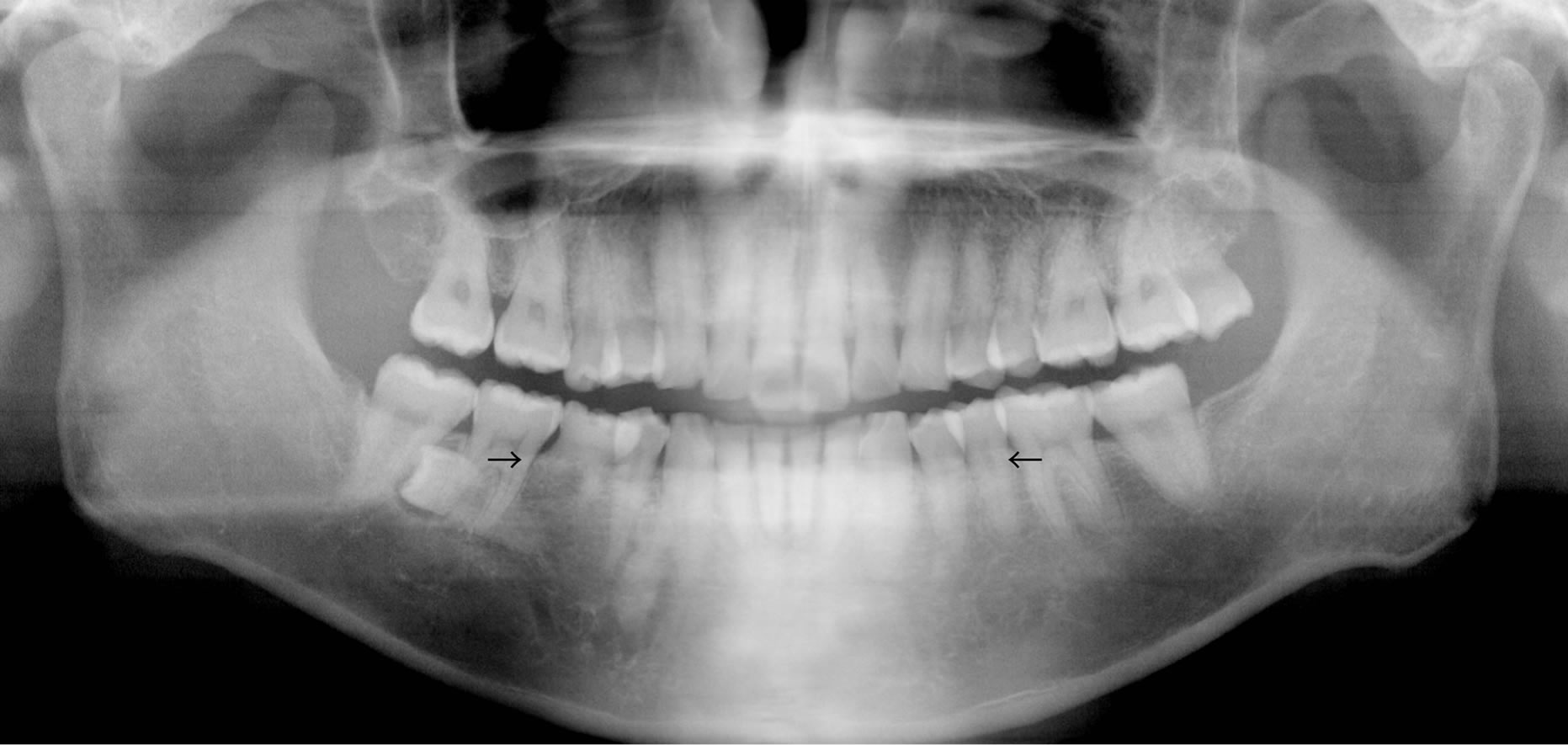
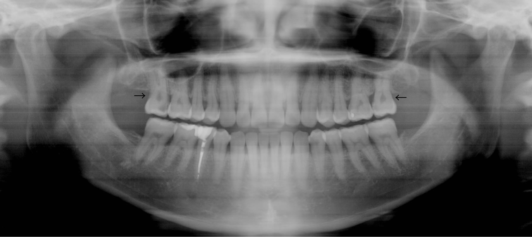
Figure 1 shows the shift-amount table measured with the calibration phantom, which is required for reconstructing a panoramic x-ray image of the dental arch. Figure 4 shows the shift-amount table that is required for reconstructing the cervical vertebrae. This table was made by inverting the shape of the shift-amount curve shown in Figure 1. Figure 7(a) shows the original tomosynthesis image [g1(α,β)] focused on the dental arch, on which the shadows of the cervical vertebrae overlaps. Figure 7(b) shows the tomosynthesis image [g2(α,β)] of the cervical vertebrae, on which the shadows of the teeth and jaw bones overlap. Figure 7(c) shows the resultant image [f1(α,β)] of the teeth and jaw bones after removing the shadow of the cervical vertebrae from the original tomosynthesis image [g1(α,β)]. This image clearly visualized the shape of the front teeth and trabeculae in the jaw bones. Figure 8 shows the density profiles of Figures 7(a) and (c). Figure 9" target="_self"> Figure 9 shows the results of the other pa-
 (a) (b) (c)
Figure 6. Geometry 2 (the rotation center of the x-ray source and detector located close to the dental arch). (a) Relationship between the two shift-amount tables and blurring functions, (b) The case when a panoramic image is focused on the dental arch, and (c) The case when a panoramic image is focused on the cervical curve.
 (a)
(a)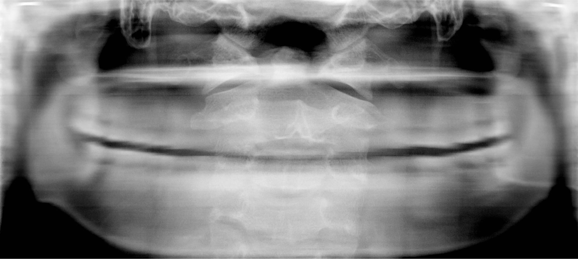 (b)
(b) (c)
(c)
Figure 7. Tomosynthesis images of patient (I): (a) Teeth and jaw bones on the dental arch are focused (conventional panoramic image), (b) Cervical vertebrae on the cervical curve are focused, and (c) The shadow of the cervical vertebrae is removed from the original panoramic image.

Figure 8. Density profiles of tomosynthesis images (upper: Figure 7(a), lower: Figure 7(c)) along a line indicated in Figure 7(a).
tient: (a) is the original panoramic image, (b) is the tomosynthesis image of the cervical vertebrae, and (c) is the processed image. Figure 10 shows the density profiles of Figure 9" target="_self"> Figure 9(a) and (c). The results showed that our proposed method can remove the shadow of the cervical vertebrae effectively.
4. Discussion
Dental panoramic radiography is very useful to diagnose diseases of the teeth. The concept of tomosynthesis enables us to reconstruct an image focused on any layer in the dental arch. One of the key technologies of this me-
 (a)
(a)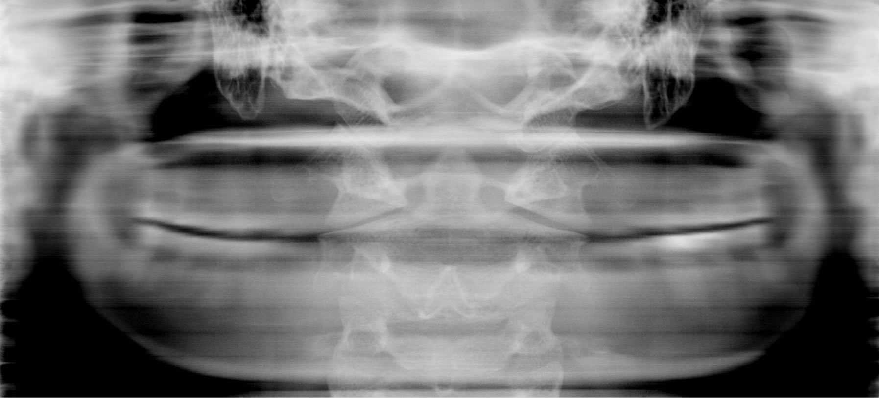 (b)
(b)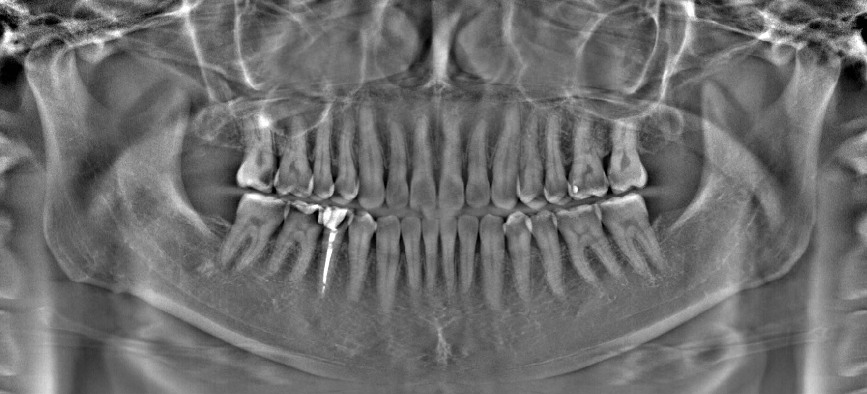 (c)
(c)
Figure 9. Tomosynthesis images of patient (II): (a) Teeth and jaw bones on the dental arch are focused (conventional panoramic image), (b) Cervical vertebrae on the cervical curve are focused, and (c) The shadow of the cervical vertebrae is removed from the original panoramic image.

Figure 10. Density profiles of tomosynthesis images (upper: Figure 9(a), lower: Figure 9(c)) along a line indicated in Figure 9(a).
thod is the development of the CdTe semiconductor detector that acquires photons with very small pixels less than 0.2 × 0.2 mm2 with a very high speed (300 frames/sec). There are two types of detectors: one is the energy integration detector [7] and the other is the photon counting detector [9]. Both detectors measure photons with a high signal to noise ratio, and so these detectors are less affected by a dark current compared to that of the flat panel detector consisting of a CsI(Tl) scintillator and CCD [4]. The other key technology is the method to measure the shift-amount required for reconstructing an object with variable focusing schemes. The shift-amount table differs from each panoramic apparatus making measurement of the shift-amount table of each apparatus using the standard calibration phantom necessary to focus an image at a given layer accurately. And if we use the shift-amount table, we can focus not only on any curved plane parallel to the standard dental arch, but also on any tilted plane by changing the contents of the table [8]. This enables us to diagnose various dental diseases easily. And so we have been studying the application of dental panoramic imaging with the tomosynthesis method [10].
One of the advantages of the panoramic apparatus compared to the dental CT apparatus is its low radiation dose. The dose required for the panoramic imaging is 1/7 ~ 1/20 of the conventional CT imaging including multislice CT [11]. However, the panoramic imaging is a modification of conventional x-ray imaging, and so unnecessary anatomical structures overlap on the tomosynthesis image, even though we focus the image on a specified plane such as the dental arch. This is one of the disadvantages compared to CT imaging. That is, the shadow of the cervical vertebrae overlaps on the tomosynthesis image focused on the teeth and jaw bones reducing the contrast of the image.
To overcome this shortcoming, we developed a new method able to remove the shadow of the cervical vertebrae. In our proposed method, the structure of the organs in the maxillofacial regions was simplified, and they were assumed to be located on the dental arch and cervical curve, which were symmetrical. The shadow was removed with two reconstructed images, which were focused on the dental arch and cervical curve, and the blurring functions defined at both curves. The results showed that the proposed method could remove the shadow of the cervical vertebrae effectively. These panoramic images of the patients’ data showed a different appearance of the teeth and jaw bones in each case, but our proposed method could accurately remove the shadow of the cervical vertebrae. In these processed images, the contrast of the front teeth and trabeculae of the jaw bones was improved as shown in Figures 7(c) and 9(c). The removal of the cervical vertebrae was clearly confirmed with the resultant images and density profiles (Figures 8 and 10). This technology is expected to improve the accuracy of diagnosis with dental panoramic images.
In this paper, the location of the cervical curve was assumed to be symmetrical to the dental arch. Occasionally, the cervical vertebrae may not be located on the curve. In this case, removal of the shadow may be less complete as compared to the case in which the cervical vertebrae are on the curve. On the other hand, the contrast of the front teeth or jaw bones is improved compared to the original panoramic x-ray image. Moreover, the cervical vertebrae are not curvaceous materials, but volumetric materials, and so the degree of removal of the shadow depends on the size and shape of the cervical vertebrae. But even in this case, the contrast of the front teeth or jaw bones is improved compared to the original panoramic x-ray image. In this paper we did not describe details in the validity on clinical studies, but the elimination of the shadows of cervical vertebrae was obvious, and so we will study the application of this method to the diagnosis such as dental caries, periodontitis, and maxillary sinusitis in the future.
In conclusion, we proposed a removal method of the shadow of the cervical vertebrae from conventional panoramic x-ray images with the tomosynthesis method. The results of the experiments with the clinically obtained data showed that the cervical vertebrae were removed to a large extent in the resultant images.
REFERENCES
- B. Vandenberghe, R. Jacobs and H. Bosmans, “Modern Dental Imaging: A Review of the Current Technology and Clinical Applications in Dental Practice,” European Radiology, Vol. 20, No. 11, 2010, pp. 2637-2655. http://dx.doi.org/10.1007/s00330-010-1836-1
- O. E. Langland, R. P. Langlais, M. D. McDavid and A. M. DelBalso, “Panoramic Radiology,” 2nd Edition, Lea & Febiger, Philadelphia, 1989.
- A. G. Farman and T. T. Farman, “Extraoral and Panoramic Systems,” Dental Clinic in North America, Vol. 44, 2000, pp. 257-272.
- M. Noujeim, T. Prihoda, W. D. McDavid, K. Ogawa, K. Seki, T. Okano, et al., “Pre-Clinical Evaluation of a New Dental Panoramic Radiographic System Based on Tomosynthesis Method,” Dentomaxillofacial Radiology, Vol. 40, No. 1, 2011, pp. 42-46. http://dx.doi.org/10.1259/dmfr/73312141
- J. Lu, Y. Liu, R. Liu and R. Yu, “The Application of TDICCD in Dental Panoramic X-Ray Radiography,” Proceedings of IEEE International Conference on Computer Science and Automation Engineering, Vol. 2, 2012, pp. 800-803.
- D. G. Grant, “Tomosynthesis: A Three-Dimensional Radiographic Imaging Technique,” IEEE Transaction on Biomedical Engineering, Vol. 19, No. 1, 1972, pp. 20-28. http://dx.doi.org/10.1109/TBME.1972.324154
- Internet Publication. http://www.ajat.fi/index.php
- K. Ogawa, R. P. Langlais, M. D. McDavid, M. Noujeim, K. Seki, T. Okano, et al., “Development of a New Dental Panoramic Radiographic System Based on a Tomosynthesis Method,” Dentomaxillofacial Radiology, Vol. 39, No. 1, 2010, pp. 47-53.
- K. Ogawa, T. Kobayashi, F. Kaibuki, T. Yamakawa, T. Nagano, D. Hashimoto, et al., “Development of an Energy-Binned Photon-Counting Detector for X-Ray and Gamma-Ray Imaging,” Nuclear Instrument Method in Physics Research A, Vol. 664, No. 1, 2012, pp. 29-37. http://dx.doi.org/10.1016/j.nima.2011.10.009
- A. Katsumata, K. Ogawa, K. Inukai, M. Matsuoka, T. Nagano, H. Nagaoka, et al., “Initial Evaluation of Linear and Spatially Oriented Planar Images from a New Dental Panoramic System Based on Tomosynthesis,” Oral Surgery, Oral Medicine, Oral Pathology, Oral Radiology, and Endodontology, Vol. 112, No. 3, 2011, pp. 375-382.
- O. S. Sezgin, S. Kayipmaz, D. Yasar, A. B. Yilmaz and M. H. Ozturk, “Comparative Dosimetry of Dental Cone Beam Computed Tomography, Panoramic Radiography, and Multislice Computed Tomography,” Oral Radiology, Vol. 28, No. 1, 2012, pp. 32-37. http://dx.doi.org/10.1007/s11282-011-0078-5
Appendix
The shift-amount table that is required for reconstruction of the cervical vertebrae can be obtained with the following method. For the mathematical description, we model the dental arch with an ellipsoid with long axis a1 and short axis b1. The center of rotation C(xc,yc) of the x-ray source and detector moves while the data acquisition as shown in Figure A1 (broken line). The solid line consists of the x-ray source and detector sweeps the dental arch while C moves along a predefined orbit. Here we define the orbit of the rotation center as a quadrant, and assume that the center moves from Cs to Ce on the orbit. In this model, data are measured for half of the dental arch (upper right region in Figure A1) for the sake of simplicity. The shift-amount at a given point P(x1,y1) on the dental arch can be calculated from the difference of the projected positions of point P onto the detector plane with small angle of q. The shift-amount between the neighboring frame images becomes D1sin q on the dental arch, where D1 is the distance between points C and P as follows:
 . (4)
. (4)
Point P is on the ellipsoid denoted by the following equation for x1 > 0:
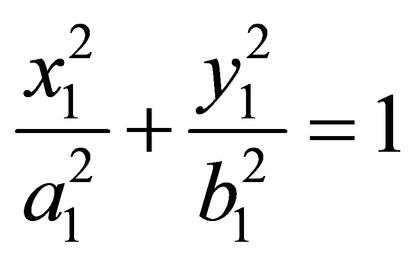 . (5)
. (5)
So we can calculate the distance D1 for given position P. Next, we define distance Rs between the rotation center and x-ray source, and distance Rd between the rotation center and detector, and so we can obtain the shiftamount Sd for the small angle of q at the detector position:

Figure A1. Simulation geometry.
 (6)
(6)
where D1cos q is the length after the x-ray source and detector rotate by small angle of q [8]. For very small angle q, Equation (6) becomes
 . (7)
. (7)
Thus, the shift amount becomes as follows:
 . (8)
. (8)
Next we assume a cervical curve defined by an ellipsoid with long axis a2 and short axis b2. For given point Q(x2,y2) on the cervical curve, Q is opposite to P for the rotation center C. When we exchange the locations of the x-ray source and detector, the shift-amount becomes D2sinq where D2 is the distance between points C and Q. That is
 . (9)
. (9)
Point Q is on the ellipsoid, and so we can obtain the next equation for x2<0:
 . (10)
Distance D2 can be calculated with Equation (9) at given point Q, and the shift-amount Sc for small angle of q at the detector position becomes as follows:
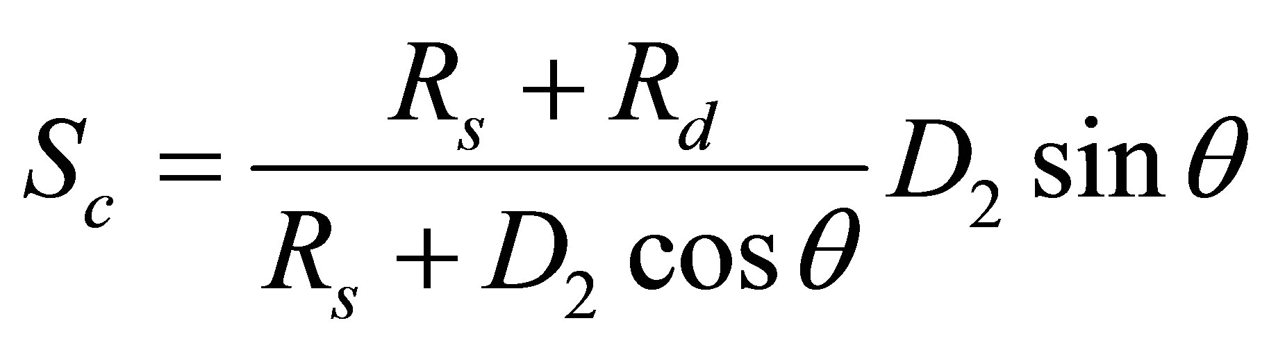 . (11)
For very small q, Equation (11) becomes as follows:
 . (12)
Thus, the shift amount becomes as follows:
 . (13)
To calculate an example of the shift-amount tables (the dental arch and cervical curve), we set the following parameters, a1 = 5, b1 = 3, a2 = 5, b2 = 3, Rs = 42, and Rd = 12 (cm). The radius of rotation of the rotation center is 2 cm, and C moves from Cs (0,−2) to Ce (2,0). We assumed that the x-ray source and detector sweep the upper half of the dental arch in Figure A1. Figure A2 shows the shift amount tables that are used to focus on the dental arch and cervical curve (angular range: −90 - 0 deg). These curves somewhat differ from the actual curves as shown in Figures 1 and 5. The reason is as follows. We modeled the dental arch as an ellipsoid and the orbit of the

Figure A2. Shift-amount tables theoretically calculated with the simulation geometry.
rotation center a quadrature. And in this simulation we assumed that the rotation center moves with a uniform angular velocity in the angular range ((Cs) p/2 - (Ce) 0 radian). And the frame rate was 200 (frames/deg). The shift-amount table depends on the shape of the cervical curve as well as that of the dental arch, and the predefined parameters of the panoramic apparatus used to acquire original data.