Journal of Electromagnetic Analysis and Applications
Vol. 2 No. 2 (2010) , Article ID: 1391 , 6 pages DOI:10.4236/jemaa.2010.22014
Compact Narrow Band Non-Degenerate Dual-Mode Microstrip Filter with Etched Square Lattices
![]()
Department of Electronics, Madhav Institute of Technology and Science, Gwalior, India.
Email: pks_65@yahoo.com
Received September 11th, 2009; revised October 13th, 2009; accepted October 17th, 2009.
Keywords: Microstrip, Dual mode, Narrowband filter, Square patch resonator
ABSTRACT
A compact narrowband non-degenerate dual-mode microstrip filter with square shape cuts is presented. The structure is developed by loading the conventional non-degenerate dual-mode resonator by open circuit stubs at two opposite corners. The filter bandwidth is controlled by only decreasing the higher cutoff frequency of the conventional type. With Square shape cuts, return loss is improved. A 20% fractional bandwidth filter is designed and implemented on FR4 material with 4.4 dielectric constant and 1.6 mm thickness at center frequency of 1.5 GHz with passband of 1.3 GHz to 1.6 GHz. Analysis has been achieved using the IE3D simulator. Experimental results do agree with simulations.
1. Introduction
Now-a-days compact microwave filters are widely used in various wireless communication applications. Dualmode resonators have been used for such purposes. Each of dual-mode resonators act as a doubly tuned resonant circuit and therefore the number of resonators required for a given filter is reduced by half, resulting in a compact configuration. Dual-mode microstrip resonators have the advantages of low profile, simple fabrication, ease of integration in addition to low cost. The first microstrip dual-mode filter was presented by Wolff [1] in 1972. Degenerate modes based filters have been investigated in various topologies such as square patch [2], circular patch, triangular patch, square loop [3], circular ring [4] and meander shape [5]. Square and circular patches structures have negligible conductor loss but suffer from higher radiation loss. However, square loop and circular ring structures have less radiation loss but suffer from higher conductor loss, especially for thin strip conductors [2]. Degenerate dual mode filters have usually narrow bandwidth of (< %5). Filters with higher bandwidth up to 25% have been investigated using non-degenerate dual-mode structure [6–7].
2. Proposed Structure and Modes of Operation
The fields within a square patch resonator can be expanded by the TMzmn0 modes [2], where ‘z’ is perpendicular to the ground plane. The two fundamental degenerate modes correspond to TMz100 and TMz010 and the first higher order mode correspond to TMz110 [6]. These three modes can be excited simultaneously by a square shape resonator with feed lines, as shown in Figure 1. The simulated response is shown in Figure 2.
The etching of slots in square patch resonator as shown in Figure 3 decreases the resonance frequencies of the

Figure 1. Layout of square patch resonator with feed lines (All dimensions are in mm)

Figure 2. Simulated response of square patch resonator with feed lines

Figure 3. Layout of square patch resonator after etching slots (All dimensions are in mm)
three modes but the resonance frequency of the mode TMz110 decreases faster. Therefore, band pass filter behavior can be obtained [7]. This is shown in Figure 4. The resultant size and bandwidth decreases as the slot length increases. The square patch has a length W, while the slots have equal lengths L and width S. The physical dimensions of the simulated patch are W = 45.6 mm, L = 9 mm and S = 3 mm. Denoting f1 as the resonance frequency of the degenerate modes TMz100 and TMz010 and f2 as the resonance frequency of the mode TMz110. The effect of the slots length L on the resonance frequencies f1 and f2 for the patch is that the two resonance frequencies, f1 and f2, decrease as L increases [7]. The difference f2 - f1 can be used as first approximation of the possible bandwidth of the filter. For L = 9 mm, a fractional bandwidth of about 33% can be obtained using the given parameters.
Based on this design configuration, it is difficult to achieve bandwidth less than this value. However, loading the patch by open circuit stubs as shown in Figure 5 will decrease the resonance frequency f2 of the mode TMz110 and approximately maintains the resonance frequency of the degenerate modes constant. Therefore, band pass filters with fractional bandwidth less than 25% can be achieved.
The layout of the filter with the stubs of width 1 mm and length 12 mm can be seen in Figure 5. The subsequent effect on the resonance frequencies f1 and f2 is

Figure 4. Simulated response of square patch resonator after etching slots

Figure 5. Layout of non-degenerate dual-mode filter with stubs of length 12 mm
shown in Figure 6. This analysis is carried out using the moments method IE3D simulator, on a conducting patch of W = 45.6 mm on a substrate of dielectric constant 4.4, with height 1.6 mm. The slot length and width used are 9 mm and 3 mm, respectively. These parameters have been chosen to fix f1 at 1.3 GHz.
As described in the previous section, almost no effect is observed on the resonance frequency of the first two degenerate modes TMz100 and TMz010. The resonance frequency of these modes f1 is almost constant and equal to 1.3 GHz for stubs length of 0 to 18 mm. However, the first higher order mode TMz110 is highly affected and its resonance frequency f2 decreases. This variation allows the design of narrow band filter, with careful control of its bandwidth. Bandwidth selection can be obtained by first choosing f1 and then finding the appropriate stub lengths for a specific value of f2.
3. Filter Design Parameters
For the proposed narrowband band pass filter the design parameters are:
Dielectric Constant = 4.4Height of Substrate = 1.6 mmCorresponding length of the Square patch, W = 45.6 mmCorresponding width of the slots, S = 3mmCorresponding length of the slots, L = 9mmCorresponding width of the stubs, Ws = 1mmCorresponding length of the stubs, Ls = 16mmThe layout of the non-degenerate dual-mode filter with stubs of length 16 mm is shown in Figure 7 and Figure 8 shows the fractional bandwidth obtained is about 20% in

Figure 6. Simulated response of non-degenerate dual-mode filter with stubs of length 12 mm

Figure 7. Layout of the dual-mode filter with stubs of length 16 mm
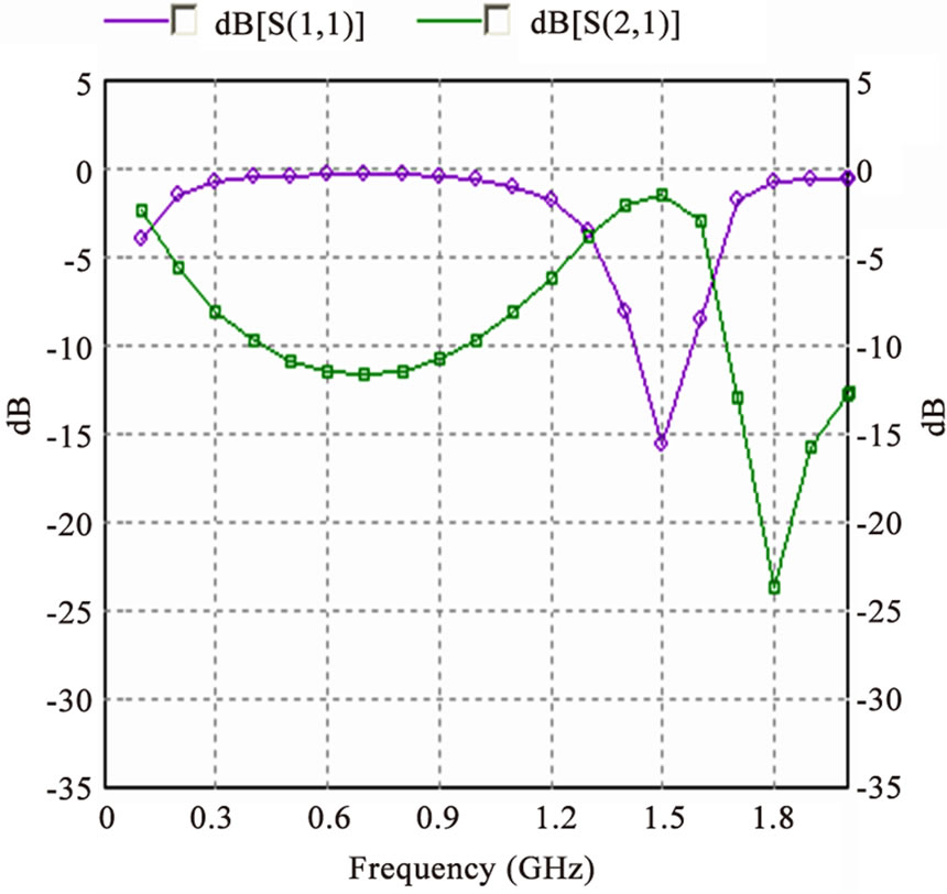
Figure 8. Simulated response of dual-mode filter with stubs of length 16mm
the passband 1.3 GHz -1.6 GHz and the return loss is found to be 15.11dB. The layout as shown in Figure 9, is obtained after etching one square lattice of dimension of 6 mm × 6 mm, on the center of the conventional nondegenerate dual mode filter. The corresponding return loss of the bandpass filter at the center frequency is found to be improved and becomes 22.56 dB. The fabricated layout is shown in Figure 10. The simulated and measured results are shown in Figures 11, 12.

Figure 9. Layout of the non-degenerate dual mode filter with etching of one square lattice

Figure 10. Photographed layout of non-degenerate dual mode filter with etching of one square lattice

Figure 11. Simulated and measured results of insertion loss of non-degenerate dual mode filter with etching of one square lattice

Figure 12. Simulated and measured results of return loss of non-degenerate dual mode filter with etching of one square lattice

Figure 13. Layout of the non-degenerate dual mode filter with eight square lattices

Figure 14. Photographed layout of the non-degenerate dual mode filter with eight square lattices
Now, with additional eight small square lattices of dimension 2mm × 2mm etched as shown in Figure 13, the frequency response can further be improved as shown in Figures 14, 15. The return loss now is 26.12 dB. Figure 16 shows the fabricated layout of the non-degenerate dual mode filter with eight square lattices.
Figure 17 shows the layout of non-degenerate dual mode filter with a carpet of square lattices of very small dimension 1mm × 1mm. It further improves the return loss to 30.06 dB which is shown in Figure 18.

Figure 15. Simulated and measured insertion loss plots for non-degenerate dual mode filter with eight small square lattices

Figure 16. Simulated and measured return loss plots for non-degenerate dual mode filter with eight small square lattices

Figure 17. Layout of non-degenerate dual mode filter with carpet square lattices

Figure 18. Simulated response of non-degenerate dual mode filter with carpet square lattice
4. Conclusions
A compact narrow band filter based on non-degenerate dual-mode resonator is proposed. The narrow bandwidth characteristic is achieved by loading the slotted square patch at opposite corners. Such loading affect only the higher cutoff frequency of the filter. The effect of this loading has been discussed.
For improved performance in terms of return loss for the narrowband band pass filter, square shape lattices of different dimensions etched on the conventional design. It significantly improves the return loss with 30.06 dB at the center frequency. Hence, a narrowband filter of fractional bandwidth 20% is designed and implemented with better performance on transmission and reception. Good agreement between simulated and measured responses is observed.
5. Acknowledgment
The authors thankfully acknowledge the financial support provided by All India Council of Technical Education, New Delhi, India.
REFERENCES
- I. Wolff, “Microsrtip bandpass filter using degenerate modes of microstrip ring resonator,” Electron Letter, Vol.8, No. 12, pp. 302–303, 1972.
- J. S. Hong and M. J. Lancaster, “Microstrip filters for RF/Microwave applications,” John Wiley & Sons, Inc., New York, 2001.
- J. S. Hong and M. J. Lancaster, “Bandpass characteristics of new dual-mode microstrip square loop resonators,” Electronic Letter, Vol. 31, pp. 891–892, 1995.
- J. C. Liu, C. S. Cheng, and L. Yao, “Dual-mode double-ring resonator for microstrip band-pass filter design,” Microwave Optical Technology Letter, Vol. 36, pp. 310–314, 2003.
- J. S. Hong and M. J. Lancaster, “Microstrip bandpass filter using degenerate modes of a novel meander loop resonator,” IEEE Microwave Quided Wave Letter, Vol. 5, No. 11, pp. 371–372, 1995.
- A. F. Sheta, N. Dib, and A. Mohra, “Investigation of new non degenerate dual-mode microstrip patch filter,” IEEE Proceedings-Microwave Antennas Propagation, Vol. 153, No. 1, pp. 89–95, 2006.
- A. F. Sheta, “Narrow band compact non-degenerate dual-mode microstrip filter,” 25th National radio science conference (NRSC’08), Faculty of Engineering, Tanta University, 2008.
- G. Mattaei, L. Young, and E. M. T. Jones, “Microwave filters, impedance matching networks, and coupling structures,” Artech House, Norwood, MA, 1980.