Engineering
Vol.08 No.12(2016), Article ID:72924,10 pages
10.4236/eng.2016.812078
Evaluating Oblique Shock Waves Characteristics on a Double-Wedge Airfoil
Jorge Luis Garrido Tellez1, Eusebio Hernandez-Martinez1, Miguel Toledo Velazquez2, Jose Angel Ortega Herrera2, Pedro Quinto-Diez2
1Instituto Politecnico Nacional SEPI ESIME Ticoman, Ciudad de Mexico, Mexico
2Instituto Politecnico Nacional SEPI ESIME Zacatenco, Ciudad de Mexico, Mexico

Copyright © 2016 by authors and Scientific Research Publishing Inc.
This work is licensed under the Creative Commons Attribution International License (CC BY 4.0).
http://creativecommons.org/licenses/by/4.0/


Received: September 6, 2016; Accepted: December 19, 2016; Published: December 22, 2016
ABSTRACT
Numerical and experimental study to evaluate aerodynamic characteristics in supersonic ow over a double wedge airfoil is carried out using Fluent software and a supersonic wind tunnel, respectively. The Schlieren visualization method was also used to develop the experimental step of this study. The supersonic wind tunnel reached a proximately a Mach number of 1.8. The result got showed oblique shock waves visualization on double-wedge airfoil and the numerical simulation, the flow behavior as function of Mach number, pressure, temperature and density in the flow field on the computational model. The simulation allowed to observe the shock wave and the expansion fan in the leading and tailing edge of double-wedge airfoil. From the numerical and experimental comparison, an agreement at the shock wave angle and Mach number was observed, with a difference about 1.17% from the experimental results.
Keywords:
Oblique Shock Waves, Supersonic Airfoil, Flow Visualization, Numerical Simulation, Schlieren Method

1. Introduction
It is very relevant to understand the compressible fluid ow and some phenomenon presented in compressible ow turbomachines, blades cascades, aeronautics, aerodynamics and in any fluid motion where exist high ow velocities. Traditionally, supersonic airfoils are classified into two types, namely double wedge and bi-convex airfoils. In internal and external flows at high velocities, normal and oblique shock waves formation are presented. The shock waves generate irreversibilities and discontinuities in the flow, vibration and aeroacoustics noise [1] . These singularities increase the drag which is undesirable in the supersonic flow field. Although the shock waves thickness is about 2 µm, there are accelerations and sudden changes in fluid properties like velocity, pressure, temperature and density. If the flying object is a long with sharp wedge front, a steady oblique shock wave will be generated. The oblique shock wave produced by a three dimensional wing has been analyzed in [2] [3] [4] . The linear stability of oblique shock waves has been studied in [5] , the author studied the stability with respect to small perturbation in the incoming ow and in the solid surface. Recently, double wedge airfoils are designed to have a better lift to drag ratio when compared to subsonic profiles in supersonic flight [6] . In fact, this type of wing profiles performs quite excellent in the supersonic flight regime but would lead to disastrous performance at low speed due to those singularities [7] . In Ref. [8] a study on the aerodynamic response of double wedge airfoil in supersonic ow with free stream Mach number is presented, they varied the angle of attack and thickness to chord ratio and performed numerical simulation using adaptive grids on a Comsol Multi-physics model. In Ref. [9] an analysis of the incompressible Navier-Stokes and elastodynamics equations in the Lagrangian- Eulerian framework is presented. They developed a numerical simulation of the fluid structure interaction effect on a double wedge airfoil. In most studies, researchers have combined analytical-experimental and numerical methods to address this class of problems, see for example [10] . This paper presents a numerical simulation and experimental study about oblique shockwave on symmetrical double-wedge airfoil by mean of Mach number, pressure, temperature and density behavior. The numerical simulation and experimentation were made using the fluent software and a supersonic tunnel, respectively. Frequently, it is time consuming and expensive to test supersonic airfoils for extracting supercritical ow characteristics. The main purpose of this study is to evaluate oblique shock waves characteristics on a double-wedge airfoil by comparing their numerical behaviors and simulation effects with corresponding experimental testing. Section 2 presents the experimental development that includes the procedure of oblique shock wave visualization on the double-wedge airfoil by means of the Schlieren method. In Section 3, the aim is focused on the simulation model, by describing the computational model and boundary conditions implemented in the commercial software. Section 4 presents the results; numerical results are compared with the experimental data to show the validity of the computational model. Finally, Section 5 outlines some concluding remarks of this comparison.
2. Experimental Development
Experimentation was carried out in a supersonic wind tunnel. The test section has a rectangular shape, the top wall has the convergent-divergent profile and the bottom wall plate has 25 pressure taps, see Figure 1.
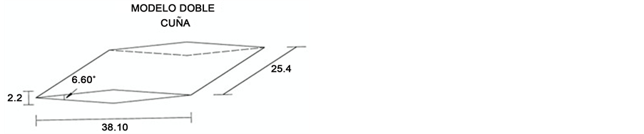
The double-wedge airfoil dimensions are 38.10 by 25.40 mm with the angle of 6.60. The double-wedge airfoil is showed in Figure 2.
In Figure 1, circle containing double wedge airfoil represents the Schlieren window.
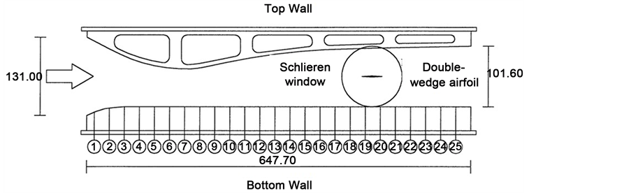
Figure 1. Test section, with 25 pressure taps, dimensions (mm).
 (a) (b)
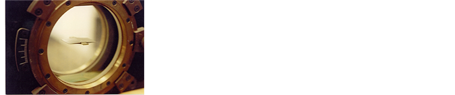
Figure 2.The double-wedge airfoil: (a) experimental setup; (b) dimensions (mm).
On the other hand, with the aim to know the flow behavior in the double-wedge airfoil, an experiment was realized at 1.6 Mach number and the static pressure data were registered at this condition. The static pressure used to compute the Mach number, temperature and density in the wind tunnel test section. These results are showed in Table 1, for a stagnation pressure of 79,593 Pa. The oblique shock wave visualization on the double-wedge airfoil by means of the Schlieren method was carried out at the conditions showed in the Table 1. Figure 3 shows the flow visualization and the oblique shock angle on the double-wedge airfoil.
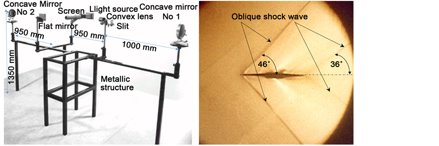
The Schlieren method consists in emitting a ray of light from the light source of 12 volts, this ray passes through a convex mirror and then by a slit, that strikes the concave mirror No. 1. After that this light ray passes through the Schlieren window of the supersonic wind tunnel, where is located the double wedge profile and it is reflected into the concave mirror No. 2. Therefore the light ray is projected on a plane mirror, which is located in front of the screen where resulting image is projected, Figure 3(b). This phenomenon is a technique for projecting optical images due to the air refractive index. Schlieren systems are used to visualize the flow away from the surface of an object.
3. Numerical Simulation
Calculations have been performed with a commercial software FLUENT. This code uses the finite volume method and Navier-Stokes equations are solved on a structured grid. The code solves the fully compressible Navier-Stokes equations with implicit formulation. Turbulence is simulated with the standard-Є (two equations) model, type
 (a) (b)
Figure 3. Schlieren method and the oblique shock wave on the double-wedge airfoil at leading and tailing: (a) flow visualization; (b) oblique shock angles.

Table 1. Conditions of the test, in the supersonic wind tunnel.
1aPatm597 mm de Hg, Temperature 21˚C; bMay 30 2016, 11:00 Time.
density based, steady, 2D space planar, velocity formulation absolute and the special discretization is, gradient: Green-Gauss, cel. Based, flow: Second Order Upwind, modified turbulent viscosity: First Order Upwind. Preliminary results of the study have reported in [11] , in which the Spalart-Almaras turbulence model and a largest volume control for geometry were used.
3.1. The Standard k-Є Model
The standard k- model is a semi-empirical model based on transport model equations for the turbulent kinetic energy (k) and its dissipation rate (
 ). The transport model equation for k is derived from the exact equation, while the transport model equation for
  is obtained by using physical reasoning and bears little resemblance to its mathematically exact counterpart. In the derivation of the k-
 model, it was assumed that the flow is fully turbulent.
3.2. Transport Equations for the Standard k-Є Model
The turbulent kinetic energy and its rate of dissipation are obtained from the following transport equations:
 (1)
(1)
 (2)
(2)
 (3)
(3)
In these Equations (1)-(3), GK represents the generation of turbulent kinetic energy due to buoyancy, YM represents the contributions of the fluctuating dilation in compressible turbulence to the overall dissipation rate,  ,
,  , and
, and , are constants, σk and
  are the turbulent Prandtl numbers for k and ϵ respectively.
3.3. Model Constants
The model constants, energy Prandtl is 0.85, wall Prandtl number is 0.85,  ,
,  ,
,  , σk and
  are the empiric constants having the following default values:
 (4)
(4)
The degree to which  is affected by the buoyancy is determined by the constant
 , it is not specified, but it is instead calculated according to the following relation.
 (5)
(5)
where , the component of the flow velocity is parallel to the gravitational vector and
  is the component of the flow velocity perpendicular to the gravitational vector. In this way,
  will become 1 for buoyant shear layer for which the main flow direction is aligned with the direction of gravity. For buoyant shear layers that are perpendicular to the gravitational vector,
  will be zero.
3.4. Computational Model and Boundary Conditions
Figure 4 shows the computational model and Table 2 shows the boundary conditions. In particular, it describes the type grid, mesh and fluid properties that are used in the computational model.
4. Analysis and Results Comparison
Figure 5 shows the oblique shock waves in the leading edge and trailing edge double wedge airfoil at 1.6 Mach number. Also shows the compression zone, the ach number decreases to 1.4 due at change of flow direction, while expansion zone the flow is accelerating to reach a 1.6 Mach number. The Mach angle in oblique shock wave in the leading edge and trailing edge are 47˚ and 37˚, respectively.
With the aim to visualize the flow, the Schlieren method was used. Figure 3 shows the implementation, and the oblique shock angles, 46˚ and 36˚, for the oblique shock waves. The behavior of static pressure field on the double-wedge airfoil can be seen in Figure 6.
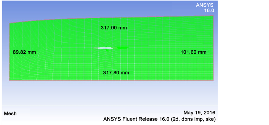
Figure 4. The computational model.
Table 2. Boundary conditions, type grid and fluid properties.

Figure 5. The oblique shock waves in the leading edge and trailing edge double-wedge airfoil at 1.6 Mach number.

Figure 6. Static pressure field on the double-wedge airfoil.
Static temperature behavior is showed in Figure 7, at 1.6 Mach number the temperature is 192 K. The static temperature before the oblique shock wave at the leading edge is 200 K, after that shock cross the shock wave, it changes its direction entering in a compression zone where its velocity is reduced and its temperature increases. Subse-

Figure 7. Static temperature field on the double-wedge airfoil.
quently, at the middle part in the model, the flow changes direction entering in an expansion zone where temperature decreases at 183 K for 1.7 Mach number.
Figure 8 presents the density behavior at the double-wedge airfoil at 1.6 Mach with a density value of 0.328 Kg/m3 and in the compression zone the density is 0.402 Kg/m3. After this zone the flow changes its direction in the middle part of the model entering in the expansion zone where it accelerates up to get 1.7 Mach and the density decreases to 0.298 Kg/m3. Flow changes its direction again producing the second oblique shock wave in the trailing edge where the density increases to 0.331 Kg/m3.
Mach numbers comparison for the experimental and numerical simulation is showed in Figure 9. It is observed that Mach number behavior in both cases is the same from pressure tap 13 up to tap 20. The Mach number is numerically present a value larger than experimental value at the pressure taps 24 and 25 due to the boundary condition at the outlet from the computational model. For these values the difference in the maximum Mach numbers is about 2% respect to experimental values.
5. Conclusion
An experimental and numerical study was carried out to know flow behavior at the oblique shock waves in a double wedge airfoil. From flow visualization it was found that the Mach cone angles are for the shock wave at the leading edge of 46˚ and 36˚ in the trailing edge, the shock wave in the leading edge showed a better definition. Concerning the simulation results, the Mach cone angle got for the shock wave at the leading edge form the airfoil is 47˚ and for the outlet shock wave was 37˚. The simulation showed the compression and expansion zones too and the expansion fan. By comparing those results, it was found a difference about 2%.

Figure 8. The density behavior at the double-wedge airfoil.
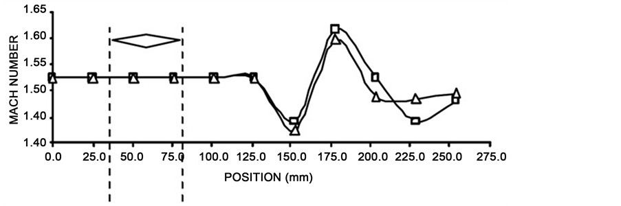
Figure 9. Comparison of Mach numbers obtained experimentally and numerically in supersonic flow.
Acknowledgements
The authors are grateful to SIP IPN for supporting part of this project through grant 20162113.
Cite this paper
Tellez, J.L.G., Hernandez-Martinez, E., Velazquez, M.T., Herrera, J.A.O. and Quinto-Diez, P. (2016) Eva- luating Oblique Shock Waves Characteristics on a Double-Wedge Airfoil. Engineering, 8, 862-871. http://dx.doi.org/10.4236/eng.2016.812078
References
- 1. Hsu, M.-H., Teng, W.-H. and Lai, C. (1998) Numerical Simulation of Supercritical Shockwave in Channel Contraction. Computers and Fluids, 27, 347-365.
https://doi.org/10.1016/S0045-7930(97)00068-6 - 2. Chen, S.X. (1992) Existence of Local Solution to Supersonic Flow past a Three-Dimensional Wing. Advances in Applied Mathematics, 13, 273-304.
http://www.sciencedirect.com/science/article/pii/019688589290013M https://doi.org/10.1016/0196-8858(92)90013-M - 3. Chen, G.-Q. and Feldman, M. (2005) Potential Theory for Shock Reflection by a Large-Angle Wedge. Proceedings of the National Academy of Sciences, 102, 15368-15372.
https://doi.org/10.1073/pnas.0505549102 - 4. Schaeffer, D.G. (1976) Supersonic Flow past a Nearly Straight Wedge. Duke Mathematical Journal, 43, 637-670.
https://doi.org/10.1215/S0012-7094-76-04351-9 - 5. Li, D. (2004) Analysis on Linear Stability of Oblique Shock Waves in Steady Supersonic Flow. Journal of Differential Equations, 207, 195-225.
http://www.sciencedirect.com/science/article/pii/S0022039604003559185 https://doi.org/10.1016/j.jde.2004.08.021 - 6. Abutabikh, M.I. (2015) Improving the Lift Characteristics of Supersonic Double Wedge Airfoil at Low Speed Using Passive-Active. Flow Controlling Methods, 33, 257-272.
- 7. Gupta, A. (2000) Supersonic Channel Airfoils for Reduced Drag. AIAA Journal, 38, 480-486.
https://doi.org/10.2514/3.14436 - 8. Kolluru, R. and Gopal, V. (2012) Numerical Study of Navier-Stokes Equations in Supersonic Flow over a Double Wedge Airfoil using Adaptive Grids. Proceedings of the 2012 COMSOL Conference, Bangalore, 1-6.
- 9. Shameem, B., Ebna, M. and Bause, M. (2013) Numerical Simulation of Fluid Structure Interaction (FSI) on a double wedge Airfoil based on Arbitrary Lagrangian-Eulerian Frameworks. The Workshop on Numerical Modelling of Grains/Fluid Flows, Lyon, November 2013.
- 10. Magri, V. and Kalkhoran, I.M. (2013) Numerical Investigation of Oblique Shock Wave/ Vortex Interaction. Computers and Fluids, 86, 343-356.
https://doi.org/10.1016/j.compfluid.2013.06.018 - 11. T.V.S.F. Garrido, J. and Tolentino, E. (2002) Experimental and Numerical Simulations of Oblique Shock Waves on Double Wedge Airfoil. The 10th International Symposium on Flow Visualization, Kyoto.