Energy and Power Engineering, 2013, 5, 363-367
doi:10.4236/epe.2013.54B070 Published Online July 2013 (http://www.scirp.org/journal/epe)
Analysis o n Effect of P a rameters of Different Wind
Generator on Power Grid Transient Stability*
Zhi-wei Wen1, Li Ding 2, Shi-en He3
1Gansu Electric Power Research Institute, Lanzhou, China
2Beijing Electric Research Institute of Economics and Technology, Beijing, China
3Wind Power Technology Center of Gansu Electric Power Corporation, Lanzhou, China
Email: wzw_8022@sina.com
Received January, 2013
ABSTRACT
To analyze the factors which affecting transient stability of power system, the dynamic model of doubly-fed induction
generator and direct-drive PM synchronous generator has been built using PSCAD. Impact of different wind farm inte-
gration on grid typically in China has been presented. The influence of the variations of transient reactance, negative
sequence reactance and rotary inertia on critical clearing time of power system transient stability is analyzed by
time-domain simulation. Mixture operation of DFIG and PMSG to optimize the stability of system has been analyzed
firstly. The digital simulation results show that doubly-fed induction wind turbines is a better choice to meet the re-
quirement of system instability due to large wind farm integration in comparison with direct-drive PM synchronous
wind turbines. With a rather large rotary inertia, the proper ratio of direct-drive PM synchronous wind turbines used in
wind farm could be comprehensive planning by optimized the stability of system. Analysis of this paper should be pro-
vided as academic reference for improving design of wind farm system.
Keywords: Wind Farm; Doubly-fed Induction Generator; Direct-drive PM Synchronous Generator; Parameter;
Transient Stability
1. Introduction
Unlike coal and other conventional resources used for
power generation, some renewable energy, such as wind
power, is random, intermittent and uncontrollable. Acci-
dent of grid or the tripping of wind farm will increase the
difficulty of system recovery with significant penetration
of wind power, even leading to the grid collapse. During
the past decades, wind power penetration limit has been
exceeded from about 5 percent to 20 percent in many
countries based on the reactive power compensators and
reinforcement of networks[1]. The choice of wind gen-
erator has been an important technical and economic
target to power system because analysis results show that
parameters of induction motor, such as stator reactance,
initial rotor slip, have influence on power system tran-
sient stability[2]. Effect of mechanical parameters of
induction generator (IG) and doubly-fed induction gen-
erator (DFIG) has been analyzed in conference[3]. Com-
parative analysis between IG, DFIG and direct-drive
permanent magnetism synchronous generator (PMSG) on
power system transient stability shows that variable
speed wind generator is a better choice to meet the re-
quirement of system in stability due to large wind farm
integration in comparison with wind generator of con-
stant speed[4]. Because the effect of converter, it is dif-
ficult to research the contrast between different type of
wind generator.
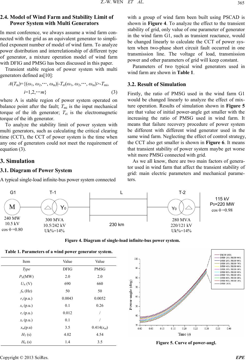
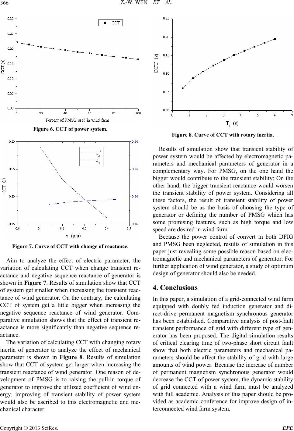
The main motive of this paper is to develop a simula-
tion platform of the integrated wind farm, and to evaluate
the performances of the transient characteristic with dif-
ferent t type of wind generator. Models of different type
of type of wind generator connected with grid are estab-
lished. Furthermore, some factors of generator which
affect the permissible power flow of the grid, such as
transient reactance, negative sequence reactance and ro-
tary inertia, have been studied. Comparative analyze of
the critical clearing time (CCT) have been proposed. Es-
pecially, mixture operation of DFIG and PMSG to opti-
mize the stability of system has been analyzed that can
provide fundamental data for future research of the wind
energy development.
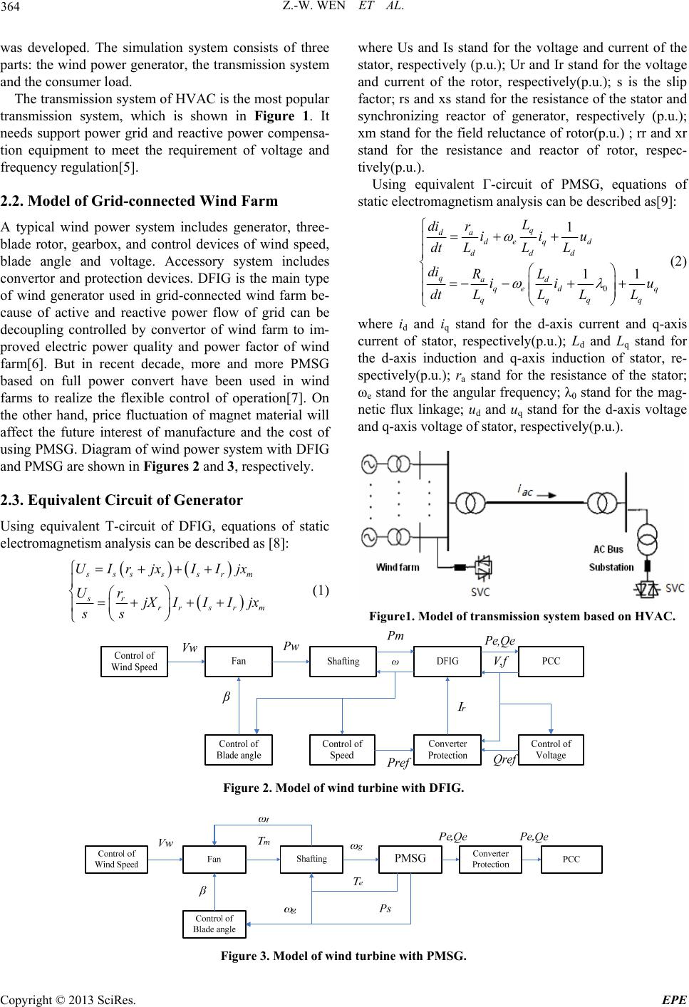
2. Model of Grid
2.1. Model of Grid-connected System
To investigating the transient stability of power system
connected with a large wind power, a simulation system
*This work was supported by Science and Technology Research Pro-
ect of Gansu Electric power Corporation (No. 2013101022).
Copyright © 2013 SciRes. EPE