Wireless Engineering and Technology
Vol.4 No.4(2013), Article ID:37948,6 pages DOI:10.4236/wet.2013.44025
Tri-Band Fractal Antennas for RFID Applications
![]()
1Department of Telecommunications Engineering, Higher Institute of Applied Engineering (IGA), Marrakesh, Morocco; 2Department of Electrical and Telecommunications Engineering, Royal Air Academy (ERA), Marrakesh, Morocco.
Email: reha.abdelati@gmail.com, a_ouladsaid@hotmail.com
Copyright © 2013 Abdelati Reha, Ahmed Oulad Said. This is an open access article distributed under the Creative Commons Attribution License, which permits unrestricted use, distribution, and reproduction in any medium, provided the original work is properly cited.
Received July 5th, 2013; revised August 9th, 2013; accepted August 27th, 2013
Keywords: Antenna; Fractals; RFID (Radio Frequency Identification); Multi-Band; Wide-Band
ABSTRACT
The RFID is a rapidly developing technology. It’s used in many applications such as logistics, ticketing, security, employee attendance record and others. Also, fractal technology is used in many areas, and recently in antenna design because it allows making multi-band and wide-band antennas. In this paper, two tri-band fractal antennas are studied for the Radio Frequency Identification (RFID) applications using the Method of Moment (MoM). The first one is designed for the RFID readers and it operates at 3.85 GHZ, 5.80 GHZ and 8.12 GHZ. The second one is designed for the RFID Tags and it operates at 3.94 GHZ, 5.65 GHZ and 8.20 GHZ.
1. Introduction
RFID stands for Radio Frequency Identification, a term that describes any system of identification wherein an electronic device that uses radio frequency or magnetic field variations to communicate is attached to an item. The two most talked-about components of an RFID system are the tag, which is the identification device attached to the item we want to track, and the reader, which is a device that can recognize the presence of RFID tags and read the information stored on them. The reader can then inform another system about the presence of the tagged items. The system with which the reader communicates usually runs software that stands between readers and applications. This software is called RFID middleware [1].
In a typical RFID system [2], passive tags are attached to an object such as goods, vehicles, humans, animals, and shipments, while a vertical/circular polarization antenna is connected to the RFID reader. The RFID reader and tag can radio-communicate with each other using a number of different frequencies, and currently most RFID systems use unlicensed spectrum. The common frequencies used are low frequency (125 KHz), high frequency (13.56 MHz), ultra high frequency (860 - 960 MHz/2.45 GHz), and microwave frequency (3.6/3.9/5.8/ 5.9/8.2 GHZ [3]). The typical RFID readers are able to read (or detect) the tags of only a single frequency but multimode readers are becoming cheaper and popular which are capable of reading the tags of different frequencies [4].
Several calculation methods are adopted to solve the Maxwell equations and then study the performance of the antennas. Among these, two are widely used in simulation software:
1) The method of moments (MoM) is used among others in FEKO software (an abbreviation derived from the German phrase FEldberechnung bei Körpern mit beliebiger Oberfläche (Field computations involving bodies of arbitrary shape)) [5].
2) The method of finite integral (FIT) is used in the software CST Microwave Studio (Computer Simulation Technology Microwave Studio) [6].
In this work, we use the FEKO software.
2. Fractal Antennas
The fractal antennas use fractals and self-similar models. Several studies show that we can easily make compact, multi-band and wide-band antennas, suitable for miniaturization and various applications such as RFID, WLAN (Wireless Local Area Network), WIMAX (WorldWide Interoperability for Microwave Access), WIFI (WIreless FIdelity) [7-9].
3. Antennas Geometry
3.1. Readers Antennas
The reader antenna is a fractal antenna 2nd iteration (Figure 1).
The antenna is fed by a Coplanar Waveguide (CPW). The antenna, the feeding point and the ground plane are on the same plane (Figure 2). Several studies have used this mode of feeding [10-13].
The antenna is designed on an FR4 substrate (relative dielectric constant = 4.3, thickness = 1.6 mm, loss tangent = 0.025). The overall dimension of the substrate is 40 × 60 mm².
The dimensions of the antenna are: L1 = 60 mm, L2 = 40 mm, L3 = 22 mm, H = 1.6 mm, H1 = 23 mm, H2 = 21 mm, H3 = 10 mm, W = 2.2 mm, S = 1 mm, G = 0.5 mm, q = 20˚, a = 40˚ (Figure 3).
3.2. Tag Antenna
The Tag antenna is a fractal antenna 3rd iteration (Figure 4).
The antenna is fed by a Coplanar Waveguide (CPW). The antenna, the feeding point and the ground plane are on the same plane (Figure 5).
The antenna is designed on an FR4 substrate (relative dielectric constant = 4.3, thickness = 1.6 mm, loss tangent = 0.025). The overall dimension of the substrate is 30 × 90 mm².
The dimensions of the antenna are: L1 = 90 mm, L2 = 30 mm, L3 = 10 mm, H = 1.6 mm, W = 2.4 mm, S = 1 mm, G = 1 mm (Figure 6).
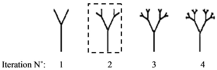
Figure 1. The first 4 iterations of the Tree-Fractal antenna.
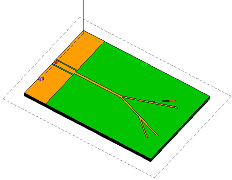
Figure 2. The Reader antenna fed by a coplanar waveguide (CPW).

Figure 3. Dimensions of the Reader Antenna [3].
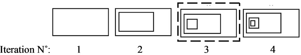
Figure 4. The first 4 iterations of the Rectangular-Fractal antenna.
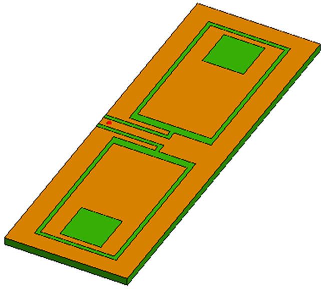
Figure 5. The Tag antenna fed by a coplanar waveguide (CPW).
4. Results and Discussions
4.1. Reader Antenna
The analysis of the S11 parameter (Figure 7) shows that the Reader antenna operates at f1 = 3.85 GHZ, f2 = 5.8 GHZ and f3 = 8.12 GHZ.
F1 = 3.85 GHZ
Around this frequency, the S11 parameter shown by Figure 8, we note that the bandwidth is 305 MHZ (from 3.69 GHz to 4 GHZ).
We also note that the gain of this antenna is 2.6 dBi for j = 90˚ and j = 60˚ as shown by Figure 9.
F2 = 5.8 GHZ
Around this frequency, the S11 parameter shown by Figure 10, we note that the bandwidth is 201 MHZ (from 5.743 GHZ to 5.944 GHZ)
We also note that the gain of this antenna is 1.7 dBi for j = 90˚ and j = 270˚ as shown by Figure 11.
F3 = 8.12 GHZ
Around this frequency, the S11 parameter shown by Figure 12, we note that the bandwidth is 289 MHZ (from
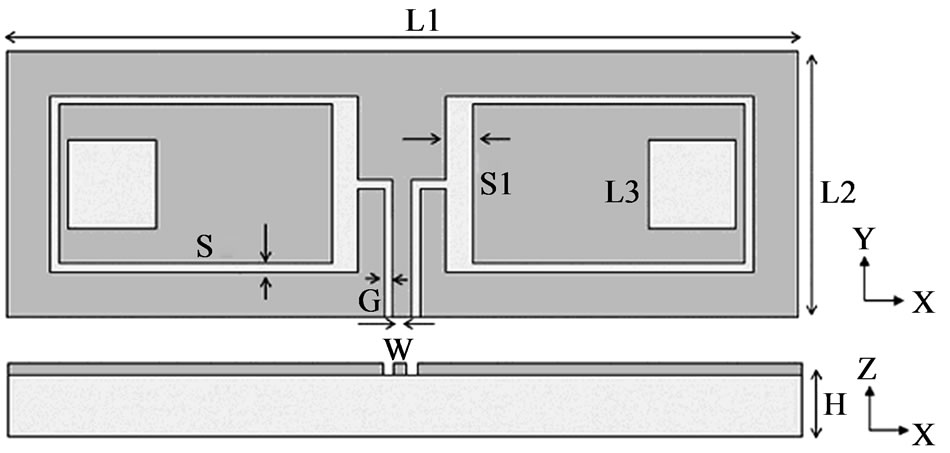
Figure 6. Dimensions of the Tag Antenna [3].
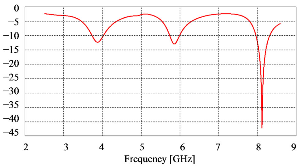
Figure 7. Simulated S11 versus frequency graph of the Reader antenna.

Figure 8. Evolution of S11 around the frequency f1 = 3.85 GHZ.

Figure 9. The gain of the antenna for f1 = 3.85 GHZ (for j = 90˚ and j = 60˚) – Gmax = 2.6 dBi.
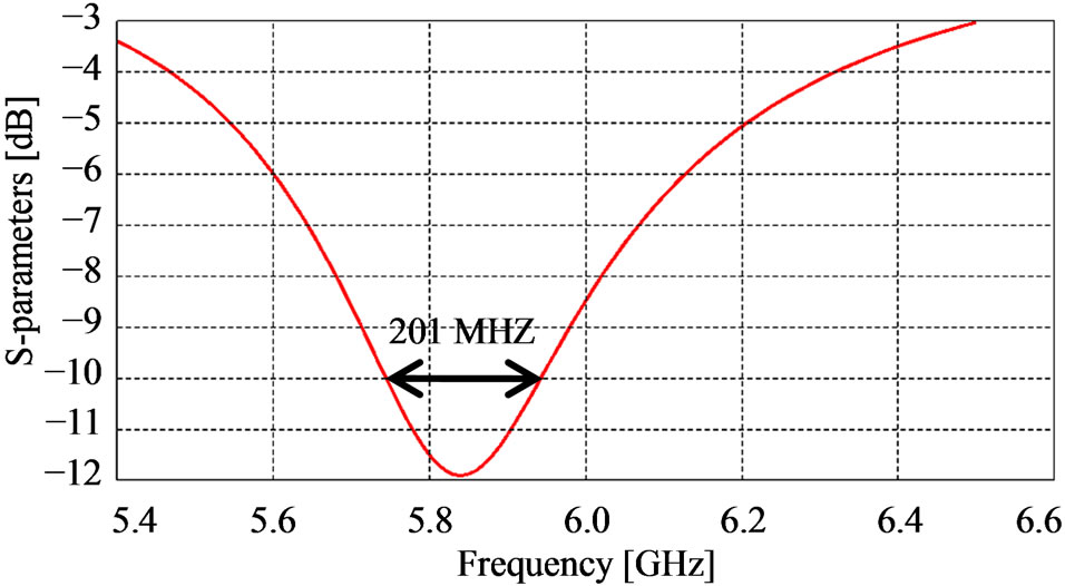
Figure 10. Evolution of S11 around the frequency f2 = 5.8 GHZ.
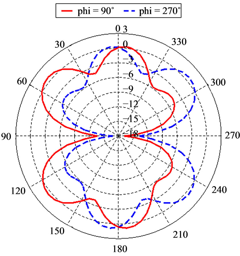
Figure 11. The gain of the antenna for f2 = 5.8 GHZ (for j = 90˚ and j = 270˚) – Gmax = 1.7 dBi.
7.989 GHZ to 8.278 GHZ).
We also note that the gain of this antenna is 2.7 dBi for j = 30˚ and j = 90˚ as shown by Figure 13.
4.2. Tag Antenna
The analysis of the S11 parameter (Figure 14) shows that the Tag antenna operates at f1 = 3.94 GHZ, f2 = 5.65
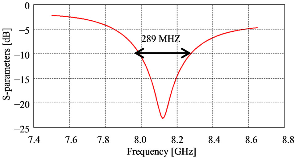
Figure 12. Evolution of S11 around the frequency f3 = 8.12 GHZ.
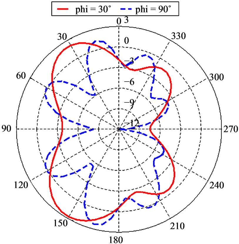
Figure 13. The gain of the antenna for f3 = 8.12 GHZ (for j = 30˚ and j = 90˚) – Gmax = 2.7 dBi.

Figure 14. Simulated S11 versus frequency graph of the Tag antenna.
GHZ and f3 = 8.2 GHZ.
F1 = 3.94 GHZ
Around this frequency, the S11 parameter shown by Figure 15, we note that the bandwidth is 165 MHZ (from 3.869 GHZ to 4.0348 GHZ).
We also note that the gain of this antenna is 3.8 dBi for j = 0˚ and j = 180˚ as shown by Figure 16.
F2 = 5.65 GHZ
Around this frequency, the S11 parameter shown by Figure 17, we note that the bandwidth is 149 MHZ (from 5.564 GHZ to 5.713 GHZ).
We also note that the gain of this antenna is 1.25 dBi for j = 0˚ and j = 180˚ as shown by Figure 18.
F3 = 8.2 GHZ
Around this frequency, the S11 parameter shown by Figure 19, we note that the bandwidth is 166 MHZ (from 8.101 GHZ to 8.267 GHZ).
We also note that the gain of this antenna is 2.65 dBi for j = 0˚ as shown by Figure 20.

Figure 15. Evolution of S11 around the frequency f1 = 3.94 GHZ.
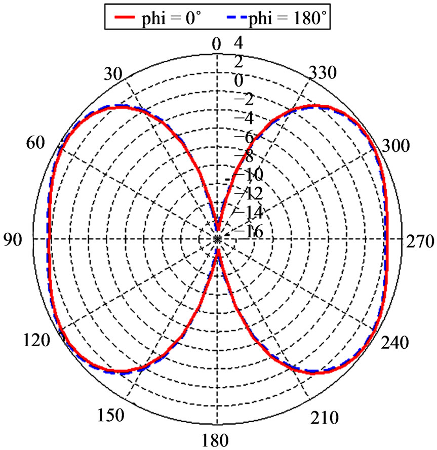
Figure 16. The gain of the antenna for f1 = 3.94 GHZ (for j = 0˚ and j = 180˚) – Gmax = 3.8 dBi.

Figure 17. Evolution of S11 around the frequency f2 = 5.65 GHZ.

Figure 18. The gain of the antenna for f2 = 5.65 GHZ (for j = 0˚ and j = 180˚) – Gmax = 1.25 dBi.
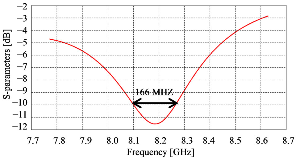
Figure 19. Evolution of S11 around the frequency f3 = 8.2 GHZ.
5. Read Range of the Antennas
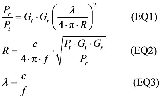
To calculate the read range of these antennas, we apply the First Transmission Equation (EQ1) which gives the relationship between the received power (Pr) as a func-

Figure 20. The gain of the antenna for f3 = 8.2 GHZ (for j = 0˚) – Gmax = 2.65 dBi.
tion of the transmitted power (Pt), the antennas gain (Gt, Gr) and free space loss which can be expressed in terms of the wavelength (l) and the distance between the antennas(R) .
For each one of the antennas, the read range calculation is done by taking a reference antenna of gain 3 dBi and minimum detectable power of 1 mW. The transmitting power is 4 W [3]. Therefore, we can build the table below (Table 1).
6. Comparison with other Methods of Calculation
This study has been done with The CST Microwave Studio which is based on the finite integral method (FIT) [3]. Our results are similar, but with small differences summarized in the Table 2.
Comparing these results, we note that:
• For the Reader, there is a small frequency lag of 0.25 GHZ (f1 FIT = 3.6 GHZ and f1 MoM = 3.85 GHZ)
• For the Tag, there is a small frequency lag of 0.25 GHZ (f2 FIT = 5.9 GHZ and f1 MoM = 5.65 GHZ)
7. Conclusions
The fractal antennas are preferred due to small size, light weight and multiband. This paper introduced RFID reader and tag antennas. The reader antenna exhibits a −10 dB bandwidth of 305 MHz at 3.85 GHz, 201 MHz at 5.8
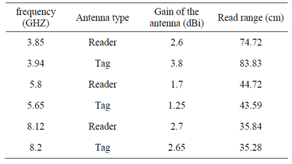
Table 1. Read range antennas.
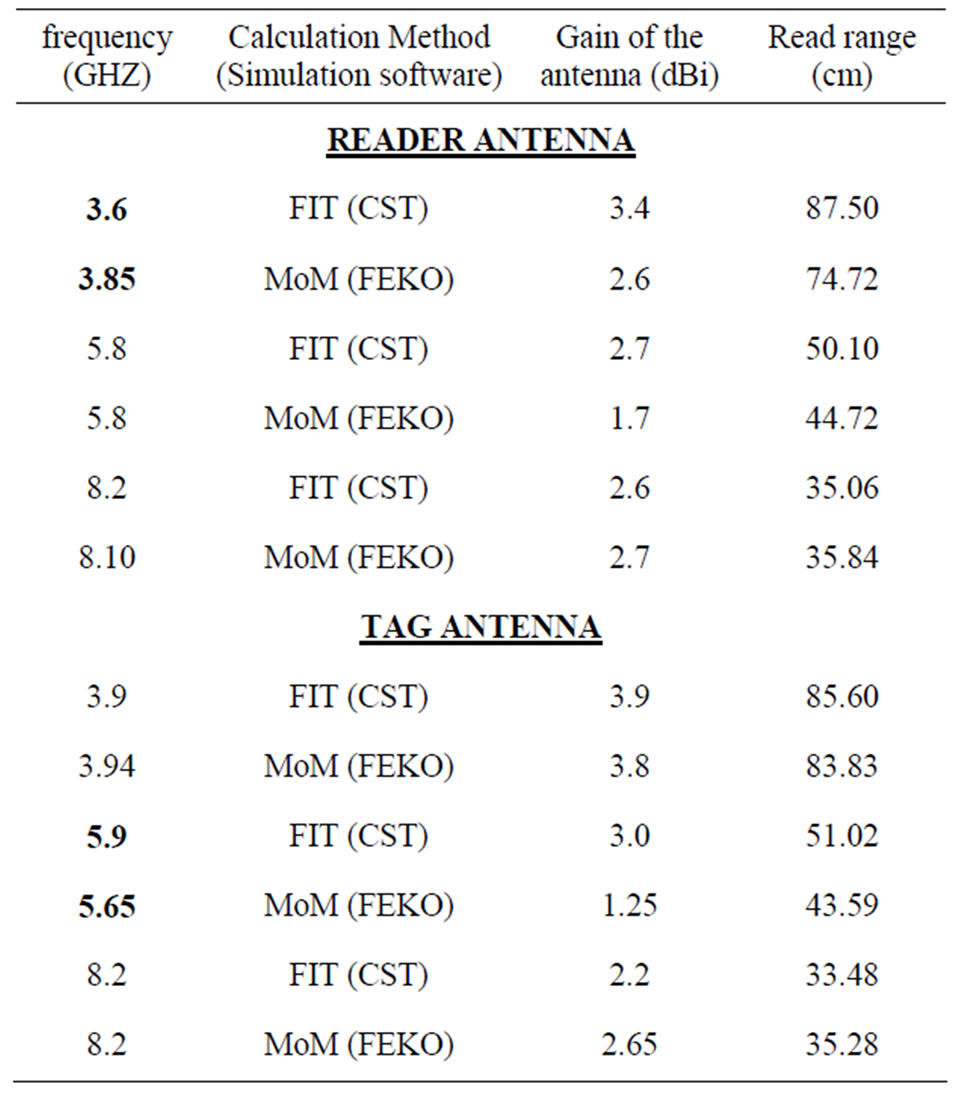
Table 2. Comparison of results between the two methods MoM and FIT.
GHz, and 289 MHz at 8.12 GHz. The tag antenna exhibits a −10 dB bandwidth of 165 MHz at 3.94 GHz, 149 MHz at 5.65 GHz, and 166 MHz at 8.2 GHz. The maximum read range obtained by the reader antenna is 74.72 cm, and 83.83 cm by the tag antenna.
By simulating the antennas using the Method of Moment (MoM) and comparing the results with another study using the method of finite integral (FIT), we find that the results are similar, even if there are small lags that are tolerable.
REFERENCES
- H. Bhatt and B. Glover, “RFID Essentials,” O’Reilly, Sebastopol, 2006.
- S. B. Miles, S. E. Sharma and J. R. Williams, “RFID Technology & Applications,” Cambridge University Press, New York, 2011.
- C. Varadhan, J. K. Pakkathillam, M. Kanagasabai, R. Sivasamy, R. Natarajan and S. K. Palaniswamy, “Triband Antenna Structures for RFID Systems Deploying Fractal Geometry,” IEEE Antennas and Wireless Propagation Letters, Vol. 12, 2013, pp. 437-440. http://dx.doi.org/10.1109/LAWP.2013.2254458
- G. O. Young, “Synthetic Structure of Industrial Plastics (Book Style with Paper Title and Editor),” In: J. Peters, Ed., Plastics, McGraw-Hill, New York, 1964, pp. 15-64.
- “FEKO 5.5 User’s Manual,” EM Software & Systems-S. A, 2009, pp. 1-1.
- B. Bieda and P. Słobodzian, “Efficiency of the IE-MoM Approach in the Analysis of Dielectric Bodies Embedded in a Cavity,” 2010 18th International Conference on Microwave Radar and Wireless Communications (MIKON), Vilnius, 14-16 June 2010, pp. 1-4.
- A. Mehdipour, L. Rosca, A. Sabek, C. Trueman and S. Hoa, “Full Composite Fractal Antenna Using Carbon Nanotubes for Multiband Wireless Applications,” IEEE Antennas Wireless Propagation Letters, Vol. 9, 2010, pp.891- 895. http://dx.doi.org/10.1109/LAWP.2010.2076342
- A. Ismahayati, P. J. Soh and R. Hadibah, “Design and Ana- lysis of a Multiband Koch Fractal Monopole Antenna,” 2011 IEEE International RF and Microwave Conference (RFM), Seremban, 12-14 December 2011, pp. 58-62.
- D. H. Werner and S. Ganguly, “An Overview of Fractal Antenna Engineering Research,” IEEE Antennas and Propagation Magazine, Vol. 45, No. 1, 2003, pp. 38-57.
- A. Mak, C. R. Rowell, R. D. Murch and M. Chi-Lun, “Compact Multiband Planar Antenna for 2.4/3.5/5.2/5.8- GHz Wireless Applications,” IEEE Antennas Wireless Propagation Letters, Vol. 11, 2012, pp. 144-147. http://dx.doi.org/10.1109/LAWP.2012.2185915
- D. C. Chang, B. H. Zeng and J. Liu, “CPW-Fed Circular Fractal Slot Antenna Design for Dual-Band Applications,” IEEE Transactions on Antennas and Propagation, Vol. 56, No. 12, 2008, pp. 3630-3637. http://dx.doi.org/10.1109/TAP.2008.2007279
- J. H. Gu, S. S. Zhong, L. L. Xue and Z. Sun “Dual-Band Monopole Antenna for 2.45/5.8 GHz RFID Applications,” 2008 China-Japan Joint Microwave Conference, Shanghai, 10-12 September 2008, pp. 133-135.
- B. D. Bala, M. K. A. Rahim, N. A. Murad, M. F. Ismail and H. A. Majid, “Design and Analysis of Metamaterial Antenna Using Triangular Resonator,” 2012 Asia-Pacific Microwave Conference Proceedings (APMC), Kaohsiung, 4-7 December 2012, pp. 577-579.