American Journal of Analytical Chemistry
Vol.10 No.08(2019), Article ID:94397,20 pages
10.4236/ajac.2019.108022
Separation of Formate Ion from a Catalytic Mixture after a Hydrogenation Process of Bicarbonate Ion and Generation of Formic Acid—The Last Stage of the Formic Acid Cycle
Ziv Treigerman*, Yoel Sasson
Institute of Chemistry, The Hebrew University of Jerusalem, Jerusalem, Israel

Copyright © 2019 by author(s) and Scientific Research Publishing Inc.
This work is licensed under the Creative Commons Attribution International License (CC BY 4.0).
http://creativecommons.org/licenses/by/4.0/


Received: July 4, 2019; Accepted: August 16, 2019; Published: August 19, 2019
ABSTRACT
Formic acid is recognized as a promising hydrogen carrier. It readily decomposes to release hydrogen (and carbon dioxide) in the presence of apposite catalysts. The main deficiency of this practice is that the reverse reaction, the hydrogenation of carbon dioxide to formic acid is an uphill reaction necessitating extreme conditions. Carbon dioxide should be converted to bicarbonate salts since their hydrogenation is reasonable for storing hydrogen. The related approach has a drawback as formate salts are produced. The latter has lower weight percentage of hydrogen and they must be converted to formic acid. The goals of our research were to separate formate salt from the reaction mixture and to convert it to formic acid. In this paper, we present a process that combines the advantages of both methodologies—formic acid is the carrier, but the hydrogen is charged to a bicarbonate ion. This stage completes the formic acid cycle (FAC), which could operate as a continuous process for the production and storage of hydrogen. Additional research, including proper rescaling and optimization, should be carried out in order to assess the potential of such a process as a basis for replacing the present day combustion of fossil fuels with hydrogen usage in fuel cells.
Keywords:
Green Chemistry, Hydrogen Storage, Ion Exchange, Separation Process

1. Introduction
Fossil fuels such as coal, petroleum and natural gas are widely used for generating electricity. Over the years, scientists have sought alternatives to these fuels due to their unsustainability [1] [2] [3] [4] (overuse of non-renewable resources) and the environmental damage caused by their utilization [5] . Hydrogen is the ultimate clean fuel; its chemical energy is converted to electricity in fuel cells—generating water without any polluting emissions. Nonetheless, the drawback of using elementary hydrogen as a fuel derives from its high flammability and very low density. These attributes have led researchers to scrutinize hydrogen carriers which release hydrogen gas under mild conditions. Many substances have been proposed for hydrogen storage [6] - [18] however, most reported solutions for storing hydrogen had a major downside in the reverse reaction which is typically not spontaneous and consumes large amounts of energy [19] [20] . Formic acid which contains 4.4% w/w of hydrogen and has a volumetric capacity of 53 gH2/L and a density of 1.22 g/cm3, was found as a substrate for hydrogen storage as its energy density is 1.77 kWh/L while most of the 700 bar hydrogen tanks exhibit only 1.4 kWh/L [21] . The dehydrogenation reaction of formic acid takes place in the presence of various homogeneous catalysts under mild conditions [22] - [43] (Equation (1)).
(1)
For the hydrogen storage process, the essential substrate is carbon dioxide [41] [44] - [54] . As the hydrogenation process without a basic medium is problematic, the product in the mentioned medium is formate ion and not pure formic acid. Noteworthy hydrogen carriers found to be practical for both charge/discharge processes are formic acid salts such as potassium and sodium formate. Nonetheless, formate salts contain only 2.35% and 1.98% w/w of hydrogen respectively (HCOONa/H2O and HCOOK/H2O). The inorganic formic acid salts react with water, generating bicarbonate salts [55] [56] (Equation (2)).
(2)
The hydrogenation process using bicarbonate ion as a substrate for storing hydrogen producing formate salts was investigated by utilizing different catalysts [32] [55] [57] - [64] (Equation (3)).
(3)
The combination of hydrogen generation from formate salts and hydrogenation of bicarbonate salts can create a system, based on the formate-bicarbonate cycle (FBC) [55] [60] [65] [66] [67] which is presented in Figure 1.
The hydrogenation of the bicarbonate salts (Equation (3)) is favorable since it mostly occurs at lower pressures since carbon dioxide is not required in the reaction. In addition, the reaction’s thermodynamics indicate that the bicarbonate salts’ hydrogenation is preferred (ΔG0 = 32.9 kJ/mole for carbon dioxide reduction while ΔG0 = −0.72 kJ/mole for bicarbonate hydrogenation). Likewise, the bicarbonate salts are easy to handle and require simple storage and transportation [22] [68] [69] [70] . Thus, in our previous paper [71] , we described our research addressing the carbon dioxide capturing process by generating sodium

Figure 1. The FBC cycle.
carbonate utilizing sodium hydroxide and hydrogen peroxide. Sodium carbonate can be easily converted to sodium bicarbonate for the hydrogen storage process. The reaction that occurs between carbon dioxide with sodium hydroxide and hydrogen peroxide as reactants is shown by Equation (4).
(4)
Obviously, most of the catalytic hydrogen storage reactions produce formate ions since they occur in a basic medium. It is important to separate the latter from the catalytic mixture for generating formic acid as it contains a larger weight percentage of hydrogen. Furthermore, the hydrogenation reaction of carbon dioxide requires high pressure of both carbon dioxide and hydrogen which decreases the feasibility of the process. Finally, the formic acid generation and separation must occur without the presence of the catalytic mixture as the catalyst can suffer from diminishing in its activity.
Researchers studied formate salt generation by a hydrogenation process in biphasic systems. The goal of these systems was to separate the product, the formate salts, from the catalytic mixture [72] [73] . For enhancing the hydrogen capacity by converting formate salts to formic acid, an acidification process is needed. The carbon dioxide reduction in such a system generates the formate salt in an amine solution. This evidence diminishes the feasibility of the system since the amount of amine decreases during the acidification process and requires replenishment in every cycle.
In our previous research [74] , we demonstrated the catalytic hydrogenation of sodium bicarbonate to sodium formate using a homogeneous Ru(II) catalyst. Herein, we attempt to add another step to the above-mentioned FBC cycle and convert the sodium formate into formic acid using solid-liquid anion exchange process followed by acidification. The modified formic acid catalytic cycle (FAC) is shown in Figure 2.
The main goal was to begin with the eco-friendly material—formic acid, and to produce it afterward without polluting the environment in comparison to fossil fuels which emit toxic and greenhouse gases when they are used.
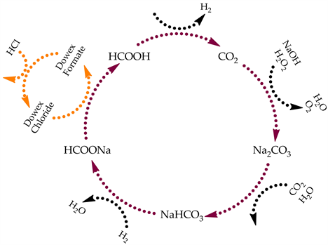
Figure 2. The suggested formic acid cycle.
2. Experimental Section
2.1. Materials
Sodium formate (Purum p.a., ≥98.0%) was purchased from Fluka Analytical supplier. The anion exchange materials were purchased from Sigma-Aldrich supplier. The anion exchange material, Dowex-Cl, is a strongly basic anion exchange resin (type I). The matrix consists of styrene-divinylbenzene and has 8% cross-linkage. Furthermore, there are trimethylamonnium chloride groups connected to the aromatic rings. The particle size is 100 - 200 mesh. The hydrochloric acid 1 M (Baker Analyzed, Volumetric Solution) was purchased from J.T. Baker supplier. All the materials were used without a re-purification.
2.2. Instruments
The formate and the chloride ions were analyzed and quantified by ion chromatography-Dionex LC20 Chromatography Enclosure with a pre-column-Dionex IonPac AG14, RFIC 4 × 50 mm Guard (Thermo) and a column-Dionex IonPac AS14 RFIC 4 × 250 mm Analytical (Thermo). Furthermore, the chloride ion was identified by potentiometric titrator-Metrohm Titrando 835 with an Ag Titrode 6.0430.100 Metrohm electrode. The concentration of the titrant Hg(NO3)2 was 0.01 N.
2.3. Typical Procedure for Separating Formate Ion from the Solution
The formate solution with a concentration of 0.5 M was prepared by dissolving sodium formate (3.4214 g, 0.050 mol) in water (100 mL). 10 mL of the solution was placed in a vial with Dowex-Cl (3.5103 g) and stirred for 1 h. Finally, the mixture was filtered and the solution was analyzed by IC afterward—30 µL of the solution was diluted to 100 mL with distilled water. 38.26% of formate ion was separated by the first ion exchange material. The solution after the substitution (5 mL) was introduced to a vial with Dowex-Cl (3.4826 g) and stirred again for 1 h. Then, the mixture was filtered, and the solution was analyzed by IC using the same procedure mentioned above. 46.90% of formate ion was separated by the second ion exchange material and a total of 67.21% were separated from the original solution.
At the beginning, the reaction was examined by IC apparatus after the formate solution was stirred with the ion exchange material for a longer time of 3 h in comparison to 1 h. Since no significant difference was observed, all the measurements were carried out after 1 h.
2.4. Typical Procedure for Generating Formic Acid and Regeneration of the Ion Exchange
The anion exchange materials from the latter separation experiment were stirred with a 1 M hydrochloric acid (10 mL) for 1 h. The solution was subsequently filtered with a glass microfiber filter and the chloride ion was analyzed by IC and potentiometric titration. The dilutions of the hydrochloric acid and the solutions after the regenerating process of the anion exchange material for the IC measurements were made as followed: 30 µL of the sample was diluted to 100 mL by a solution of 3.5 mM Na2CO3 and 2 mM NaHCO3 (the solution which was used as a buffer in the IC). For the first anion exchange material, 92.71% of the chloride ion replaced formate ion generating formic acid as was measured by IC and 98.73% was obtained by potentiometric titration. After the regeneration of the second anion exchange material, 91.33% of the chloride ion substituted the formate ion as was quantified by IC and 84.78% as measured by potentiometric titration.
3. Results and Discussion
The generation of formate ions for hydrogen storage was investigated in our laboratory as previously reported [74] . The hydrogenation reaction is described by (Equation (3)).
We have achieved yield > 80% and TON > 610 using an optimal hydrogen pressure of 20 bar at 70˚C. The ruthenium catalyst was stable even after four cycles.
As the product of the process mentioned above is the formate ion which has low hydrogen weight percentage in comparison to the formic acid, we developed a pathway for separating the formate ion from the catalytic mixture and acidified the latter afterward. The goal was achieved using an anion exchange material such as Dowex-Cl.
3.1. The Formate Ion Separation from the Solution
The method for measuring the number of moles of formate ion separated from the catalytic mixture after the hydrogenation process was as follows: The mixture was poured to a vessel containing the anion exchange substance and mixed for 1 h. The solution was subsequently filtered from the anion exchange material. Samples before and after the substitution reaction were examined and quantified by ion chromatography (IC) equipment. The results were 32% - 34% of replacing formate ion by chloride ion.
As the formate ion maximum concentration during the hydrogenation process is 0.5 M and the catalyst does not contain any negative charge, a solution of 0.5 M of sodium formate was studied during the exchange reaction. The results are summarized in Table 1.

Table 1. Sodium formate substitution using Dowex-Cl as an anion exchange.
Reaction conditions: All the sodium formate solutions were mixed at room temperature with the Dowex-Cl for 1 h. The solutions were then filtered and analyzed by IC. The substituted formate ion was calculated as the difference between the formate anion concentrations before and after the substitution utilizing the anion exchange. aRSD-relative standard deviation. b5 mL from the solution which was filtered before. cTotal adsorption after passing through two successive anion exchange materials.
The formate ion exchange process was examined using different concentrations of sodium formate with the formate ion concentration being monitored before and after the substitution occurred. Although as the initial sodium formate concentration increases, the adsorption percentage decreases, the amount of formate ion adsorbed by the anion exchange actually increases. For example, the formate ion adsorption percentage for initial concentration of 0.05 M was 76.1% (Table 1 Experiment 1) while for initial concentration of 0.50 M, an adsorption percentage of 39.9% (Table 1 Experiment 5) was calculated. Nevertheless, the amount of substituted formate ion for the lower initial concentration was equal to 0.038 M in comparison to 0.199 M for the higher initial concentration.
Several repetitions were carried out in each experiment, and it was found that a division of the anion exchange mass to two separation and successive systems, as is shown in Table 1 Experiment 7, increases the removal of formate ion from the solution.
3.2. The Ion Exchange Regeneration and the Formic Acid Production
The second goal after separating the formate ion from the solution was to extract the formate ion by acidifying the anion exchange and generating formic acid. As an additional result of this process, Dowex-Cl was regenerated for other separations. The percentage of the regeneration process was analyzed by ion chromatography and potentiometric titration (Table 2).
Table 2. Formic acid production and Dowex-Cl regeneration after rinsing with hydrochloric acid 1 M.
Reaction conditions: All the regeneration processes of the Dowex-Cl were made with 10 mL of hydrochloric acid 1 M at room temperature for 1 h. The solutions were then filtered. aRSD-relative standard deviation. bThe solutions were analyzed by potentiometric titration. cThe solutions were analyzed by IC.
The anion exchange regeneration process was carried out separately for each anion exchange material by hydrochloric acid. The acid was poured into the same anion exchange materials mentioned in Table 1 Experiment 7 and chloride ion substituted the formate ion which became formic acid. We monitored the chloride ion using ion chromatography equipment and potentiometric titration, and noted that the anion exchange material returned almost completely to its initial composition.
4. Conclusions
A method for generating formic acid by the separation of formate ion from its solution utilizing anion exchange material and acidifying it afterward was developed. This method should be appropriate for several processes such as the separation of formate ion from a homogeneous catalytic mixture and the production of formic acid for completing the formic acid cycle. The advantage of the proposed method is the regeneration of the anion exchange as it is carried out with the formic acid production simultaneously. We noticed that about 70% of the formate ion was substituted with the chloride anion in the first stage and after using hydrochloric acid, the Dowex-Cl was regenerated by releasing the formate ion as formic acid almost completely.
This research completes the formic acid cycle (FAC), each stage of which was presented in our papers. The FAC can operate in a continuous manner, producing and storing hydrogen as required. This method could be used for energy production through utilization in fuel cells. Further research is needed in order to make a large scale implementation and optimization of the proposed FAC methodology and full assessment of its potential for fossil fuels replacement.
Acknowledgements
This work was supported by the Israel Science Foundation Grant No. 1727/12. We would like to acknowledge the Analytical Chemistry Lab led by Dr. Carina Hazan at the Hebrew University of Jerusalem for their helpful assistance. Furthermore, we are grateful to Dr. Yakov Ronkin for his support and to Dr. Daniel Tysman for his proofreading of the manuscript.
Conflicts of Interest
The authors declare no conflicts of interest regarding the publication of this paper.
Cite this paper
Treigerman, Z. and Sasson, Y. (2019) Separation of Formate Ion from a Catalytic Mixture after a Hydrogenation Process of Bicarbonate Ion and Generation of Formic Acid—The Last Stage of the Formic Acid Cycle. American Journal of Analytical Chemistry, 10, 296-315. https://doi.org/10.4236/ajac.2019.108022
References
- 1. Owusu, P.A. and Asumadu-Sarkodie, S. (2016) A Review of Renewable Energy Sources, Sustainability Issues and Climate Change Mitigation. Cogent Engineering, 3, Article ID: 1167990. https://doi.org/10.1080/23311916.2016.1167990
- 2. Keles, S. (2011) Fossil Energy Sources, Climate Change, and Alternative Solutions. Energy Sources, Part A, 33, 1184-1195. https://doi.org/10.1080/15567030903330660
- 3. Armaroli, N. and Balzani, V. (2006) The Future of Energy Supply: Challenges and Opportunities. Angewandte Chemie International Edition, 46, 52-66. https://doi.org/10.1002/anie.200602373
- 4. Shafiee, S. and Topal, E. (2009) When Will Fossil Fuel Reserves Be Diminished? Energy Policy, 37, 181-189. https://doi.org/10.1016/j.enpol.2008.08.016
- 5. Liu, L., Cheng, S.Y., Li, J.B. and Huang, Y.F. (2007) Mitigating Environmental Pollution and Impacts from Fossil Fuels: The Role of Alternative Fuels. Energy Sources, Part A, 29, 1069-1080. https://doi.org/10.1080/15567030601003627
- 6. Ross, D. (2006) Hydrogen Storage: The Major Technological Barrier to the Development of Hydrogen Fuel Cell Cars. Vaccum, 80, 1084-1089. https://doi.org/10.1016/j.vacuum.2006.03.030
- 7. Shang, Y. and Chen, R. (2006) Hydrogen Storage via the Hydrolysis of NaBH4 Basic Solution: Optimization of NaBH4 Concentration. Energy Fuels, 20, 2142-2148. https://doi.org/10.1021/ef050363q
- 8. Li, H., Yang, Q., Chen, X. and Shore, S.G. (2014) Ammonia Borane, Past as Prolog. Journal of Organometallic Chemistry, 751, 60-66. https://doi.org/10.1016/j.jorganchem.2013.08.044
- 9. Chen, W., Ji, J., Duan, X., Qian, G., Li, P., Zhou, X., Chen, D. and Yuan, W. (2014) Unique Reactivity in Pt/CNT Catalyzed Hydrolytic Dehydrogenation of Ammonia Borane. Chemical Communications, 50, 2142-2144. https://doi.org/10.1039/c3cc48027e
- 10. Du, C., Ao, Q., Cao, N., Yang, L., Luo, W. and Cheng, G. (2015) Facile Synthesis of Monodisperse Ruthenium Nanoparticles Supported on Graphene for Hydrogen Generation from Hydrolysis of Ammonia Borane. International Journal of Hydrogen Energy, 40, 6180-6187. https://doi.org/10.1016/j.ijhydene.2015.03.070
- 11. Zhong, R.-Q., Zou, R.-Q., Nakagawa, T., Janicke, M., Semelsberger, T.A., Burrell, A.K. and Del Sesto, R.E. (2012) Improved Hydrogen Release from Ammonia-Borane with ZIF-8. Inorganic Chemistry, 51, 2728-2730. https://doi.org/10.1021/ic202562b
- 12. Patil, N.M., Bhosale, M.A. and Bhanage, B.M. (2015) Transfer Hydrogenation of Nitroarenes into Anilines by Palladium Nanoparticles via Dehydrogenation of Dimethylamine Borane Complex. RSC Advances, 5, 86529-86535. https://doi.org/10.1039/C5RA14944D
- 13. Zhang, Y.H.P. (2009) A Sweet Out-of-the-Box Solution to the Hydrogen Economy: Is the Sugar-Powered Car Science Fiction? Energy & Environmental Science, 2, 272-282. https://doi.org/10.1039/b818694d
- 14. Ye, X., Wang, Y., Hopkins, R.C., Adams, M.W.W., Evans, B.R., Mielenz, J.R. and Zhang, Y.H.P. (2009) Spontaneous High-Yield Production of Hydrogen from Cellulosic Materials and Water Catalyzed by Enzyme Cocktails. ChemSusChem, 2, 149-152. https://doi.org/10.1002/cssc.200900017
- 15. Nielsen, M., Alberico, E., Baumann, W., Drexler, H.-J., Junge, H., Gladiali, S. and Beller, M. (2013) Low-Temperature Aqueous-Phase Methanol Dehydrogenation to Hydrogen and Carbon Dioxide. Nature, 495, 85-89. https://doi.org/10.1038/nature11891
- 16. Lei, M., Pan, Y. and Ma, X. (2015) The Nature of Hydrogen Production from Aqueous-Phase Methanol Dehydrogenation with Ruthenium Pincer Complexes under Mild Conditions. European Journal of Inorganic Chemistry, 2015, 794-803. https://doi.org/10.1002/ejic.201403027
- 17. Fujii, T. and Saito, Y. (1991) Catalytic Dehydrogenation of Methanol with Ruthenium Complexes. Journal of Molecular Catalysis, 67, 185-190. https://doi.org/10.1016/0304-5102(91)85045-4
- 18. Prichatz, C., Alberico, E., Baumann, W., Junge, H. and Beller, M. (2017) Iridium-PNP Pincer Complexes for Methanol Dehydrogenation at Low Base Concentration. Chem-CatChem, 9, 1891-1896. https://doi.org/10.1002/cctc.201700015
- 19. Martin, O. and Perez-Ramirez, J. (2013) New and Revisited Insights into the Promotion of Methanol Synthesis Catalysts by CO2. Catalysis Science & Technology, 3, 3343-3352. https://doi.org/10.1039/c3cy00573a
- 20. Demirci, U.B., Akdim, O. and Miele, P. (2009) Ten-Year Efforts and a No-Go Recommendation for Sodium Borohydride for On-Board Automotive Hydrogen Storage. International Journal of Hydrogen Energy, 34, 2638-2645. https://doi.org/10.1016/j.ijhydene.2009.01.038
- 21. Eppinger, J. and Huang, K.-W. (2017) Formic Acid as a Hydrogen Energy Carrier. ACS Energy Letters, 2, 188-195. https://doi.org/10.1021/acsenergylett.6b00574
- 22. Mellmann, D., Sponholz, P., Junge, H. and Beller, M. (2016) Formic Acid as a Hydrogen Storage Material-Development of Homogeneous Catalysts for Selective Hydrogen Release. Chemical Society Reviews, 45, 3954-3988. https://doi.org/10.1039/C5CS00618J
- 23. Singh, A.K., Singh, S. and Kumar, A. (2016) Hydrogen Energy Future with Formic Acid: A Renewable Chemical Hydrogen Storage System. Catalysis Science & Technology, 6, 12-40. https://doi.org/10.1039/C5CY01276G
- 24. Fujita, E., Muckerman, J.T. and Himeda, Y. (2013) Interconversion of CO2 and Formic Acid by Bio-Inspired Ir Complexes with Pendent Bases. Biochimica et Biophysica Acta, 1827, 1031-1038. https://doi.org/10.1016/j.bbabio.2012.11.004
- 25. Himeda, Y. (2009) Highly Efficient Hydrogen Evolution by Decomposition of Formic Acid Using an Iridium Catalyst with 4,4’-Dihydroxy-2,2’-Bipyridine. Green Chemistry, 11, 2018-2022. https://doi.org/10.1039/b914442k
- 26. Wang, W.-H., Ertem, M.Z., Xu, S., Onishi, N., Manaka, Y., Suna, Y., Kambayashi, H., Muckerman, J.T., Fujita, E. and Himeda, Y. (2015) Highly Robust Hydrogen Generation by Bioinspired Ir Complexes for Dehydrogenation of Formic Acid in Water: Experimental and Theoretical Mechanistic Investigations at Different pH. ACS Catalysis, 5, 5496-5504. https://doi.org/10.1021/acscatal.5b01090
- 27. Hull, J.F., Himeda, Y., Wang, W.-H., Hashiguchi, B., Periana, R., Szalda, D.J., Muckerman, J.T. and Fujita, E. (2012) Reversible Hydrogen Storage Using CO2 and a Proton-Switchable Iridium Catalyst in Aqueous Media under Mild Temperatures and Pressures. Nature Chemistry, 4, 383-388. https://doi.org/10.1038/nchem.1295
- 28. Bielinski, E.A., Lagaditis, P.O., Zhang, Y., Mercado, B.Q., Würtele, C., Bernskoetter, W.H., Hazari, N. and Schneider, S. (2014) Lewis Acid-Assisted Formic Acid Dehydrogenation Using a Pincer-Supported Iron Catalyst. Journal of the American Chemical Society, 136, 10234-10237. https://doi.org/10.1021/ja505241x
- 29. Mellone, I., Gorgas, N., Bertini, F., Peruzzini, M., Kirchner, K. and Gonsalvi, L. (2016) Selective Formic Acid Dehydrogenation Catalyzed by Fe-PNP Pincer Complexes Based on the 2,6-Diaminopyridine Scaffold. Organometallics, 35, 3344-3349. https://doi.org/10.1021/acs.organomet.6b00551
- 30. Boddien, A., Mellmann, D., Gärtner, F., Jackstell, R., Junge, H., Dyson, P.J., Laurenczy, G., Ludwig, R. and Beller, M. (2011) Efficient Dehydrogenation of Formic Acid Using an Iron Catalyst. Science, 333, 1733-1736. https://doi.org/10.1126/science.1206613
- 31. Zell, T., Butschke, B., Ben-David, Y. and Milstein, D. (2013) Efficient Hydrogen Liberation from Formic Acid Catalyzed by a Well-Defined Iron Pincer Complex under Mild Conditions. Chemistry—A European Journal, 19, 8068-8072. https://doi.org/10.1002/chem.201301383
- 32. Jantke, D., Pardatscher, L., Drees, M., Cokoja, M., Herrmann, W.A. and Kühn, F.E. (2016) Hydrogen Production and Storage on a Formic Acid/Bicarbonate Platform Using Water-Soluble N-Heterocyclic Carbene Complexes of Late Transition Metals. ChemSusChem, 9, 2849-2854. https://doi.org/10.1002/cssc.201600861
- 33. Mellone, I., Peruzzini, M., Rosi, L., Mellmann, D., Junge, H., Beller, M. and Gonsalvi, L. (2013) Formic Acid Dehydrogenation Catalyzed by Ruthenium Complexes Bearing the Tripodal Ligands Triphos and NP3. Dalton Transactions, 42, 2495-2501. https://doi.org/10.1039/C2DT32043F
- 34. Mellone, I., Bertini, F., Peruzzini, M. and Gonsalvi, L. (2016) An Active, Stable and Recyclable Ru(II) Tetraphosphine-Based Catalytic System for Hydrogen Production by Selective Formic Acid Dehydrogenation. Catalysis Science & Technology, 6, 6504-6512. https://doi.org/10.1039/C6CY01219A
- 35. Boddien, A., Loges, B., Junge, H. and Beller, M. (2008) Hydrogen Generation at Ambient Conditions: Application in Fuel Cells. ChemSusChem, 1, 751-758. https://doi.org/10.1002/cssc.200800093
- 36. Fellay, C., Dyson, P.J. and Laurenczy, G. (2008) A Viable Hydrogen-Storage System Based on Selective Formic Acid Decomposition with a Ruthenium Catalyst. Angewandte Chemie, 120, 4030-4032. https://doi.org/10.1002/ange.200800320
- 37. Guan, C., Zhang, D.-D., Pan, Y., Iguchi, M., Ajitha, M.J., Hu, J., Li, H., Yao, C., Huang, M.-H., Min, S., Zheng, J., Himeda, Y., Kawanami, H. and Huang, K.-W. (2017) Dehydrogenation of Formic Acid Catalyzed by a Ruthenium Complex with an N,N’-Diimine Ligand. Inorganic Chemistry, 56, 438-445. https://doi.org/10.1021/acs.inorgchem.6b02334
- 38. Thevenon, A., Frost-Pennington, E., Weijia, G., Dalebrook, A.F. and Laurenczy, G. (2014) Formic Acid Dehydrogenation Catalysed by Tris(TPPTS) Ruthenium Species: Mechanism of the Initial “Fast” Cycle. ChemCatChem, 6, 3146-3152. https://doi.org/10.1002/cctc.201402410
- 39. Junge, H., Boddien, A., Capitta, F., Loges, B., Noyes, J.R., Gladiali, S. and Beller, M. (2009) Improved Hydrogen Generation from Formic Acid. Tetrahedron Letters, 50, 1603-1606. https://doi.org/10.1016/j.tetlet.2009.01.101
- 40. Pan, Y., Pan, C.-L., Zhang, Y., Li, H., Min, S., Guo, X., Zheng, B., Chen, H., Anders, A., Lai, Z., Zheng, J. and Huang, K.-W. (2016) Selective Hydrogen Generation from Formic Acid with Well-Defined Complexes of Ruthenium and Phosphorus-Nitrogen PN3-Pincer Ligand. Chemistry—An Asian Journal, 11, 1357-1360. https://doi.org/10.1002/asia.201600169
- 41. Boddien, A., Federsel, C., Sponholz, P., Mellmann, D., Jackstell, R., Junge, H., Laurenczy, G. and Beller, M. (2012) Towards the Development of a Hydrogen Battery. Energy & Environmental Science, 5, 8907-8911. https://doi.org/10.1039/c2ee22043a
- 42. Treigerman, Z. and Sasson, Y. (2017) Further Observation on the Mechanism of Formic Acid Decomposition by Homogeneous Ruthenium Catalyst. ChemistrySelect, 2, 5816-5823. https://doi.org/10.1002/slct.201701119
- 43. Onishi, N., Laurenczy, G., Beller, M. and Himeda, Y. (2018) Recent Progress for Reversible Homogeneous Catalytic Hydrogen Storage in Formic Acid and in Methanol. Coordination Chemistry Reviews, 373, 317-332. https://doi.org/10.1016/j.ccr.2017.11.021
- 44. Moret, S., Dyson, P.J. and Laurenczy, G. (2014) Direct Synthesis of Formic Acid from Carbon Dioxide by Hydrogenation in Acidic Media. Nature Communications, 5, 4017. https://doi.org/10.1038/ncomms5017
- 45. Jessop, P.G., Ikariya, T. and Noyori, R. (1994) Homogeneous Catalytic Hydrogenation of Supercritical Carbon Dioxide. Nature, 368, 231-233. https://doi.org/10.1038/368231a0
- 46. Munshi, P., Main, A.D., Linehan, J.C., Tai, C.C. and Jessop, P.G. (2002) Hydrogenation of Carbon Dioxide Catalyzed by Ruthenium Trimethylphosphine Complexes: The Accelerating Effect of Certain Alcohols and Amines. Journal of the American Chemical Society, 124, 7963-7971. https://doi.org/10.1021/ja0167856
- 47. Zhang, J.Z., Li, Z., Wang, H. and Wang, C.Y. (1996) Homogeneous Catalytic Synthesis of Formic Acid (Salts) by Hydrogenation of CO2 with H2 in the Presence of Ruthenium Species. Journal of Molecular Catalysis A: Chemical, 112, 9-14. https://doi.org/10.1016/1381-1169(96)00185-9
- 48. Muller, K., Sun, Y., Heimermann, A., Menges, F., Niedner-Schatteburg, G., van Wüllen, C. and Thiel, W.R. (2013) Structure-Reactivity Relationships in the Hydrogenation of Carbon Dioxide with Ruthenium Complexes Bearing Pyridinylazolato Ligands. Chemistry—A European Journal, 19, 7825-7834. https://doi.org/10.1002/chem.201204199
- 49. Gao, Y., Kuncheria, J.K., Jenkins, H.A., Puddephatt, R.J. and Yap, G.P.A. (2000) The Interconversion of Formic Acid and Hydrogen/Carbon Dioxide Using a Binuclear Ruthenium Complex Catalyst. Journal of the Chemical Society, Dalton Transactions, No. 18, 3212-3217. https://doi.org/10.1039/b004234j
- 50. Wesselbaum, S., Hintermair, U. and Leitner, W. (2012) Continuous-Flow Hydrogenation of Carbon Dioxide to Pure Formic Acid Using an Integrated scCO2 Process with Immobilized Catalyst and Base. Angewandte Chemie International Edition, 51, 8585-8588. https://doi.org/10.1002/anie.201203185
- 51. Filonenko, G.A., van Putten, R., Schulpen, E.N., Hensen, E.J.M. and Pidko, E.A. (2014) Highly Efficient Reversible Hydrogenation of Carbon Dioxide to Formate Using a Ruthenium PNP-Pincer Catalyst. ChemCatChem, 6, 1526-1530. https://doi.org/10.1002/cctc.201402119
- 52. Huff, C.A. and Sanford, M.S. (2013) Catalytic CO2 Hydrogenation to Formate by a Ruthenium Pincer Complex. ACS Catalysis, 3, 2412-2416. https://doi.org/10.1021/cs400609u
- 53. Thai, T.T., Therrien, B. and Süss-Fink, G. (2009) Arene Ruthenium Oxinato Complexes: Synthesis, Molecular Structure and Catalytic Activity for the Hydrogenation of Carbon Dioxide in Aqueous Solution. Journal of Organometallic Chemistry, 694, 3973-3981. https://doi.org/10.1016/j.jorganchem.2009.09.008
- 54. Sanz, S., Azua, A. and Peris, E. (2010) “(η6-arene)Ru(bis-NHC)” Complexes for the Reduction of CO2 to Formate with Hydrogen and by Transfer Hydrogenation with iPrOH. Dalton Transactions, 39, 6339-6343. https://doi.org/10.1039/c003220d
- 55. Boddien, A., Gärtner, F., Federsel, C., Sponholz, P., Mellmann, D., Jackstell, R., Junge, H. and Beller, M. (2011) CO2-“Neutral” Hydrogen Storage Based on Bicarbonates and Formates. Angewandte Chemie International Edition, 50, 6411-6414. https://doi.org/10.1002/anie.201101995
- 56. Wiener, H., Sasson, Y. and Blum, J. (1986) Palladium-Catalyzed Decomposition of Aqueous Alkali Metal Formate Solutions. Journal of Molecular Catalysis, 35, 277-284. https://doi.org/10.1016/0304-5102(86)87075-4
- 57. Wiener, H., Blum, J., Feilchenfeld, H., Sasson, Y. and Zalmanov, N. (1988) The Heterogeneous Catalytic Hydrogenation of Bicarbonate to Formate in Aqueous Solutions. Journal of Catalysis, 110, 184-190. https://doi.org/10.1016/0021-9517(88)90308-9
- 58. Federsel, C., Jackstell, R., Boddien, A., Laurenczy, G. and Beller, M. (2010) Ruthenium-Catalyzed Hydrogenation of Bicarbonate in Water. ChemSusChem, 3, 1048-1050. https://doi.org/10.1002/cssc.201000151
- 59. Liu, Q., Wu, L., Gülak, S., Rockstroh, N., Jackstell, R. and Beller, M. (2014) Towards a Sustainable Synthesis of Formate Salts: Combined Catalytic Methanol Dehydrogenation and Bicarbonate Hydrogenation. Angewandte Chemie International Edition, 53, 7085-7088. https://doi.org/10.1002/anie.201400456
- 60. Kothandaraman, J., Czaun, M., Goeppert, A., Haiges, R., Jones, J.P., May, R.B., Prakash, G.K.S. and Olah, G.A. (2015) Amine-Free Reversible Hydrogen Storage in Formate Salts Catalyzed by Ruthenium Pincer Complex without pH Control or Solvent Change. ChemSusChem, 8, 1442-1451. https://doi.org/10.1002/cssc.201403458
- 61. Chatterjee, D. and Sarkar, P. (2016) RuIII(edta) Catalyzed Hydrogenation of Bicarbonate to Formate. Journal of Coordination Chemistry, 69, 650-655. https://doi.org/10.1080/00958972.2015.1125476
- 62. Federsel, C., Boddien, A., Jackstell, R., Jennerjahn, R., Dyson, P.J., Scopelliti, R., Laurenczy, G. and Beller, M. (2010) A Well-Defined Iron Catalyst for the Reduction of Bicarbonates and Carbon Dioxide to Formates, Alkyl Formates, and Formamides. Angewandte Chemie International Edition, 49, 9777-9780. https://doi.org/10.1002/anie.201004263
- 63. Federsel, C., Ziebart, C., Jackstell, R., Baumann, W. and Beller, M. (2012) Catalytic Hydrogenation of Carbon Dioxide and Bicarbonates with a Well-Defined Cobalt Dihydrogen Complex. Chemistry—A European Journal, 18, 72-75. https://doi.org/10.1002/chem.201101343
- 64. Bertini, F., Mellone, I., Ienco, A., Peruzzini, M. and Gonsalvi, L. (2015) Iron(II) Complexes of the Linear rac-Tetraphos-1 Ligand as Efficient Homogeneous Catalysts for Sodium Bicarbonate Hydrogenation and Formic Acid Dehydrogenation. ACS Catalysis, 5, 1254-1265. https://doi.org/10.1021/cs501998t
- 65. Bi, Q.-Y., Lin, J.-D., Liu, Y.-M., Du, X.-L., Wang, J.-Q., He, H.-Y. and Cao, Y. (2014) An Aqueous Rechargeable Formate-Based Hydrogen Battery Driven by Heterogeneous Pd Catalysis. Angewandte Chemie International Edition, 53, 13583-13587. https://doi.org/10.1002/anie.201409500
- 66. Sordakis, K., Dalebrook, A.F. and Laurenczy, G. (2015) A Viable Hydrogen Storage and Release System Based on Cesium Formate and Bicarbonate Salts: Mechanistic Insights into the Hydrogen Release Step. ChemCatChem, 7, 2332-2339. https://doi.org/10.1002/cctc.201500359
- 67. Papp, G., Csorba, J., Laurenczy, G. and Joó, F. (2011) A Charge/Discharge Device for Chemical Hydrogen Storage and Generation. Angewandte Chemie International Edition, 50, 10433-10435. https://doi.org/10.1002/anie.201104951
- 68. Yasaka, Y., Wakai, C., Matubayasi, N. and Nakahara, M. (2010) Controlling the Equilibrium of Formic Acid with Hydrogen and Carbon Dioxide Using Ionic Liquid. The Journal of Physical Chemistry A, 114, 3510-3515. https://doi.org/10.1021/jp908174s
- 69. Bulushev, D.A. and Ross, J.R.H. (2018) Heterogeneous Catalysts for Hydrogenation of CO2 and Bicarbonates to Formic Acid and Formates. Catalysis Reviews—Science and Engineering, 60, 566-593. https://doi.org/10.1080/01614940.2018.1476806
- 70. Federsel, C., Jackstell, R. and Beller, M. (2010) State-of-the-Art Catalysts for Hydrogenation of Carbon Dioxide. Angewandte Chemie International Edition, 49, 6254-6257. https://doi.org/10.1002/anie.201000533
- 71. Treigerman, Z. and Sasson, Y. (2018) Carbon Dioxide Capturing for Purifying Hydrogen Generated by Formic Acid Decomposition. ChemistrySelect, 3, 2487-2491. https://doi.org/10.1002/slct.201703106
- 72. Guan, C., Pan, Y., Ang, E.P.L., Hu, J., Yao, C., Huang, M.-H., Li, H., Lai, Z. and Huang, K.-W. (2018) Conversion of CO2 from Air into Formate Using Amines and Phosphorus-Nitrogen PN3P-Ru(II) Pincer Complexes. Green Chemistry, 20, 4201-4205. https://doi.org/10.1039/C8GC02186D
- 73. Kothandaraman, J., Goeppert, A., Czaun, M., Olah, G.A. and Prakash, G.K.S. (2016) CO2 Capture by Amines in Aqueous Media and Its Subsequent Conversion to Formate with Reusable Ruthenium and Iron Catalysts. Green Chemistry, 18, 5831-5838. https://doi.org/10.1039/C6GC01165A
- 74. Treigerman, Z. and Sasson, Y. (2018) Generation and Quantification of Formate Ion Produced from Aqueous Sodium Bicarbonate in the Presence of Homogeneous Ruthenium Catalyst. ACS Omega, 3, 12797-12801. https://doi.org/10.1021/acsomega.8b00599
Supporting Information
1) Ion Chromatography:
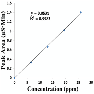
Figure S1. A calibration curve for formate ion.

Figure S2. A calibration curve for chloride ion.
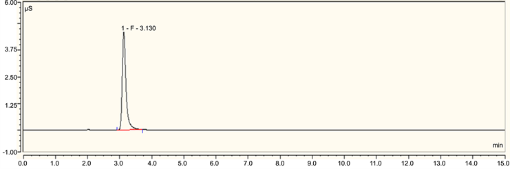
Figure S3. A typical ion chromatography spectrum of formate ion.
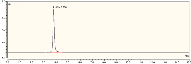
Figure S4. A typical ion chromatography spectrum of chloride ion.

Figure S5. An ion chromatography spectrum of formate ion before separating it from the solution utilizing an anion exchange material.

Figure S6. An ion chromatography spectrum of formate and chloride ions in the solution after the first substitution of formate ion with chloride ion in an anion exchange material.

Figure S7. An ion chromatography spectrum of formate and chloride ions in the solution after the second substitution of formate ion with chloride ion in a successive anion exchange material.

Figure S8. An ion chromatography spectrum of chloride ion in a hydrochloric acid solution.

Figure S9. An ion chromatography spectrum of formate and chloride ions in the solution after washing the first anion exchange material with hydrochloric acid for substituting chloride ion with formate ion (in a form of formic acid).

Figure S10. An ion chromatography spectrum of formate and chloride ions in the solution after washing the second anion exchange material with hydrochloric acid for substituting chloride ion with formate ion (in a form of formic acid).
2) Potentiometric Titration:

Figure S11. A potentiometric titration curve for chloride ion in hydrochloric acid solution titrating 0.01 N Hg(NO3)2 (blue curve: Voltage-Volume curve; purple curve: Equivalence point Recognition Criterion-ERC which is the first derivative of the titration curve).

Figure S12. A potentiometric titration curve for chloride ion in the solution after the first substitution of formate ion with chloride ion by ion exchange material titrating 0.01 N Hg(NO3)2 (blue curve: Voltage-Volume curve; purple curve: Equivalence point Recognition Criterion-ERC which is the first derivative of the titration curve).

Figure S13. A potentiometric titration curve for chloride ion in the solution after the second substitution of formate ion with chloride ion by a successive ion exchange material titrating 0.01 N Hg(NO3)2 (blue curve: Voltage-Volume curve; purple curve: Equivalence point Recognition Criterion-ERC which is the first derivative of the titration curve).

Figure S14. A potentiometric titration curve for chloride ion in the solution after washing the first anion exchange material with hydrochloric acid titrating 0.01 N Hg(NO3)2 (blue curve: Voltage-Volume curve; purple curve: Equivalence point Recognition Criterion-ERC which is the first derivative of the titration curve).
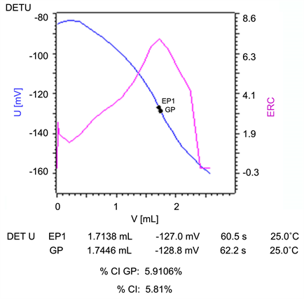
Figure S15. A potentiometric titration curve for chloride ion in the solution after washing the second anion exchange material with hydrochloric acid titrating 0.01 N Hg(NO3)2 (blue curve: Voltage-Volume curve; purple curve: Equivalence point Recognition Criterion-ERC which is the first derivative of the titration curve).