Journal of Electromagnetic Analysis and Applications
Vol.08 No.10(2016), Article ID:71119,14 pages
10.4236/jemaa.2016.810021
Nonlinear Terahertz Electromagnetic Waves in SrTiO3 Crystals under Focusing
Volodymyr Grimalsky, Svetlana Koshevaya, Jesus Escobedo-Alatorre, Margarita Tecpoyotl-Torres
CIICAp, Autonomous University of State Morelos (UAEM), Cuernavaca, Mexico

Copyright © 2016 by authors and Scientific Research Publishing Inc.
This work is licensed under the Creative Commons Attribution International License (CC BY 4.0).
http://creativecommons.org/licenses/by/4.0/


Received: September 7, 2016; Accepted: October 7, 2016; Published: October 10, 2016
ABSTRACT
The nonlinear waves of terahertz (THz) range are investigated in the paraelectric crystals SrTiO3 at the temperatures ~77 K. The frequency dispersion is important there. In the absence of a bias electric field the dominating nonlinearity is cubic. The frequency dispersion and nonlinearity correspond to existence of envelope solitons and the modulation instability (MI) of long input pulses, whereas in the transverse direction MI is absent. There exists a possibility to generate the regular sequences of short THz pulses due to MI in bounded SrTiO3 crystals. The focusing of input long pulses reduces the threshold of MI, increases the output amplitudes of the short pulses, and provides more stable generation of the short pulses. It is investigated the frequency multiplication of THz electromagnetic radiation in bounded paraelectric SrTiO3 when a bias electric field is applied. The dominating nonlinearity is quadratic there. The frequency dispersion and the transverse width of the input wave beams affect the generation of higher harmonics. It is possible to select the certain numbers of higher harmonics by means of the optimum length of the crystal, by the width of the beam of the input first harmonic, and by the focusing of the input first harmonic.
Keywords:
THz Waves, SrTiO3 Paraelectric, Nonlinearity, Frequency Dispersion, Focusing, Modulation Instability, Generation of Harmonics

1. Introduction
Over last 20 years the intensive assimilation of terahertz (THz) range (0.1 - 30 THz) took place [1] - [3] . The nonlinear dielectrics and semiconductors can be used as volume nonlinear materials in THz range. The ferroelectrics in the non-polar phase are utilized as the nonlinear dielectrics, so-called paraelectrics SrTiO3, KTaO3, and ceramics on their base [4] - [9] . The paraelectrics are characterized by high electrodynamic nonlinearity and low losses at low temperatures [6] - [9] . The crystalline SrTiO3 possesses high cubic nonlinearity and low losses in the lower part of THz range 0.1 - 1 THz at moderately low temperatures 50 - 90 K [6] - [8] . In a distinction from the microwave range, there exists the frequency dispersion in THz range when the frequency is near the soft mode frequency [7] [10] [11] . The soft mode is the lowest frequency of oscillations of the optical type of the crystalline lattice [7] [12] - [14] . The electromagnetic (EM) field dynamics is determined mainly by the soft mode dynamics [12] - [14] . In crystalline SrTiO3 the soft mode frequency decreases with the decrease of the temperature [7] . In the absence of a bias electric field the dominating nonlinearity is cubic and the nonlinear phenomena like self-action of input EM waves can occur [14] - [19] . The most interesting phenomenon is the modulation instability (MI) of long input EM pulses. When the bias electric field is present, the dominating nonlinearity is quadratic and the frequency multiplication in the volume SrTiO3 in microwave and THz ranges takes place [20] - [22] . Note that both the nonlinear self-action and frequency multiplication in THz range in SrTiO3 differ essentially from these processes in the microwave range. In the microwave range the frequency dispersion is practically absent. Thus, to realize MI, it is necessary to create the artificial dispersion, for instance, in dielectric waveguides [23] [24] . The harmonic generation in the microwave range results in the excitation of a vast number of harmonics > 20 and in the formation of shock EM waves, where the number of harmonics is limited by the wave dissipation only [9] .
In this paper the nonlinear EM phenomena in THz range in bounded crystalline SrTiO3 are investigated theoretically. The moderate cooling T ≈ 77 K is considered. When the bias electric field is absent, the self-action of input long pulses leads to the modulation instability (MI) and to the generation of the regular sequences of short THz pulses at the output of the crystal. The generation of higher harmonics is absent when the frequency of the input wave is ω > ωT/4, where ωT is the soft mode frequency. The focusing of the input THz wave results in the increase of the output amplitudes of the short pulses and in the stable generation of these pulses. When the bias electric field is present, the dominating nonlinearity is quadratic and the generation of higher harmonics occurs in SrTiO3. The frequency of the input EM wave should be chosen lower than in the previous case without bias. When the focusing of the input wave occurs, it is possible to excite the higher harmonics with very high efficiency. The input amplitudes are essentially smaller there, when compared with the case of the self-action.
2. Nonlinear Polarization in SrTiO3
The propagation of EM waves with the components Ex = E, Hy, Hz is considered along OZ axis within the layer of crystalline SrTiO3. The width of the layer is Ly, so the layer of SrTiO3 is at 0 < y < Ly, the dielectrics with moderate values of the permittivity ε1 ≤ 10 are at y < 0 and y > Ly. The structure is uniform along OX axis: ¶/¶x = 0. The dielectric nonlinearity in SrTiO3 is due to the nonlinear properties of the lattice polarization . The basic equations that describe the nonlinear EM wave propagation in paraelectric crystalline SrTiO3 are [7] :
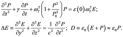 (1)
(1)
Here  is the soft mode frequency, which is in THz range for SrTiO3,
  is the lattice dissipation. The soft mode frequency increases with the increase of temperature T:
 . At the temperature T ≈ 77 K it is
 , and the static linear dielectric permittivity is
  [4] [6] [7] . For SrTiO3 the permittivity increases with the decrease of temperature [7] . In Equations (1) the parameter P0 determines the nonlinearity of the polarization. It is connected with the characteristic value of the electric field E0, where the nonlinearity is essential:
 . At the temperature T ≈ 77 K it is E0 = 60 kV/cm [7] . Because of small dissipation in SrTiO3, the nonlinearity manifests at the amplitudes of EM waves at least one order smaller than E0. In the linear case Equations (1) lead to the well-known expression of the complex dielectric permittivity [6] [7] :
 (2)
(2)
In the nonlinear stationary case Equations (1) result in the formula for the nonlinear permittivity [7] [8] :
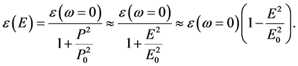 (3)
(3)
The expressions (3) for the static nonlinear permittivity are equivalent in the case of moderate electric fields . Namely this case is considered below.
Equations (1) are used below to describe the dynamics of the nonlinear waves both in the absence of a bias electric field, Section 3, and in the presence of it, Section 4.
3. Nonlinear Self-Action
3.1. Basic Equations
Here nonlinear EM wave processes are investigated in crystalline SrTiO3 without a bias electric field, where the cubic nonlinearity is dominating. From Equations (1) it is possible to obtain a single equation for the polarization:
 (4)
(4)
The nonlinearity is considered as moderate, so the method of slowly varying amplitudes is applied. The carrier frequency ω is higher than ωT/3, so there are no propagating resonant higher harmonics and the principal action of the cubic nonlinearity is the self-action. The solution of Equation (4) is searched as [15] [16] [24] - [26] :
 (5)
(5)
Here B(z, y, t) is a slowly varying amplitude. Equation (5) reflects a relation between the spectral representation and the slowly varying amplitude for the modulated wave. Integration in (5) with respect to  is within the narrow band near the central frequency ω, analogously for k:
 ,
, . The central frequency and the central wave number satisly the relation:
 (6)
(6)
Alter the substitution of Equation (5) into Equation (4) one can get the Equation:
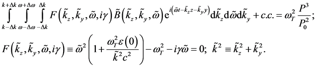 (7)
(7)
Here F = 0 is the linear dispersion relation; Equation (6) has been obtained from the linear dispersion relation when the dissipation g has been put to zero.
In the case of moderate nonlinearity Equation (6) can be reduced [24] - [26] to:
 (8)
(8)
The expansion of F has been used near the point . Thus, the following nonlinear parabolic equation has been derived:
 (9)
(9)
For a practical use, it is better to rewrite Equation (9) in terms of the electric field E:
 (10)
(10)
Here  is the slowly varying amplitude for the electric field.
 (11)
(11)
Equation (11) is the nonlinear Schrödinger equation [16] [17] [24] - [26] . The layer of SrTiO3 has a finite width Ly along OY axis. Equation (11) is added by the boundary conditions:
 (12)
(12)
Here A0 is the maximum amplitude of the input pulse; Ft(t) is a dependence of the long input pulse on t, which is close to rectangular; the parameter y0 determines the distribution of the input pulse along the transverse coordinate y, i.e. the width of input EM beam. The length of the crystal is Lz. The function M(y) is due to possible focusing of the input beam, as discussed below. Because the permittivities of the lateral dielectrics at y < 0 and y > Ly are much smaller than the permittivity of SrTiO3, the electric field does not penetrate into these dielectrics. But the nonlinear dynamics occurs within the crystal SrTiO3 and does not depend on the width Ly, but depends on the width of the EM beam, so an influence of the lateral boundaries is not essential. It is considered the case without reflections at the input z = 0 and the output z = Lz of the crystal, because the presence of reflections results in the generation of non-regular, or even chaotic, MI [19] .
The dynamics of MI has been investigated also under the focusing of the input wave. It is assumed that the input pulse is excited by the circular antenna of the radius of curvature R, as seen from Figure 1. In this case at the input the electromagnetic wave obtains the additional phase shift:
 (13)
(13)
where  is the distance from the input to the focus point,
  , k
, k
is the wave number. Correspondingly, in the plane z = 0 the input amplitude, Equation (12), obtains the multiplier . Due to the focusing

Figure 1. The focusing of the input wave by the circular antenna. Here R is the radius of curvature of the antenna. The phase shift is due to the variable distances D(y).
it is possible to reduce the thresholds of MI and to increase the amplitudes of the output short pulses.
In THz range the frequency dispersion is essential, it prevents the generation of higher harmonics. Moreover, in this paper the frequencies of higher harmonics in the absence of the bias electric field are higher that the soft mode frequency wT and do not propagate.
The signs of the dispersion and nonlinear coefficients coincide: . This corresponds to a possibility of propagation of pulse envelope solitons [15] [16] [24] . But for practical needs the realization of the modulation instability (MI) is more important, where it is possible to get regular sequences of short output pulses from input long pulses [19] . Note that the nonlinearity is defocusing in the transverse direction:
 . Therefore the nonlinear propagation of transversely bounded THz pulses in SrTiO3 differs from the propagation of the transversely uniform THz wave. The generation of the regular sequences of short THz pulses in the bounded SrTiO3 is the goal of this Section.
3.2. Simulations of Modulation Instability
For the numerical simulations the following parameters of crystalline SrTiO3 are the used: permittivity is  (T ≈ 77 K), the soft mode frequency is
 , the characteristic electric field is E0 = 60 kV/cm, the lattice dissipa- tion is
  [6] [7] . The carrier frequency of waves is chosen within the in terval
 ,
, . At higher frequencies the THz wave practically does not propagate in SrTiO3, because the group velocity is small and the wave dissipation is high there.
In Figures 2-6 the results of simulations of MI of long THz pulses in bounded SrTiO3 are presented. MI occurs when the amplitude of the input THz wave exceeds some threshold that depends on the carrier frequency. The wave amplitude is nor- malized to the value of the characteristic field E0. The time is normalized to . In all figures the part (a) is the general view; the part (b) is the de
tailedview of MI at a short temporal interval. The values of 
are given at the output of the crystal in the center of it. The shape of the input pulse in the center of the system y = Ly/2 is presented by the dot line. One can see that MI results in the generation of sequences of short pulses at the output of the crystal z = Lz near the center of the crystal y = Ly/2. In the part (c) there are the distributions of  for the time moment t/tn = 600.
In Figures 2-4 the carrier frequency is . In Figure 2 the focusing of the input pulse is absent whereas in Figure 3, Figure 4 the initially focused beam is used. One can see that under focusing MI occurs at smaller input amplitudes and the amplitudes of the output short pulses are higher than without focusing. Moreover, the generation of the sequences of short pulses is more stable under focusing of the input pulses. When the amplitudes of the long input pulses increase the output pulses get more complex shapes, compare Figure 3 and Figure 4(b).
At higher values of the input amplitudes A0 the dynamics of MI becomes non-regular and chaotic. Thus, the input amplitudes should be chosen properly to provide the regular sequences of short pulses at the output z = Lz.
At higher carrier frequencies ω > 0.6 ωT the dispersion coefficient |g1| increases and the group velocity vg decreases. Therefore, to observe MI at these frequencies the lengths of the crystal should be smaller than ones presented in Figures 2-4. In Figure 5, Figure 6 the results of simulations of MI are presented for the carrier frequency


 (a) (b) (c)
Figure 2. The generation of the regular sequence of THz pulses under MI without focusing of the input beam. The parameters are: the carrier frequency is ω = 2.5 × 10¹² s−1, the length of the crystal is Lz = 0.012 cm, the input amplitude is A0/E0 = 0.62.


 (a) (b) (c)
Figure 3. The generation of the regular sequence of THz pulses under MI with focusing of the input beam. The carrier frequency is w = 2.5 ´ 1012 s−1, the length of the crystal is Lz = 0.012 cm, the input amplitude is A0/E0 = 0.475. The radius of the curvature of the antenna is R = 0.032 cm.


 (a) (b) (c)
Figure 4. The same as in Figure 3, but a bit higher input amplitude is A0/E0 = 0.49.
 . The main problem is an appearance of the pedestal in the sequences of the output pulses. For instance, in Figure 5(b), this pedestal is 1/3 from the maximum amplitude of the output pulses. The focusing of the input long pulses makes possible not only to increase the amplitudes of the output short pulses but also to reduce the pedestal, Figures 5(b), Figure 6(b).
Thus, the absence of MI in the transverse direction plays a positive role for a stable generation of sequences of short output pulses under focusing of the input long pulse.
4. Generation of Higher Harmonics
4.1. Basic Equations
In this Section the nonlinear THz wave propagation is considered when the bias electric field Es is applied along OX axis:
 (14)
(14)
In this case the dominating nonlinearity is quadratic one. Ps is the constant polarization that corresponds to the bias field Es. Equations (1) are reduced to the equation for the variable part of the polarization:


 (a) (b) (c)
Figure 5. The generation of the regular sequence of THz pulses under MI without focusing of the input beam. The parameters are: the carrier frequency is w = 4.5 ´ 1012 s−1, the length of the crystal is Lz = 0.0015 cm, the input amplitude is A0/E0 = 0.52.


 (a) (b) (c)
Figure 6. The generation of the regular sequence of THz pulses under MI under focusing of the input beam. The parameters are: the carrier frequency is ω = 4.5 ´ 1012 s−1, the length of the crystal is Lz = 0.0015 cm, A0/E0 = 0.5. The radius of the curvature of the antenna is R = 0.0035 cm.
 (15)
(15)
Below the nonlinearity is assumed as moderate:  The stationary case of the harmonic generation is investigated. The method of slowly varying amplitudes is applied [25] - [27] here:
 (16)
(16)
The following relations should be satisfied: . Here k(wj) is the com- plex wave number for jth harmonic.
The set of coupled equations for Bj has been obtained:
 (17)
(17)
For applications it is better to use the slowly varying amplitudes for the electric field of EM waves:
 (18)
(18)
Equations (17) are rewritten in the equivalent form:
 (19)
(19)
Here Qs is determined from the Equation:
 (20)
(20)
The typical values of the bias electric field Es and the input amplitudes for the first harmonic are Es/E0 = 0.2 − 0.5, A10/E0 = 0.02 − 0.1, and therefore Qs ≈ Es. Equations (19) agree with [20] obtained by another approach, where EM waves were uniform in y direction. The typical values of the frequencies of the first harmonics are w1 = 1011 − 6 × 10¹¹ s−1. Higher harmonics are in the lower part of THz range.
The boundary conditions are similar to Equation (12), but for the purely stationary case:
 (21)
(21)
Here the multiplier M(y) is due to the focusing of the input first harmonic, see Equation (12) and Figure 1.
There is the principal difference of the generation of higher EM harmonics in THz range from the analogous process in the microwave range. In the microwave range the shock EM wave is formed in the volume crystal or in the metallic waveguide due to nonlinearity without the frequency dispersion. More than 20 harmonics are excited there; this number is limited by the wave dissipation [9] . In THz range the frequency dispersion is important and the number of harmonics is ≤6, see Figure 7. The harmonics of higher numbers are not excited because of the essential wave dispersion and,
thus, great mismatches , see Equations (19).
4.2. Selective Generation of Higher Harmonics
Numerical simulations of the stationary frequency multiplication of the input EM beams in SrTiO3 have demonstrated a high efficiency of the multiplication in the low frequency part of THz range. Below in all figures the amplitudes are normalized to the characteristic electric field E0 = 60 kV/cm. The frequency dispersion is important there. Our simulations have shown that the cubic nonlinearity does not affect the generation of higher harmonics, i.e. namely the quadratic nonlinearity is dominating when the bias electric field is applied. Really no more than 6 higher harmonics are excited.
In Figures 8-10 there are the typical results of simulations. In Figure 8 the input EM beam is without focusing. The bias electric field is . The input amplitude of the first harmonic is
 . The frequency of the first harmonic is
 . One can see that the maxima of higher harmonics do not exceed 20% from the input one. The maximum is realized for the 4th harmonic at the distance z = 0.5 cm.

Figure 7. Dependence of the linear wave number k1 (curve 1) and the mismatches Dk º kj ? jk1 for the 2nd- 5th harmonics (curves 2 - 5) on the frequency of the first harmonic ω.


 (a) (b) (c)
Figure 8. The excitation of higher harmonics without focusing. The frequency of the first harmonic is w1 = 0.25 ´ 1012 s−1. The input amplitude is A10/E0 = 0.05, the bias electric field is Es/E0 = 0.5. Part (a) is the distribution of |Aj(z)|2 in the center of the beam y = 0.25 cm; part (b) is the distribution |A1(z,y)|2 for the first harmonic; part (c) is |A4(z,y)|2 for the 4th harmonic.


 (a) (b) (c)
 (d) (e)
Figure 9. The same as in Figure 8, but the focusing of the input first harmonic takes place. The radius of the curvature of the antenna is R = 0.38 cm. Part (a) is the distribution of |Aj(z)|2 in the center of the beam y = 0.25 cm; part (b) is the distribution |A1(z,y)|2 for the first harmonic; part (c) is |A3(z,y)|2 for the 3rd harmonic; part (d) is |A4(z,y)|2 for the 4th harmonic; part (e) is |A5(z,y)|2 for the 5th harmonic.


 (a) (b) (c)
Figure 10. The excitation of higher harmonics in the case of focusing of the first harmonic w1 = 0.4 ´ 1012 s−1. The radius of the antenna is R = 0.27 cm. Part (a) is the distribution of |Aj(z)|2 in the center of the crystal y = 0.2 cm, part (b) is the distribution |A1(z,y)|2 for the first harmonic; part (c) is |A2(z,y)|2 for the 2nd harmonic.
To increase the efficiency of the generation of higher harmonics it is possible by means of the focusing of the input EM beam. In Figure 9 the parameters are the same as in Figure 8, but the focusing is applied. The radius of the curvature of the antenna is R = 0.38 cm. By means of the focusing there is a possibility to select the maxima of the higher harmonics. For instance, the 3rd harmonic has the maximum at the length z = 0.4 cm, whereas the 4th one has its maximum at z = 0.35 cm, the 5th one has its maximum at z = 0.32 cm. One can see that the maximum of the 3rd harmonic exceeds the maximum of the input first one.
In Figure 10 the carrier frequency of the first harmonic is higher than in Figure 8, Figure 9, w1 = 0.4 × 10¹² s−1, the bias field and the input amplitudes are the same ,
, . The radius of curvature of the antenna is R = 0.27 cm. The input beam is a bit narrower than in Figure 8, Figure 9.
Near the focus for the first harmonic the excited 2nd harmonic reaches the maximum value, which has the intensity 5 times higher than the input first harmonic. The mutual nonlinear focusing of the first and the second harmonics is known in optics [27] . But here the increased efficiency of the excitation of the second harmonic occurs when also the third and higher harmonics are also excited during the nonlinear interaction and take the part of the input energy of the first harmonic.
Thus, the focusing of the input first harmonic may increase the efficiency of the generation of higher harmonics of THz range in a bounded nonlinear dielectric SrTiO3.
5. Conclusions
In the lower frequency part of the terahertz range at frequencies f = 0.4 - 0.8 THz ( ) near the soft mode frequency fT ≈ 1 THz the bounded crystalline strontium titanate SrTiO3 can be used for the generation of the regular sequences of terahertz pulses under the nitrogen levels of cooling T ~ 77 K. The signs of the wave dispersion and the cubic nonlinearity correspond to a possibility of the modulation instability of long input pulses. The diffraction prevents the modulation instability in the transverse direction. The modulation instability leads to the generation of regular sequences of short THz pulses at the output of the bounded crystal SrTiO3, which is interesting for practical needs. The durations of short output pulses are of about 5 - 20 ps. The modulation instability can be observed under the input amplitudes of electromagnetic waves, when the nonlinearity is moderate. The focusing of the input pulses can reduce the threshold of the modulation instability and increase the output amplitudes of the short pulses. Also the generation of regular sequences of short pulses is more stable under focusing than without it.
The bounded crystals SrTiO3 can be used for the frequency multiplication in the low frequency part of the terahertz range at the temperatures T ~ 77 K. The bias electric field should be applied there and the quadratic nonlinearity is dominating. The frequency dispersion is important in the terahertz range. Really no more than 6 higher harmonics are excited. There is a possibility to increase the efficiency of the frequency multiplication by means of the focusing of the input first harmonic. Also it is possible to select the maxima of higher harmonics by means of the optimization of the length of the crystal and the radius of curvature of the exciting antenna.
Acknowledgements
The authors thank to SEP-CONACyT (Mexico) for a partial support of our work.
Cite this paper
Grimalsky, V., Ko- shevaya, S., Escobedo-Alatorre, J. and Tecpoyotl-Torres, M. (2016) Nonlinear Terahertz Electromagnetic Waves in SrTiO3 Crystals under Focusing. Journal of Electromagnetic Analysis and Applications, 8, 226-239. http://dx.doi.org/10.4236/jemaa.2016.810021
References
- 1. Lee, Y.-S. (2009) Principles of Terahertz Science and Technology. Springer, N.Y.
- 2. Perenzoni, M. and Paul, D.J. (2014) Physics and Applications of Terahertz Radiation. Springer, N.Y.
http://dx.doi.org/10.1007/978-94-007-3837-9 - 3. Ward, J.S., Chattopadhyay, G., Gill, J., Javadi, H., Lee, C., Lin, R., Maestrini, A., Maiwald, F., Mehdi, I., Schlecht, E. and Siegel, P. (2008) Tunable Broadband Frequency-Multiplied Terahertz Sources. Infrared, Millimeter and Terahertz Waves, 2008, IRMMW-THz 2008, 33rd International Conference, Caltech, 15-19 September 2008, 1-3.
http://dx.doi.org/10.1109/icimw.2008.4665437 - 4. Rez, I.S. and Poplavko, Yu.M. (1989) Dielectrics. Basic Properties and Applications in Electronics. Radio and Svyaz’, Moscow. (In Russian)
- 5. Poplavko, Yu.M., Pereverzeva, L.P., Voronov, S.O. and Yakimenko, Yu.I. (2007) Physical Material Science. Vol. 2, Dielectrics. KPI Publ., Kiev. (In Ukrainian)
- 6. Gevorgian, S. (2009) Ferroelectrics in Microwave Devices, Circuits and Systems. Springer, N.Y.
http://dx.doi.org/10.1007/978-1-84882-507-9 - 7. Vendik, O.G. (1979) Ferroelectrics in Microwave Technology. Sov. Radio, Moscow. (In Russian)
- 8. Buzin, I.M., Ivanov, I.V., Belokopytov, G.V., Sychev, V.M. and Chuprakov, V.F. (1981) Low-Temperature Ferroelectrics: Dielectric Permittivity, Losses, and Parametric Interactions at Ultrahigh Frequencies. Izvestiya Vysshikh Uchebnykh Zavedenii, Fizika, 24, 6-28. (English Transl. Soviet Physics Journal)
- 9. Gassanov, L.G., Koshevaya, S.V., Narytnik, T.N. and Omel’yanenko, M.Yu. (1978) Parametric and Nonlinear Interaction of Electromagnetic Waves in Paraelectrics. Izvestiya Vysshikh Uchebnykh Zavedenii, Radioelektronika, 21, 56-63. (English Transl. Radioelectronics and Communications Systems)
- 10. Kamarás, K., Barth, K.L., Keilmann, F., Henn, R., Reedyk, M., Thomsen, C., Cardona, M., Kircher, J., Richards, P.L. and Stehle, J.L. (1995) The Low Temperature Infrared Optical Functions of SrTiO3 Determined by Reflectance Spectroscopy and Spectroscopic Ellipsometry. Journal of Applied Physics, 78, 1235-1240.
http://dx.doi.org/10.1063/1.360364 - 11. Yashchyshyn, Y., Godziszewski, K., Bajurko, P., Modelski, J., Szafran, M., Bobryk, E., Pawlikowska, E., Tarapata, G., Weremczuk, J. and Jachowicz, R. (2013) Tunable Ferroelectric Ceramic-Polymer Composites for Sub-THz Applications. 43rd European Microwave Conference, Nuremberg, 7-10 October 2013, 676-679.
- 12. Rabe, K.M., Ahn, C.H. and Triscone, J.-M. (2007) Physics of Ferroelectrics. A Modern Perspective. Springer, N.Y.
- 13. Lines, M.E. and Glass, A.M. (1977) Principles and Applications of Ferroelectric and Related Materials Clarendon Press, Oxford.
- 14. Strukov, B.A. and Levanyuk, A.P. (1998) Ferroelectric Phenomena in Crystals. Springer, N.Y.
http://dx.doi.org/10.1007/978-3-642-60293-1 - 15. Kivshar, Y.S. and Agrawal, G.P. (2003) Optical Solitons. From Fibers to Photonic Crystals. Academic Press, N.Y.
- 16. Rabinovich, M.I. and Trubetskov, D.I. (1989) Oscillations and Waves in Linear and Nonlinear Systems. Kluwer, Dordrecht.
- 17. Kalinikos, B.A., Kovshikov, N.G. and Slavin, A.N. (1988) Envelope Solitons and Modulational Instability of Dipole-Exchange Spin Waves in YIG Films. Soviet Physics—JETP, 67, 303-312.
- 18. Dudko, G.M. and Filimonov, Y.A. (1989) Development of Modulation Instability of Magnetostatic Waves in Ferrite Films. Pis’ma v Zhurnal Tekhnicheskoi Fiziki, 15, 55-60.
- 19. Rapoport, Y.G., Grimalsky, V.V., Koshevaya, S.V. and Melendez-Isidoro, D.L. (2015) Modulation Instability of Terahertz Electromagnetic Pulses in SrTiO3 Paraelectric. 2015 IEEE 35th International Conference on Electronics and Nanotechnology (ELNANO), Kyiv, 21-24 April 2015, 128-131.
http://dx.doi.org/10.1109/ELNANO.2015.7146851 - 20. Zamudio-Lara, A., Koshevaya, S.V., Grimalsky, V.V. and Yañez-Cortes, F. (2015) Frequency Multiplication of Terahertz Radiation in the Crystals of Strontium Titanate Paraelectric. Radioelectronics and Communications Systems, 58, 411-416.
http://dx.doi.org/10.3103/S0735272715090034 - 21. Gassanov, L.G., Koshevaya, S.V. and Omel’yanenko, M.Y. (1980) On Frequency Multiplication in Paraelectrics. Radiotekhnika i Elektronika, 25, 1238-1243.
- 22. Koshevaya, S.V., Kononov, M.V. and Omel’yanenko, M.Y. (1985) An Influence of Dispersion in Waveguiding Systems with Cubically Nonlinear Dielectrics. Radioelectronics and Communications Systems, 28, 53-56.
- 23. Grimalsky, V.V. and Koshevaya. S.V. (1987) Automodulation Instability and Solitons in Ferroelectrics. Pis’ma v Zhurnal Tekhnicheskoi Fiziki, 11, 1070-1071.
- 24. Kodama, Y. and Hasegawa, A. (1987) Nonlinear Pulse Propagation in a Monomode Dielectric Guide. IEEE Journal of Quantum Electronics, 23, 510-524.
http://dx.doi.org/10.1109/JQE.1987.1073392 - 25. Bloembergen, N. (1965) Nonlinear Optics. WA Benjamin Inc., New York.
- 26. Weiland, J. and Wilhelmsson, H. (1977) Coherent Non-Linear Interaction of Waves in Plasmas. Pergamon Press, London.
- 27. Sukhorukov, A.P. (1988) Nonlinear Wave Interactions in Optics and Radiophysics. Nauka, Moscow. (In Russian)