Journal of Computer and Communications
Vol.03 No.06(2015), Article ID:56678,8 pages
10.4236/jcc.2015.36002
Numerical Investigation of Phase and Group Propagation of Time-Domain Signals in a Novel Band-Reject Metamaterial Ring Hybrid
Omar Siddiqui
College of Engineering, Taibah University, Madinah, Kingdom of Saudi Arabia
Email: omarsiddiqui2@gmail.com
Copyright © 2015 by author and Scientific Research Publishing Inc.
This work is licensed under the Creative Commons Attribution International License (CC BY).
http://creativecommons.org/licenses/by/4.0/


Received 5 April 2015; accepted 23 May 2015; published 26 May 2015
ABSTRACT
Phase and group propagation in metamaterial-based microwave components has always been intellectually challenging for students and engineers new to the area of periodic structures and metamaterials. This paper aims in tackling this important topic by studying the wave propagation in a metamaterial-based microwave device. Hence, the contribution of this paper is twofold. First, design of a novel metamaterial ring hybrid (or rate-race) is presented which has a large rejection band so that the second and third harmonics are effectively suppressed. Second, the electromagnetic phase and the group propagation in the ring hybrid are investigated by numerically exciting the input ports with band-limited Gaussian pulses and then finding their responses at various locations in the device.
Keywords:
180˚ Ring Hybrid, Metamaterials, Phase and Group Velocities, Harmonic Suppression, Rat-Race

1. Introduction
Metamaterial microwave components have gained increased popularity in the last decade [1] - [6] . The metamaterial devices are well-known for theirinherent compactness and unique dispersion characteristics compared to their traditional counterparts [1] - [5] . They have also been applied where interference and noise rejection is desired on the account of their filtering properties [6] . In this paper, we study the unique metamaterial filtering and propagation characteristics by comparing traditional and metamaterial ring hybrids. The 180˚ ring hybrid is a very useful passive microwave component [7] . A schematic diagram of the hybrid and its metamaterial equivalent are depicted in Figure 1. The hybrid ring can be used in several configurations. An applied input at port 1 results in equally split equi-phase outputs at ports 2 and 3 with an isolated port 4. If the input is applied at port 4, it results in an equally split output at ports 2 and 3 with a phase difference of 180˚. The port 1 in this case will be in isolation. Ports 1 and 4 are also known respectively as sum and difference ports because simultaneous signals applied at ports 2 and 3 will be added at 1 and subtracted at 4. The operation of the 180˚ ring hybrid can be summarized by the following S-matrix:
 (1)
(1)
Here, the minus (−) sign indicates the traditional hybrid and the plus (+) sign indicates the metamaterial hybrid. Assuming an operational frequency of 0.75 GHz and a system impedance of 50 Ω, a metamaterial hybrid can be readily obtained by replacing the quarter-wavelength lines with left-handed unit cells having a combined phase shift of +90˚. Following the methodology of Ref. [6] , a left-handed unit cell is designed which can provide a Bloch phase shift of 22.5˚ and a Bloch impedance of 70.7 Ω at 0.75 GHz. The circuit parameters are depicted in the unit cell diagram of Figure 2(a) and its forward transmission matrix implementation in Figure 2(b). Hence a periodic structure comprising of four unit cells is needed to realize an equivalent quarter-wavelength transmission line segment. Since the metamaterial unit cell has a total extension of 4.6 mm, a 90˚ segment has a total length of 18.4 mm. Comparing with the quarter-wavelength segment which has a dimension of 62.5 mm, the metamaterial hybrid offers a compactness factor of 3.5.
The underlying wave propagation in the metamaterial hybrid differs from its traditional counterpart on the account of its unique dispersion characteristics [8] . More obvious consequence of the dispersion is the wide band rejection that can be exploited in elimination of the harmonic modes. The less obvious consequence of the left-handedness is the relation between the phase and group propagation which is only highlighted when a band- width-limited pulse propagated. In the next section, the frequency-domain characteristics of the metamaterial hybrid are studied with the help of dispersion, velocity, and S-parameter plots. The time domain explanation of the input-output characteristics and the phase related issues are discussed in Section 3. Here, frequency-limited Gaussian pulses are used as excitation and their responses are numerically detected at the output ports. Section 4 deals with the time domain analysis and pulse propagation study to explain the dispersion related relation between the phase and group propagation. Group velocity is numerically determined by calculating the time elapsed between input and output pulses. Finally, the discussion of results and conclusions are provided in Section 5.

 (a) (b)
Figure 1. Schematic diagram (not drawn to scale) of a 180˚ ring hybrid based on (a) the traditional quarter-wavelength transmission line design and (b) the metamaterial design based on Bloch phase shifts. Each unit cell consists of two small segments of transmission lines and four circuit components (as depicted in Figure 2).

 (a) (b)
Figure 2. (a) Unit cell of the metamaterial hybrid (b) Applying the Bloch-Floquet Theorem to calculate the Bloch phase shift k and Bloch Impedance ZB.
2. Dispersion and Velocity Plots
The dispersion equation of the periodic structure which constitutes the metamaterial hybrid can be obtained by applying the Bloch-Floquet theorem to the metamaterial unit cell (Figure 2(b)). The Bloch phase shift can, therefore, be written as [6] [8] :
 (2)
(2)
where A and D are the elements of the overall transmission matrix of the metamaterial unit cell which can be calculated by multiplying the matrices of individual elements. The Bloch impedance is given by:
 (3)
(3)
The corresponding dispersion diagram along with the impedance plot of the metamaterial unit cell is plotted as a function of frequency in Figure 3. The Bloch phase shift and the impedance at the frequency of 0.75 GHz are in accordance with the design constraints. The dispersion shows that wave propagation is carried out by backward wave at the designed frequency. Hence, the phase relations in the metamaterial and the traditional hybrid are opposite in polarity, also evident from S-matrix (Equation (1)). There is a wide bandgap between 1.25 GHz and 2.9 GHz which provides the harmonic rejection. To observe thefiltering property of the device, S-pa- rameter plots are produced by performing a microwave circuit analysis on the metamaterial hybrid of Figure 1(b) [9] and running numerical MATLAB simulations. The transmission coefficients S21 and S31 (Figure 4(a)) show a half power split at 0.75 GHz. Excellent matching and isolation properties are observed from the S11 and S41 plots shown in Figure 4(b). To compare the operation of the metamaterial hybrid with that of the traditional hybrid, the power spectrum plots for the two hybrids are given in Figure 5. As depicted, a considerable of suppression is observed at 1.5 and 2.25 GHz. In particular, the second harmonic mode at 2.25 GHz is suppressed by almost 14 dB.
The phase velocity of the propagated wave in the ring hybrid can be obtained by simply dividing the radian frequency ω by the Bloch phase constant k (vp = ω/k). The phase velocity is plotted in solid line in Figure 6. The group velocity (given by dotted curve) is the slope of the ω-k curve (vg = dω/dk) and is obtained by differentiating (2):
 (4)
(4)
where Lo and Co are the distributed inductance of the host transmission. ωH and ωL are given by:
 (5)
(5)
As shown in Figure 6, the phase velocity is negative and is opposite in polarity to the group velocity below 1.2 GHz. At the design frequency of 0.75 GHz, the phase and group velocities are given by −0.184c and +0.095c. This specific relation is also observed in the dispersion diagram as the backward wave regime. The contra-di-
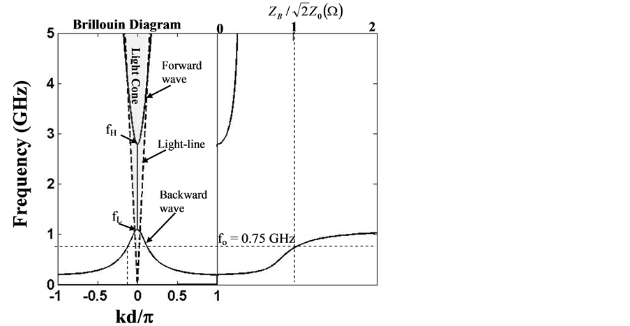
Figure 3. The dispersion diagram and the Bloch impedance plot of the metamaterial lines.

 (a) (b)
Figure 4. (a) Transmission coefficients of the metamaterial hybrid show equal power split at 0.75 GHz and harmonic rejection at 2.25 GHz. (b) Reflection and Isolation coefficients of the metamaterial hybrid.
rected phase and group velocities will be further clarified in the Section 4 by observing pulse propagation at various locations in the hybrid.
3. Gaussian Pulse Propagation
To understand the signal propagation in the hybrid, a Gaussian excitation signal is applied at the input port and the output is detected at various locations. Numerically, the response to a modulated Gaussian input pulse is given by the following integral:
 (6)
(6)
where α is the standard deviation of the pulse, ωo is the modulating frequency, and V(ω) and θ(ω) are the mag-

 (a) (b)
Figure 5. Power spectrum for the (a) traditional 180˚ hybrid and (b) the metamaterial hybrid showing the harmonic suppression at 1.5 and 2.25 GHz.

Figure 6. Plots of phase and group velocities show an oppositely directed phase and group velocities in the lowest fundamental. The phase velocity has negative polarity indicating the backward wave.
nitude and phase of the frequency response. First consider the in-phase hybrid mechanism when an input Gaussian pulse with a variance of 5ns and 0.75 GHz modulating frequency is applied at port 1. As depicted in Figure 7, the output power is evenly distributed with same phase at ports 2 and 3. An output phase shift of +90˚ with respect to the input is evident. Next consider the out-of-phase hybrid operation. In this configuration, the input Gaussian pulse is fed at the port 4 and the output responses are detected at ports 2 and 3. As given in Figure 8(a), the port 2 output is −90˚ phase shifted from the input. On the other hand, as depicted in Figure 8(b), the output at port 3 undergoes a +90˚ phase shift such that ports 2 and 3 are 180˚ out of phase with respect to each other. Note that the envelope of the Gaussian pulse propagates in the direction that is outward from the respective ports. It is the underlying phase that lags or leads depending on the port at which the excitation is provided.
4. The Contra-Directional Phase and Group Velocities
To show the contra-directed phase and group wave propagation in the ring hybrid, the progression of the Gaussian pulse travels between ports 1 and 2 is analyzed. The Gaussian pulse is excited at port 1 and the output responses are calculated at two points which are separated by two and three unit cells from the input port. Since each unit cell is 4.6mm in length (assuming zero length for the lumped elements), the total separation from the input port is 9.2 mm and 13.8 mm respectively. The points of determination of the output response are schematically shown in Figure 9. The group velocity can be readily determined taking the ratio of the distance between two points and the time require by the Gaussian envelope to travel between them:
 (7)
(7)
Consider the Gaussian pulse responses at the two designated points shown in Figure 10. Two points can be observed by comparing the plots. First, the envelope of the Gaussian pulse is indeed propagating towards the output port 2 indicating the positive group velocity. Secondly, the underlying sine wave (or the phases) travels in

Figure 7. The input pulse centered at 0.75 GHz applied at port 1 splits equally at ports 2 and 3. The output phase leads the input by a phase of 90˚.

 (a) (b)
Figure 8. The input pulse centered at 0.75 GHz applied at port 4 splits equally at ports 2 and 3. The port 2 phase lags the input by a phase of 90˚ where as the output phase at port 3 leads the intput port by 90˚.

Figure 9. Three locations at which the propagated pulse is plotted to show the contra-directed phase and group velocities and to determine the magnitude of group velocity.
the direction which is opposite to that of the envelope, a signature behavior that is observed in the backward wave regime or the regime identified by the negative phase velocity. The propagation times for the 9.2 mm and 13.8 mm distances on the hybrid are approximately equal to 0.34 ns and 0.5 ns respectively. Hence the approx

 (a) (b)
Figure 10. The time domain snapshots of Gaussian pulse as it propagates from port 1 towards port 2 at (a) after propagating through two metamaterial unit cells and (b) after propagating through three metamaterial cells.
imate group velocities from Equation (7) are given by 0.092c and 0.92c respectively which are very close to the values obtained from the dispersion relations (2) and (4) and are shown in Figure 6.
5. Conclusion
Two important properties of metamaterial-based microwave devices i.e. the harmonic suppression and the contra-directional phase and group velocities are studied. In this numerical study, a novel metamaterial 180˚ ring hybrid is designed and simulated at 0.75 GHz. The design procedure exploits the inherent filtering properties of the metamaterial transmission lines by placing a stop band in such a way that the first and second harmonics are effectively suppressed. The unique wave propagation in the hybrid is studied by exciting the input port with a band-limited Gaussian pulse of standard deviation 5 ns. The particular relation between the phase and group propagation can be observed both in the frequency-domain dispersion diagrams and the time domain simulations. In particular, the Gaussian pulse is shown to propagate at a group velocity of 0.095 c through the hybrid at the design frequency.
Cite this paper
Omar Siddiqui, (2015) Numerical Investigation of Phase and Group Propagation of Time-Domain Signals in a Novel Band-Reject Metamaterial Ring Hybrid. Journal of Computer and Communications,03,10-17. doi: 10.4236/jcc.2015.36002
References
- 1. Caloz, C. and Itoh, T. (2006) Electromagnetic Metamaterials: Transmission Line Theory and Microwave Applications. 1st Edition, John Wiley & Sons, Hoboken.
- 2. Eleftheriades, G.V. and Balmain, K.G. (2005) Negative Refraction Metamaterials: Fundamental Principles and Applications. 1st Edition, John Wiley & Sons, Hoboken.
http://dx.doi.org/10.1002/0471744751 - 3. Antoniades, M.A. and Eleftheriades, G.V. (2001) Compact, Linear, Lead/Lag Metamaterial Phase Shifters for Broadband Applications. IEEE Antennas and Wireless Propagation Letters, 2, 103-106.
http://dx.doi.org/10.1109/LAWP.2003.815280 - 4. Hu, J., Xiong, J., Ling T. and Zou, Y. (2007) Design of a Novel Wilkinson Power Splitter Based on the Left-Handed Transmission Line. Microwave and Optical Technology Letters, 49, 2975-2977.
http://onlinelibrary.wiley.com/doi/10.1002/mop.22896/abstract - 5. Qureshi, F., Antoniades, M.A. and Eleftheriades, G.V. (2005) A Compact and Low-Profile Metamaterial Ring Antenna with Vertical Polarization. IEEE Antennas and Wireless Propagation Letters, 4, 333-336.
http://dx.doi.org/10.1109/LAWP.2005.857041 - 6. Siddiqui, O. and Mohra, A. (2013) A Harmonic-Suppressed Microstrip Antenna Using a Metamaterial-Inspired Compact Shunt-Capacitor Loaded Feedline, Progress in Electromagnetics Research C, 45, 151-162.
http://dx.doi.org/10.2528/pierc13070502 - 7. Pozar, D. (2005) Microwave Engineering.3rd Edition, John Wiley & Sons, Hoboken, 352-357.
- 8. Siddiqui, O., Mojahedi, M. and Eleftheriades, G.V. (2003) Periodically Loaded Transmission Line with Effective Negative Refractive Index and Negative Group Velocity. IEEE Trans. on Antennas and Propagation, 51, 2619-2625.
http://dx.doi.org/10.1109/TAP.2003.817556 - 9. Siddiqui, O. and Eleftheriades, G.V. (2011) Study of Resonance-Cone Propagation in Truncated Hyperbolic Metamaterial Grids Using Transmission-Line Matrix Simulations. Journal of Franklin Institute, 348, 1285-1297.
http://dx.doi.org/10.1016/j.jfranklin.2010.02.005