Journal of Building Construction and Planning Research
Vol.1 No.3(2013), Article ID:36428,6 pages DOI:10.4236/jbcpr.2013.13009
Waste Shell Husks Concrete: Durability, Permeability and Mechanical Properties
![]()
Department of Environmental Science and Technology, Graduate School of Bioresources, Mie University, Tsu, Japan.
Email: zakaria@bio.mie-u.ac.jp
Copyright © 2013 Md. Zakaria Hossain. This is an open access article distributed under the Creative Commons Attribution License, which permits unrestricted use, distribution, and reproduction in any medium, provided the original work is properly cited.
Received June 2nd, 2013; revised July 26th, 2013; accepted August 5th, 2013
Keywords: Shell Husk; Recycle; Concrete; Durability; Mechanical Properties; Permeability
ABSTRACT
Shell husk is annually produced as a byproduct of shell production in Japan. According to Japanese Ministry of Forestry, Fisheries and Agriculture, the amount of the abandoned shell husk is about 151,000 tons per year. This huge amount of abandoned shell husk is not only thrown away without any commercial return but also causing pollution and environmental problems. To mitigate the pollution and environmental problems, possible utilization of abandoned shell husk is thoroughly observed in concrete construction. Overall response of the mechanical properties of concrete specimens containing different percentage of abandoned shell husk aggregates such as 0, 10%, 0, 30%, 40% and 50% in the ratio of mass is demonstrated. Results of engineering properties such as compressive strength, Young’s modulus, tensile strength, unit weight, water absorption capacity and coefficient of hydraulic conductivity are depicted. It is observed that the use of shell husk in concrete improves strength and durability performance of concrete treated in aggressive sea environments.
1. Introduction
A huge amount of abandoned Mactridae shell husk is produced in Japan every year. Mactridae, also known as trough shells or duck clams, is a family of marine bivalve clams of the order Veneroida. In Japan, the amount of the abandoned shell husk is about 151,000 tons per year according to the Japanese Ministry of Forestry, Fisheries and Agriculture. Among these, about 9627 tons/year are produced in Mie prefecture and 715 tons/year are produced in Tsu city along with 407 tons/year of mactrachinensis (mactridaes) in Tsu city. According to the information of disposal site office in Tsu city, the cost for disposing the abandoned shell husk is about 18 yen per kilogram which means that nearly 151411US$ is required for disposing abandoned shell husk in Tsu city (nearly 86188US$ is required for mactridaes) only. In addition to this, nearly 2 million US$ is required in Mie Prefecture and nearly 32 million US$ is required in Japan. These mactridaes, which are not only thrown away without any commercial return and a lot of money is being spent for its disposal but also causing pollution and environmental problems. With the rapid increase in demand for balance between natural phenomena and ecology in bio-environment, there is a significant need for continuous development of new technologies that consume these abandoned shell husks [1,2]. One idea is gaining much attention, lately, is that of the use of abandoned mactridae shell husk as recycled aggregates for the manufacture of concrete or cement-based composite materials. This solves mainly two environmental and economic aspects, such as: 1) solving the waste storage problem and 2) protection of limited natural resources of aggregates [3,4]. Both the economic and environmental benefits can be achieved by using the abandoned shell husk as recycled aggregate in concrete or in cementbased composites. Some researches on concrete or cementitious composites with other recycled aggregate produced from building destruction can be found in the technical literature [5-8]. Light weight concrete masonry with recycled wood aggregate was studied by Stahl [9]. The latest researches on the assessment of the surface resistance and permeation properties of recycled aggregates concrete are also found [10,11]. In spite of the volume of available technical information, there is a little research work on the use of abandoned shell aggregates in concrete or cement-based composites [12]. In view of the above distinct advantages for environmental conservation and protection of limited natural resources as well as economy; the present research work is undertaken to fulfill this basic need. It is expected that the outcomes of this research assist in possible utilization of abandoned shell husk as aggregate for producing a suitable concrete or cement-based composite for prospective uses in the field such as; terrace lands, roads, canals, pavements, embankments, ridge between paddy fields and other agricultural and engineering structures by controlling their physical properties such as strength and weight of these kind of composite materials. For effective utilization of concrete or cementitious composites with abandoned shell aggregates in engineering structures and building components, it is necessary to study various engineering properties such as mechanical behavior, strength, weight control and permeability of these kinds of concrete or cement based composite materials.
The purpose of the work reported in this manuscript was to investigate the overall response of the mechanical properties of concrete or cementitious composites with different percentage of abandoned mactridae shell husk as coarse aggregate such as 0, 10%, 0, 30%, 40% and 50% in the ratio of mass. Various types of tests such as compression tests, permeability tests and durability tests on concrete containing different percentage of abandoned mactridae shell husk under severe environmental conditions for a period of 28, 88, 148, 208 and 268 days were demonstrated. A comparison of the test results and pertinent discussion regarding the investigated parameters are depicted in this manuscript.
2. Materials and Methods
2.1. Collection and Grading of Abandoned Shell Husk
The abandoned mactridae shell husks were collected from the sea coast near to Mie University, Tsu city, Mie Prefecture, Japan (Figure 1). After collection, the shell husks were graded by performing sieve analysis. The fineness modulus and the maximum size of the abandoned shell husks were 4.35 and 4.76 mm, respectively. The shell size distribution curve is shown in Figure 2 and the physical properties are given in Table 1.
2.2. Specimen Preparation
The requisite amount of shells, sand and cement was drymixed in a pan, and then the requisite quantity of water was added gradually while the mix was continuously stirred (Figure 3).
Cylindrical specimens were made in the metal moulds with open tops. The moulds were made in such a way that the side walls and the base were detachable so that the mould could be easily separated from the specimens after its initial setting. The percentage of recycled shell

Figure 1. Abandoned Mactridaes hell husksin Tsu city, Mie Prefecture, Japan.

Figure 2. Shell size distribution curve.

Table 1. Physical properties of shell husk concrete.

Figure 3. Dry-mixing of shell husks with sand-cement.
aggregates were marked on the elements, and the date of casting were recorded. The contact surfaces of the mould to the mortar were greased before casting the specimens to ease the demolding process.
Ordinary Portland cement and river sand passing through a No. 8 (2.38 mm) sieve, which has a fineness modulus of 2.33, were used for casting. For all the specimens, the water to cement ratio and cement to sand ratio both were 0.5 by weight. The specimens were airdried for 24 hours for initial setting (Figure 4) and then immersed in water for curing (Figure 5). The specimens were removed from water after 28 days and were air-dried for 2 days in room temperature of about 25˚C and relative humidity of about 50%; then the tests were performed.
2.3. Testing under Compression
All the specimens were tested with a 1962 kN capacity hydraulic testing apparatus (Figure 6). The maximum capacity of the machine was adjustable to reduce scale and was set to 196.2 kN. The readings were taken initially at an interval of 9.81 kN and subsequently at 4.905 kN. The displacements were measured with a dial gauge having a least count of 0.01 mm. A careful attention was taken to eliminate the effect of end restraint of the test specimens. It was attempted to eliminate the initial slackness of the machine components and the contact points by exercising the test specimens under a small load before applying final load cycle to failure. The load application was continued until the deformation became excessive. Most of elements failed with cracking noise and some elements showed spalling off the mortar cover over the aggregates associated with a rapid drop in load.
2.4. Testing for Hydraulic Conductivity
Hydraulic conductivity testing apparatus used in this research is shown in Figure 7. The hydraulic conductivity tests were conducted by the constant head permeability test method according to JIS 1218. The specimens for the permeability tests were prepared in the steel mold of 10.0 cm in diameter and 20.0 cm in height. The specimen was cut to height 6.0 cm with permeable surfaces at top and bottom. Epoxy resin was used to block the clearance between the mold-wall and the specimen periphery so that water can pass within the specimen only. The mold with specimen was placed on a stand to ease in collecting the outlet water by a graduated cylinder. The water pressures gauge was set at the upper plate of the specimens to confirm the constant water pressure on the specimen. Before applying the pressure from the gas cylinder, the water from the water tank was poured to the pressure chamber by adjusting the water control valve. The water of pressurized chamber was then poured on the specimen. During pouring the water into the mold, the air inside the mold on the top of the specimen was released by the air

Figure 4. Casting of shell husk concrete.

Figure 5. Curing of shell husk concrete.

Figure 6. Compressive test apparatus.

Figure 7. Hydraulic conductivity test apparatus.
release valve. The front face of the specimen was continuously connected to the pressurized water chamber during the test. Therefore, the top surface of the water in the mold was subjected to a constant pressure of 3.0 MPa (gauge pressure). The amount of water flowing through the specimen was measured by the collected water in the graduated cylinder. Before recording the readings, percolation was allowed for some time to ensure a high degree of saturation and uniformity of the test results.
2.5. Tensile Strengths and Modulus of Elasticity
The test method for splitting tensile strength of cylindrical concrete specimens was followed according ASTM C496/C496M-11 standards. The size of specimen was length 20 cm and diameter 10 cm.
3. Results and Discussion
3.1. Results
The average values of 3 specimens of the cementitious composites containing 0, 10%, 20%, 30%, 40% and 50% recycled shell aggregate is given in Table 2. It is evident that the compressive strength, modulus of elasticity and tensile strength of the cementitious composites decreased with the increase in shell content. This table also shows that the unit weight of the composite decreased significantly with the increase in the shell content which can be taken as a controlling parameter along with strength. The structure where strength is not a main factor but it needs to be lighter weight, such as, partition wall; in that case, cementitious composites with higher percentage of shell content may be used. On the other hand, the structure where the weight is not a main factor but it needs to be strong and durable, such as, roads, embankment, pave-

Table 2. Properties of shell husk concrete.
ments and earth slope protection; in that case, cementitious composites with lower percentage of shell content may be used. Water absorption tests and hydraulic conductivity tests results show that the amount of water absorption and coefficient hydraulic conductivity (k) increased with the increase in the amount of shell content. The higher rate of water absorption and k was occurred due to the higher pore space in concrete. This indicates the effectiveness of the higher amount of shell contents in concrete.
The durability tests of concrete containing 50% shell treated in severe environment such as in saline water (sea-water) for a period 28, 88, 148, 208 and 268 days are given in Figure 8. Before placing the specimens in sea water, basic curing for a period of 28 days in fresh water at the laboratory was done for all the specimens. This figure shows the average compressive strengths of 3 specimens in each group. Notice a significant increase in strengths of concrete due to the presence of shell husk aggregate indicating the effectiveness of shell husks in concrete treated in saline water (sea-water).
3.2. Interrelationships of Mechanical Properties
By analyzing experimental data, interrelationships among the physical properties of concrete containing different amount of shell husk such as relationships of the compressive strengths and the modulus of elasticity, relationships of the tensile and the compressive strengths are given as follows.
3.3. Relationships of the Young’s Modulus and the Compressive Strength
According to the test method of ASTM C469, the laboratory tests were carried out and the Young’s modulus was calculated from the stress strain relationships by avoiding the nonlinearity at the initial and final loading conditions using Equation (4).
 (1)
(1)
where E is the modulus of elasticity, s1 is the stress corresponding to strain of 0.00005, s2 is the stress corre-

Figure 8. Durability tests in saline water.
sponding to 40% of ultimate strength and e2 is the strain produced by stress s2. The following relationships between the compressive strengths and the Young’s modulus are obtained based on the experimental data:
 (2)
(2)
where E is Young’s modulus of composite in MPa,  is the compressive strength of composite in MPa, a is the constant which has values of 2333, 1993, 1790, 1601, 1566 and 1530 for concrete of control, 10%, 20%, 30%, 40% and 50% shell husk, respectively. It is noted here that the empirical relationship between the compressive strength and the Young’s modulus of recycled aggregate concrete by the ACI code is given as follows:
 (3)
(3)
where g is the unit weight of concrete in pound per cubic feet. This Equation is the well-known form for normal weight concrete with g value of 145 pound per cubic feet, which is written as follows:.
 (4)
(4)
The Equation 4 by the ACI code can be rewritten in SI unit as follows:
 (5)
(5)
where, Young’s modulus (E) and compressive strength ( ) are in MPa. The a values of Equation 2 obtained in this research are smaller than the coefficient of Equation 5 given by ACI indicates the proposed Equation provides conservative estimation of the Young’s modulus of concrete containing shell husks. This type of behavior was observed in the technical literature in case of concrete containing different recycled aggregate [11-13].
3.4. Relationships of the Splitting Tensile Strength and the Compressive Strength
By performing the analyses of the experimental data, the relationship between the splitting tensile strength and the compressive strengths can be written as follows:
 (6)
(6)
where,  is the splitting tensile strength in MPa,
  is compressive strength in MPa and b is an empirical constant which takes the values of 0.56, 0.57, 0.60, 0.63, 0.67 and 0.69 for concrete of control, 10%, 20%, 30%, 40% and 50% shell husk, respectively. It should be pointed out here that the ACI code used for estimating the splitting tensile strength is given follows:
 (7)
(7)
where,  is the splitting tensile strength in MPa and
  is compressive strength in MPa. It is evident that the results agree well with the ACI equation of recycled aggregates concrete of plain mortar.
3.5. Discussion
The scanning electron microscope (SEM) analysis was done on the shell husks concrete and SEM image is given in Figure 9. As can be seen, the SEM image has cavity or pore space inside the shell husk concrete. This pore space facilitate the water absorption capacity of shell husk concrete which further reinforced the results given in Table 2.
The initial and final nonlinearity was avoided from the stress strain relationships. Although there was a limitation of test setup and the displacement measuring gage was set at machine component, however, the axial strain obtained during testing was similar to that of change in height or length of the specimen and the results obtained are promising for abandoned shell husk concrete. The tensile splitting tests were carried out on the cylindrical specimens. The test method for splitting tensile strength of cylindrical concrete specimens was followed according ASTM C496/C496M-11 standards. The size of specimen was length 20 cm and diameter 10 cm. The stress displacement curve is shown in Figure 10.
After eliminating the initial and final nonlinearity, the linear portion shown Figure 10 is used to calculate to modulus of elasticity given in Table 2. The stress-strain curves for 10% shell husk concrete are reported. The stress-strain curves for other cases are similar trend and therefore, these are not repeated here. It is noted here that the slump tests were performed for the workability of shell husk mortar mix. For all the mixes, the value of slump was found as 70 - 95 mm without any admixture. It is interesting to note that the high water absorption of shell husk concrete reduces the rain water retention on the surface of the structure made of shell husk concrete. Therefore it reduces the risk of flood water during rainfall. This is beneficial for earth slope protection work to reduce pore water pressure inside the slope and thereby increases the stability of slope.
4. Conclusion
The possible utilization of abandoned shell husks in con-

Figure 9. Scanning Electronic Microscopic (SEM) image of shell husk concrete.
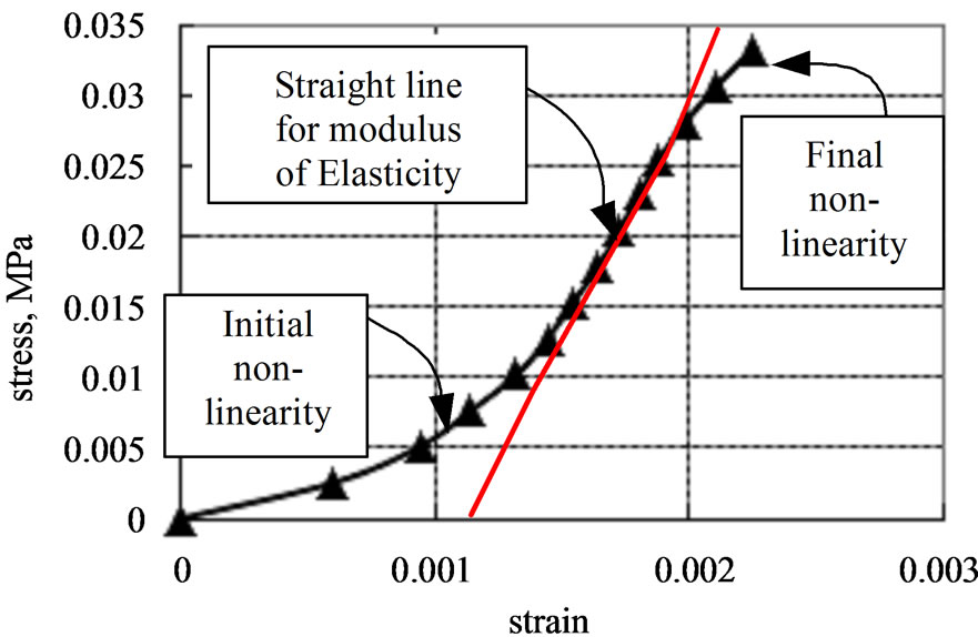
Figure 10. Stress-stress curve and linearity for modulus of elasticity.
crete construction is studied in this paper. Engineering properties such as compressive strength, Young’s modulus, tensile strength, unit weight, water absorption capacity and coefficient of hydraulic conductivity results agree well with the ACI results. In designing light weight concrete structures such as partition wall, slope surface protection, ridge between paddy fields, roads and embankments slopes and sea-shore protection structures where strength is not a great factor but the water absorption properties are advantageous, concrete with shell aggregates may be used.
5. Acknowledgements
The present study is partly supported by the Research Grant No. 22580271 with funds from Grants-in-Aid for Scientific Research, Japan. The author gratefully acknowledges these supports. Any opinions, findings, and conclusions expressed in this paper are those of the authors and do not necessarily reflect the views of the sponsor.
REFERENCES
- I. Wang, S. Takamura, M. Nakamura and Y. Tsukinaga, “A Study on the Ratio and Composition of the Porous Concrete Containing Shells,” Transactions of Cement and Concrete, Vol. 57, 2003, pp. 572-577 (In Japanese).
- M. Delwar, M. Fahmy and R. Taha, “Use of Reclaimed Asphalt Pavements as an Aggregate in Portland Cement Concrete,” ACI Materials Journal, Vol. 94, No. 3, 1997, pp. 251-256.
- Y. Kansai, “Demolition and Reuse of Concrete Masonry,” Proceedings RILEM Symposium, Tokyo, Chapman and Hall, 7-11 November 1988, p. 774.
- T. C. Hansen, “Recycled Aggregates and Recycled-Aggregates Concrete, State-of-the-Art Report Developments 1945-1985,” RILEM Technical Committee 37-DRC, Material Structures, Vol. 19, No. 11, 1986, pp. 20-46.
- K. A. Rim, A. Ledhem, O. Douzane, R. M. Dheilly and M. Queneudec, “Influence of the Proportion of Wood on the Thermal and Mechanical Performances of Clay-Cement-Wood Composites,” Cement and Concrete Composites, Vol. 21, No. 4, 1999, pp. 269-276. doi:10.1016/S0958-9465(99)00008-6
- A. Ajdukiewicz and A. Kliszczewicz, “Influence of Recycled Aggregates on the Mechanical Properties of HS/ HPC,” Cement and Concrete Composites, Vol. 24, No. 2, 2002, pp. 269-279. doi:10.1016/S0958-9465(01)00012-9
- N. Banthia and C. Chan, “Use of Recycled Aggregate in plain and Fiber Reinforced Shot Crete,” Concrete International: Design and Construction, American Concrete Institute, Vol. 22, No. 6, 2000, pp. 41-46.
- K. K. Sagoe-crentsil, T. Brown and A. H. Taylor, “Performance of Concrete Made with Commercially Produced Coarse Recycled Concrete Aggregate,” Cement and Concrete Research, Vol. 31, No. 5, 2001, pp. 707-712. doi:10.1016/S0008-8846(00)00476-2
- M. Z. Hossain and S. Inoue, “Finite Element Analysis of Thin Panels Reinforced with a Square Mesh,” Journal of Ferrocement, Vol. 32, No. 2, 2002, pp. 109-125.
- D. C. Stahl, G. Skoraczewski and B. Stempski, “Light Weight Concrete Masonry with Recycled Wood Aggregate,” Journal of Materials in Civil Engineering, Vol. 14, No. 2, 2002, pp. 116-121. doi:10.1061/(ASCE)0899-1561(2002)14:2(116)
- T. Yamauchi, H. Sahara and K. Kudo, “On the Use of Hotate Shells as Concrete Aggregates,” Proceedings of the 60th Technical Conference of Civil Engineering, Tokyo, 7-9 September 2005, pp. 435-437 (in Japanese).
- S. T. Frondistou-Yannas, “Waste Concrete as Aggregate for New Concrete,” ACI Journal, Vol. 74, No. 8, 1977, pp. 373-376.
- T. C. Hansen and E. Boegh, “Elasticity and Drying Shrinkage of Recycled Aggregate Concrete,” ACI Journal, Vol. 82, No. 5, 1985, pp. 648-652.