Journal of Biomedical Science and Engineering
Vol. 5 No. 12A (2012) , Article ID: 26277 , 8 pages DOI:10.4236/jbise.2012.512A112
The hemodynamic study for growth factor evaluation of rupture cerebral aneurysm followed up for five years
![]()
1Department of Micro-Nano System Mechatronics, Nagoya University, Nagoya, Japan
2Department of Neurosurgery, Fujita Health University, Toyoake, Japan
3Department of Mechanical Engineering, Nagoya University, Nagoya, Japan
Email: kojima2@robo.mein.nagoya-u.ac.jp
Received 27 October 2012; revised 26 November 2012; accepted 11 December 2012
Keywords: Simulation; Aneurysm; PIV
ABSTRACT
Computer-based simulations are essential for clarifying the hemodynamics of brain aneurysms. Since cerebrovascular disease is often fatal, it is strongly desirable to predict its progression. While previous studies have clarified the initiation mechanism of aneurysms, their growth mechanism remains unclear. Consequently, it is difficult to develop a diagnostic system for predicting aneurysm rupture. This study seeks to clarify the mechanism of aneurysm growth by identifying significant hydrodynamic factors. We focus on a single ruptured aneurysm that was followed up for five years. Computer simulations and fluid dynamic experiments with silicone vessel models were performed. To confirm the reliability of data in the computer simulations, we conducted particle image velocimetry measurements in steady flow. We then performed computer simulations for pulsatile conditions to determine an effective index for aneurysm growth. We obtained good agreement between the trends in the obtained computer simulation and experimental data. Numerical simulations for pulsatile flow in three models revealed that aneurysms grew in regions having a low wall shear stress, a low aneurysm formation indicator, and a high oscillatory shear index.
1. INTRODUCTION
A World Health Organization report on the top 10 causes of death ranks stroke and other cerebrovascular diseases second with 6.15 million people dying worldwide from such diseases every year. Intracranial aneurysm is a cerebral vascular disease characterized by weakening and bulging of a portion of an artery. It has a high fatality rate and often induces permanent damage. Therefore, an intelligent diagnostic system is desired that can predict cerebral aneurysm rupture. Such a system will assist doctors in providing the initial diagnosis and planning for surgery. However, the aneurysm rupture mechanism has yet to be clarified due to the very complex interaction between endothelial cell functions and hemodynamic stimulus. Moreover, artery parameters (e.g., the wall shear stress, the blood pressure, and the blood velocity) are difficult to measure in vivo because cerebral vessels are narrow and complicated. However, with advances in computing, various parameters of cerebral vessels can be accurately estimated by numerical simulations. In recent years, computational fluid dynamics studies have been performed using computed tomography and magnetic resonance angiography (MRA) data to clarify the mechanism of cerebral vascular disease. The flow dynamics in cerebral vessels has been studied by using medical image data and experimental models. Clinical studies have revealed that the main factors that induce aneurysm rupture are blood pressure and wall shear stress. Moreover, a low flow speed with oscillating flow, which disrupts an array of endothelial cells is thought to induce aneurysm initiation [1]. In an in vitro study, Tateshima et al. [2,3] created a rigid silicone model of a middle cerebral artery aneurysm from computed tomography data. They compared two silicone models based on data from two successive years. They found that the wall shear stress is lower at the tip of the aneurysm in the second year model than in the first year model. However, they found no clear distinction between the two models. Recent computer simulation studies have proposed various indices for detecting aneurysm initiation. Ku et al. [4] proposed the oscillatory shear index (OSI), which is considered to be as a significant factor for aneurysm rupture. The aneurysm formation indicator (AFI) [5], the gradient oscillatory number (GON) [6], and the wall shear stress gradient (WSSG) [7] have also been proposed as important factors for aneurysm initiation. However, no studies have investigated the growth process that leads to rupture of a cerebral aneurysm by performing long-term follow-up. In addition, previous studies have not sufficiently validated computer simulation data. Consequently, the reliability of indices cannot be confirmed. To remedy this situation, this study focuses on rupture of a single aneurysm followed up for five years.
2. MATERIALS AND METHODS
2.1. Sequential Vascular Models over Five Years
This study investigates a ruptured aneurysm in the ophthalmic artery by performing five-year follow-up. Figure 1 shows nine time-sequential vascular models that were constructed from three-dimensional (3D) MRA Digital Imaging and Communications in Medicine images. Filtering and segmentation algorithms were applied to remove noise from data of the vascular network. Vascular models were then smoothed and truncated perpendicularly at the inflow and outflow regions.
2.2. Computer Fluid Dynamics
In the calculation scheme, we used a 3D segregated solver and a second-order implicit formulation in time. We assumed blood to be an incompressible Newtonian fluid and modeled its flow using the 3D unsteady NavierStokes equations. Vessel walls were assumed to be elastic (elastic modulus: 2.0 MPa; Poisson ratio: 0.45) and non-slip boundary conditions were applied at the walls. The governing equations for fluid are the continuity equation and the Navier-Stokes equations for incompressible flow.
 (1)
(1)
 (2)
(2)
Here, ρ is the density and u is the velocity. In this calculation, we consider flow in a cerebral aneurysm to be laminar. To confirm the reproducibility of fluidic phenomena in a three-times scaled up model, we considered two dimensionless numbers. One of these numbers is the Reynolds number, which is given
 (3)
(3)
where V is the velocity [m/s], D is the vessel inlet diameter [m], and ν = μ/ρ is the kinematic viscosity [m2/s].
2.3. Boundary Conditions
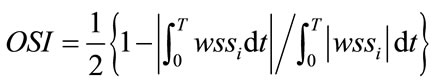
Pulsed blood flow at the blood vessel inlet was measured by MRA from actual seven patients. The data was obtained as the flow volume for the same ICA cross section using MRA with a resolution of 20 Hz. Because pulse period differs between patients, we normalized it at 1 Hz and averaged seven patients’ data. The Reynolds number was 223 in the diastolic phase and 571 in the systolic phase during a pulse period. First, we performed numerical simulations and PIV measurements under the same static conditions to confirm the accuracy of the simulations. Figure 2(a) shows the static conditions. We set the Reynolds number to 233 and the pressure to 83 mmHg for 1 second during PIV experiments and numerical simulations. These values represent the diastolic phase and minimum Reynolds number in the pulse wave. Figure 2(b) shows the waveform obtained from these patients. Numerical simulations for dynamic flow were then performed to mimic blood flow in humans. We set the Reynolds number 223 - 571 to reproduct the dynamic similarity of pulsatile waveform of human. The OSI [4] was calculated from the instantaneous value of the wall shear stress wssi over the period T using.
 (4)
(4)
The OSI value is evaluation function and indicates how much the wall shear stress is oscillating over the period.

Figure 1. 9 sequential vascular models followed up for five years from March 2006 to February 2011.

Figure 2. Waveform; (a) static condition; (b) pulsatile condition. The AFI [5] was obtained from the average wall shear stress wssav using.
The AFI [5] was obtained from the average wall shear stress wssav using
 (5)
(5)
The value of AFI also means how much the instantaneous vector of the wall shear stress wssi is reversed for the average wall shear stress wssav.
2.4. Particle Image Velocimetry
To verify the accuracy of the computer fluid dynamics data, experiments were conducted in an in vitro environment using a silicone blood vessel model in membrane configuration; it was constructed using the technique proposed by Ikeda et al. [8]. The membrane model was built from 3D geometry data obtained by scanning the cerebral arteries of a patient. It reconstructs human arteries with an accuracy of 13 μm. In this model, the arteries have an elastic modulus of 2.0 MPa and a friction coefficient of 0.042. This silicone phantom model was scaled up by a factor of three. The thickness of the blood vessel membrane was taken to be 500 μm. The three models used in the experiments were obtained by 3D MRA scans performed on 16 Feb. 2006, 30 Aug. 2008, and 22 Oct. 2010. Figure 3(a) shows the silicone model developed from the MRA scan performed on 30 Aug. 2008. We confirmed that red ink flows through the silicone model as shown in Figure 3(b).
2.5. Experiment Environment
Figure 4 shows a schematic diagram of the experimental environment. This system includes an imaging system that has a high-speed camera (Ditect, HAS-500) and a capture board (Ditect, HAS-GLINK). This camera takes video images with 1024 × 512 pixels that are stored in dynamic memory at a rate of 500 frames per second. A

Figure 3. (a) Membranous silicone phantom model on 30 Aug. 2008; (b) Flow of red color ink in this model.

Figure 4. Schematic image of whole system of experiment.
flow meter (Keyence, Japan, FD-SS2A) was inserted in the middle of the flow circuit and it was used to maintain the flow conditions. The flow volume was measured at a resolution of 1 ml/min. To visualize the flow in the silicone model, we used fluorescent micro particles as tracer particles in the PIV measurements. Using these particles and a long-pass filter (550 nm), we could obtain clear images as a result of eliminating noise originating from light reflected from the boundary of the silicone model and bubbles in the working fluid. The particle diameter is 15 μm and the absorption and emission wavelengths are respectively 530 and 580 nm. The light source was a Nd:YAG laser (wavelength: 532 nm; Dan tec Dynamics, RayPower 2000). In addition, we built a heartbeat flow simulator that consisted of a 6-lpm magnetic drive pump whose pulse width could be varied using preprogrammed pressure waveforms. Pressure feedback control was realized using a 5-PSI analog pressure sensor (Honeywell); the minimum and maximum pressures were controlled. The pump used a PIC18F1320 at 20 MHz as a controller. The circulating solution in the simulator can be heated to a maximum temperature of 40˚C. In this study, we used this pump to generate steady flow. The Reynolds number and the pressure of the flow were set to 233 and 80 mmHg, respectively. Figure 5 shows the coordinate system for defining the measurement cross section. We compared experimental and simulation data at the same central cross section of the aneurysm.
3. RESULTS
To confirm the accuracy of the simulation data by comparing it with the experimental data, Figure 6 shows the results of the PIV measurements and numerical simulations for the three models (Feb. 2006, Aug. 2008, and Oct. 2010). The PIV results are shown in 06-a, 06-b, 08-a, 08-b, 10-a, and 10-b, while the computer simulation results are shown in 06-c, 06-d, 08-c, 08-d, 10-c, and 10-d. Due to the growth of the aneurysm, the location of the measurement cross section varies between the three models: for the 2006 model, the measurement position is x = 8 mm and z = 8 mm, whereas it is x = 9 mm and z = 9 mm for the 2008 and 2010 models. These results reveal vortex flow in the aneurysm. Moreover, the center point of the vortex varied with the geometry. The flow velocity in the aneurysm was higher in the 2008 model than the 2006 and 2010 models. The blood flow in the aneurysm clearly varies dynamically with aneurysm growth. In the PIV measurements, the location

Figure 5. Coordinate system for positioning cross section of measurement.

Figure 6. Visualized results of PIV experiment and numerical simulation of 3 models. 06: Feb. 2006 model, 08: Aug. 2008 model, 10: Oct. 2010 model. PIV Experiment: 06 - a: Velocity vector at the cross section of x = 8 mm, 08 - a, 10 - a: Velocity vector at x = 9 mm, 06 - b: Velocity vector at z = 8 mm, 08 - b, 10 - b: at the section of z = 9 mm. Numerical simulation: 06 - a: Velocity vector at the cross section of x = 8 mm, 08 - a, 10 - a: Velocity vector at x = 9 mm, 06 - b: Velocity vector at z = 8 mm, 08 - b, 10 - b: at the section of z = 9 mm.
of the cross section has a margin of error since the laser sheet is approximately 1.5 mm thick. Consequently, it was difficult to obtain a perfect match between the experimental and computer simulation data. However, the experimental and computer simulation data exhibit similar qualitative trends. Figure 7 shows the numerical simulation results for the three models for pulsatile flow in the systolic phase. The systolic phase is the phase in which the flow into the aneurysm is a maximum. The period differs between the three models: the systolic phase lasts for 0.230, 0.185, and 0.203 s in the 2006, 2008, and 2010 models, respectively. 06-A, 08-A, and 10-A in Figure 7 show the results for the wall shear stress. 06-B, 08-B, and 10 B in Figure 7 are the calculated values of the AFI. 06-C, 08-C, and 10-C are the results for the OSI. The results of 06-A, 08-A, and 10-A reveal that there is a low wall shear stress near the aneurysm (indicated by the white arrows in Figure 7). Moreover, the aneurysm clearly grows from this region with a low wall shear stress. A similar tendency is observed in 06-B, 08-B, and 10-B in Figure 7. A low AFI indicates a region of reverse flow. The AFI results indicate that the aneurysm grows from regions of reverse flow. Moreover, for 06-C, 08-C, and 10-C in Figure 7, the high OSI region coincides with the low WSS and low AFI region. These results indicate that the aneurysm grows at the region with a low WSS, a low AFI, and a high OSI.
4. DISCUSSION
This is the first study analyzing the growth factor of aneurysm focusing on flow dynamics by using long term followed up aneurysm models. Moreover, this study seeks to find an important index for aneurysm growth with the aim of developing an intelligent diagnosis system that can predict the rupture of cerebral aneurysms.
Previous study [2,3] also tried to compare the two growing aneurysm models during two successive years. However, there was no clear distinction between two models and it was still unclear what is critical factors for growing aneurysm. Therefore, this study has used three models during the process to the rupture of aneurysms over five years. We could find clear difference of shape of aneurysms and flow dynamics between three models. The results indicate that aneurysms grow in regions with a low WSS, a low AFI, and a high OSI. Previous studies [9-11] of aneurysms have demonstrated that blood pressure and wall shear stress affect aneurysm initiation. In addition, the AFI and OSI are significant in aneurysm

Figure 7. Visualized results of numerical simulation of 3 models in the condition of pulsatile flow at the phase of maximum flow. Results of wall shear stress are shown in 06 - A, 08 - A, 10 - A and AFI are in 06 - B, 08 - B, 10 - B. OSI are in 06 - C, 08 - C, 10 - C.
initiation. In this study, we found that a low WSS and reverse and oscillating flows promote aneurysm growth. We also confirmed the results of previous studies that blood pressure affects aneurysm growth. However, we did not find any relationship between blood pressure and the growth region as shown in Figure 8. Although pressure difference could be fond on the surface of each aneurysm, it seems that there may be no relationship between the blood pressure and growth area of aneurysm from this result. Figure 9 shows the variations in the volume and surface area of the aneurysm over a five-year period. It shows that the aneurysm grew rapidly after May 2009. In Feb. 2011, the aneurysm volume and surface area decreased due to rupture. This result implies that the rates of change of the surface area and volume of an aneurysm can be used as indices for a prediction system. Figure 10 shows the positional relationship of the geometric parameters. Figure 11 shows the geometric values of the 2006, 2008, 2010, and 2011 models. Neck length is inflow zone of aneurysm. Here, the longitudinal diameter is defined as the distance from the neck to the tip of the aneurysm, while the lateral diameter is the maximum width of the aneurysm.
 (6)
(6)
Surveys of clinical data [12,13] indicate that an aspect ratio of over 1.6 is a rupture risk indicator. In Figure 11, the rates of change of the longitudinal diameter and the aspect ratio are considerably higher than those of the neck length and the lateral diameter. This result implies that the aspect ratio is also an important index for predicting rupture. However, the membranes of the modes are considered to have uniform thicknesses in this study.
The thickness of an actual aneurysm in the human body varies between the neck and the tip. In addition, the aneurysm tip is thought to be thinner than the main artery [14,15]. Therefore, we intend to account for the effect of the membrane thickness in a future study. A more reliable intelligent diagnosis system can be produced by gaining some insight into the relationship between the blood vessel thickness and the rupture model of an aneurysm.
The current study has several limitations. It used New-

Figure 8. Results of pressure distribution for 3 models.

Figure 9. Change of surface area and volume of aneurysm over five years.

Figure 10. Geometric data of each model.

Figure 11. Geometric value of each aneurysm model in 2006, 2008, 2010 and 2011.
tonian blood properties, which may cause some parameters to be overestimated. Furthermore, it was performed using a single patient vascular model at a particular location and hence the results may not be generalizable. However, we hope that the simulation results will contribute to the development of an intelligent diagnosis system for predicting the rupture of cerebral aneurysms.
5. CONCLUSION
Fluid dynamics experiments with silicone vessel models and computer simulations were performed. To validate the computer simulation data, we conducted PIV measurements of steady flow. Computer simulations for pulsatile conditions were then performed to find an important index for aneurysm growth. We qualitatively compared the computer simulation and experiment data and found that they exhibited similar trends. Analysis of simulation data for pulsatile flow for the three models revealed that the aneurysm grew from a region with a low wall shear stress, a low AFI, and a high OSI.
REFERENCES
- Malek, A.M., Alper, S.L. and Izumo, S. (1999) Hemodynamic shear stress and its role in atherosclerosis. Journal of the American Medical Association, 282, 235-242. doi:10.1001/jama.282.21.2035
- Tateshima, S., Tanishita, K., Omura, H., Villablanca, J.P. and Vinuela, F. (2007) Intra-aneurysmal hemodynamics during the growth of an unruptured aneurysm: In vitro study using longitudinal CT angiogram database. American Journal of Neuroradiology, 28, 622-627.
- Tateshima, S., Tanishita, K., Omura, H., Sayre, J., Villablanca, J.P., Martin, N. and Vinuela, F. (2008) Intra-aneurysmal hemodynamics in a large middle cerebral artery aneurysm with wall atherosclerosis. Surgical Neurology, 70, 454-462. doi:10.1016/j.surneu.2008.03.035
- Ku, D.N., Giddens, D.P., Zarins, C.K. and Glagov, S. (1985) Pulsatile flow and atherosclerosis in the human carotid bifurcation. Positive correlation between plaque location and low oscillating shear stress. Arteriosclerosis, Thrombosis, and Vascular Biology, 5, 293-302. doi:10.1161/01.ATV.5.3.293
- Mantha, A., Karmonik, C., Benndorf, G., Strother, C. and Metcalfe, R. (2006) Hemodynamics in a cerebral artery before and after the formation of an aneurysm. American Journal of Neuroradiology, 27, 1113-1118.
- Shimogonya, Y., Ishikawa, T., Imai, Y., Matsuki, N. and Yamaguchi, T. (2009) Can temporal fluctuation in spatial wall shear stress gradient initiate a cerebral aneurysm? A proposed novel hemodynamic index, the gradient oscillatory number (GON). Journal of Biomechanics, 42, 550-554. doi:10.1016/j.jbiomech.2008.10.006
- Meng, H., Wang, Z., Hoi, Y., Gao, L., Metaxa, E., Swartz, D.D. and Kolega, J. (2007) Complex hemodynamics at the apex of an arterial bifurcation induces vascular remodeling resembling cerebral aneurysm initiation. Stroke, 38, 1924-1931. doi:10.1161/STROKEAHA.106.481234
- Ikeda, S., Arai, F., Fukuda, T., Negoro, M. andIrie, K. (2005) An in vitro patient specific biological model of the cerebral artery reproduced with a membranous configuretion for simulating endovascular intervention. Journal of Robotics and Mechatronics,17, 327-333.
- Gonzalez, C.F., Cho, Y.I., Ortega, H.V. and Moret, J. (1992) Intracranialaneurysms: Flow analysis of their origin and progression. American Journal of Neuroradiology, 13, 181-188.
- Rossitti, S., (1998) Shear stress in cerebral arteries carrying saccular aneurysms. A preliminary study. Acta Radiologica, 39, 711-717. doi:10.3109/02841859809175503
- Jamous, M.A., Nagahiro, S., Kitazato, K.T., Satoh, K. and Satomi, J. (2005) Vascular corrosion casts mirroring early morphological changes that lead to the formation of saccular cerebral aneurysm: An experimental study. Journal of Neurosurgery, 102, 532-535. doi:10.3171/jns.2005.102.3.0532
- Ujiie, H., Tachibana, H., Hiramatsu, O., Hazel, A.L., Matsumoto, T., Ogasawara, Y., Nakajima, H., Hori, T., Takakura, K. and Kajiya, F. (1999) Effects of size and shape (aspect ratio) on the hemodynamics of saccular aneurysms: A possible index for surgical treatment of intracranial aneurysms. Journal of Neurosurgery, 45, 119-127. doi:10.1097/00006123-199907000-00028
- Ujiie, H., Tamano, Y., Sasaki, K. and Hori, T. (2001) Is the aspect ratio a reliable index for predicting the rupture of a saccular aneurysm? Neurosurgery, 48, 495-503. doi:10.1097/00006123-200103000-00007
- Suzuki, J. and Ohara, H. (1978) Clinicopathological study of cerebral aneurysms: Origin, rupture, repair and growth. Journal of Neurosurgery, 48, 505-524.
- Abruzzo, T., Shengelaia, G.G., Dawson, R.C., Owens D.S., Cawley, C.M. and Gravanis, M.B. (1998) Histologic and morphologic comparison of experimental aneurysms with human intracranial aneurysm. American Journal of Neuroradiology, 19, 1309-1314. doi:10.3171/jns.1978.48.4.0505