World Journal of Engineering and Technology
Vol.03 No.04(2015), Article ID:61617,20 pages
10.4236/wjet.2015.34029
Assessment of Seagoing Ships Longitudinal Strength in the Context of International Rules, Important Factor for Safe Operation
Dumitru Lupascu1, Ionel Chirica2*
1RNR CERT SA, Bucharest, Romania
2University Dunarea de Jos of Galati, Galati, Romania

Copyright © 2015 by authors and Scientific Research Publishing Inc.
This work is licensed under the Creative Commons Attribution International License (CC BY).


Received 19 August 2015; accepted 27 November 2015; published 30 November 2015

ABSTRACT
The paper is focused on the ship hull safety problems related to the longitudinal strength of the ship during design, construction and service in context of International Goal-Based Ship Construction Standards carried out by International Maritime Organization (IMO). The study underscores the importance of ship longitudinal strength for prevention of theirs losses, mentioning the most important measures taken by IMO for improvement of ship safety. In the work, a critical analysis of the methodology of the International Association of Classification Societies (IACS) for calculation of sectional efforts induced by waves in ship’s hull is described. Finally, a calculation base proposal for improvement the efforts on quasi-static layout of the ship on wave is performed.
Keywords:
International Goal-Based Ship Construction Standards, Ship Construction Safety, Longitudinal Strength, Fatigue Strength, Sectional Efforts

1. Introduction
Safety construction of seagoing ships is one of the most important goals of International Maritime Organization (IMO) to reduce material and human life losses and to decrease environment pollution due to international maritime transport.
In order to accomplish this goal, IMO has adopted the International Goal-Based Ship Construction Standards (GBS), organized on 5 tiers as indicated in [1] :
Tier I―Goals. High-level objectives have to be met;
Tier II―Functional requirements. Criteria to be satisfied in order to conform to the goals;
Tier III―Verification of conformity. Procedures for verifying that the rules and regulations for ship design and construction conform to the goals and functional requirements [2] ;
Tier IV―Rules and regulations for ship design and construction. Detailed requirements developed by IMO, national administrations and/or recognized organizations and applied by national administrations and/or recognized organizations acting on their behalf to the design and construction of a ship in order to conform to the goals and functional requirements;
Tier V―Industry practices and standards. Industry standards, codes of practice and safety and quality systems for shipbuilding, ship operation, maintenance, training, manning, etc., which may be incorporated into, or referenced in, the rules and regulations for the design and construction of a ship.
A lower level of safety construction may determine material losses and failures, human life losses or ecological disasters.
Hereby, for example, in the period 1966-1985, annually over 300 ships [3] have been lost. After this period, the number of losses starts to decrease continually at the same time with improving technical regulations, mainly through bringing into force the new unified requirements for longitudinal strength by International Association of Classification Societies (IACS), of new IMO intact stability requirements from SOLAS Convention, through adoption of MARPOL Convention and strengthen of Port State Control (PSC), determining that after 2000 the number of ships lost will annually drop under 170, which means under 0.2%, and after 2010 less than 120 [4] .
Among lost ships, a significant share was confined by bulk carriers and oil tankers, some of them braking down through collapse of longitudinal stiffeners of the hull and breaking down into two parts, as could be seen in Figures 1-3.
Coordinated studies showed that losses caused by hull breaking down depended probabilistically on certain factors:
- ship’s age, increasing with that;
- type of cargo, increasing with its specific gravity;
- chosen trade route, the most dangerous being trade routes of Far East and Northern Atlantic;
- type of material used in ship hull construction, high strength steels increasing the risk to lose the ship as they are prone to corrosion. They have smaller allowances and ensure a greater elasticity of the hull, fostering the phenomenon of springing (manifestation of ship general vibration induced by waves which stress her additionally and determine the decreasing of fatigue resistance) and whipping phenomenon.
In order to reduce those alarming losses, IMO has adopted some urgent measures among which more important are:
- adoption on 11 November 1988 of the Protocol of 1988 to the 1966 Load Lines Convention;

Figure 1. EUROBULKER-X Bulk Carrier (year of built: 1974) after breaking on September 02, 2000, while loading cement in port Lefkandi from Greece [5] .
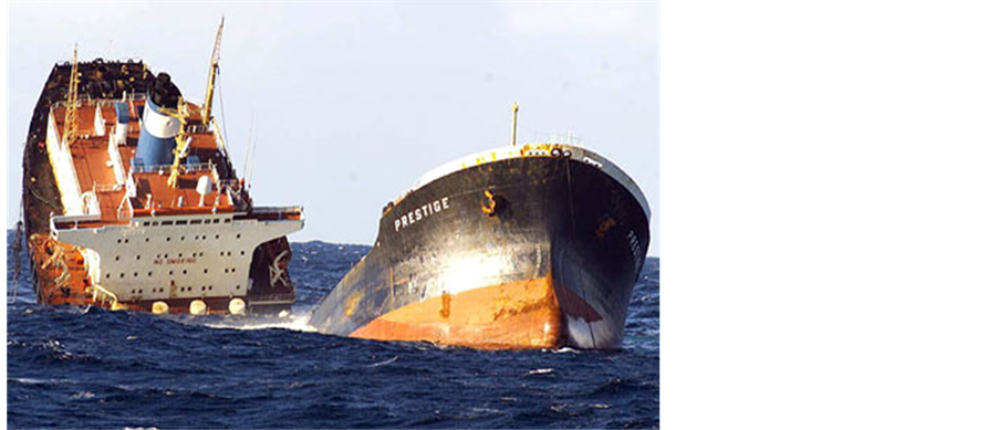
Figure 2. ERIKA tanker (year of built: 1975) after breaking on Dec. 12, 1999, at 60 miles from the coast of Brittany [6] .

Figure 3. PRESTIGE tanker (year of built: 1976) after breaking on November 13, 2002, at 30 miles off the Northwest coast of Spain [7] .
- adoption on 4 November 1993 of IMO Rez. A.744 (18) on enhanced survey system applicable to Bulk Carriers and Tankers;
- adoption on 23 November 1995 of IMO Rez. A.787 (19) on PSC responsibilities;
- adoption on 27 November 1997 of SOLAS Chapter XII on additional measures for safety of Bulk Carriers;
- adoption on 27 November 1997 of Bulk Carriers Safe Loading and Unloading Code (BLU Code) (IMO Rez. A.862 (20)).
The issuing in 1998 of the report on sinking of bulk carrier Derbyshire determined IMO to conduct new studies to enhance the requirements of its Conventions, so that in December 2002 SOLAS Convention was amended, by introducing new requirements in Chapter XII referring to bulk carriers, and in December 2004, Chapter XII of SOLAS was revised again and new requirements for double hull to bulk carriers were introduced. Furthermore, after this date, following documents were adopted:
- on 3 December 2004 the Code of Safe Practice for Solid Bulk Cargoes (BC Code) (Rez. MSC.193 (73));
- on 4 December 2008 the International Maritime Solid Bulk Cargoes Code (IMSBC Code) (Rez. MSC.268 (85));
- on 30 November 2011 the 2011 International Code on the Enhanced Programme of Inspections During Surveys of Bulk Carriers and Oil Tankers (2011 ESP Code) (Rez. A.1049 (27)) [8] .
Assessing the circumstances in which both bulk carriers and oil tankers had been lost through hull broken down in two pieces, it became obvious that they sank due to the fact that their longitudinal structure had a weak general strength and collapsed under distributed loads of cargoes on board, conditions of navigation and amidships long term fatigue strength.
As a result, for the safe operation of ships, the evaluation of their longitudinal strength is very important and shall be carried out during their life cycle, starting in design stage, continuing in building phase and after through systematic checking during entire operational life.
2. Longitudinal Strength Assessment of Seagoing Ships in Design Phase
In design phase, as hull is concerned, they define ship’s building and operational characteristics, navigation area, classification society or naval authority based on which rules the ship is classified, ship lines are established, ship subdivision is carried out based on operational requirements and stability and floatability criteria for intact or damaged condition, hull structural configuration is defined and materials for shipbuilding are selected [9] .
Dimensions of ship’s structural elements are established according to the rules of society which classify the ship or the technical norms of the authority which flag the built ship is flying, so that local strength requirements are fulfilled, as well as general strength requirements. Scantlings of transversal and longitudinal stiffeners of ship’s hull are performed firstly according to local strength requirements, and after scantlings of longitudinal stiffeners are performed according to general strength requirements. These scantling processes could be optimized with the aim to fulfill the above requirements with a minimum input of materials, energy and manpower.
It is worthy of note that the Common Structural Rules carried out by IACS for bulk carriers and oil tankers, which are considered by IMO as representing a part of tier IV within Goal Based Ship Construction Standards system, introduce net scantling approach, which require that net thickness prescribed by classification rules must be maintained during the whole operational life of the ship.
Assessment of fulfillment of longitudinal strength is performed by covering the following steps:
- numerical modeling of ship’s hull outside surface;
- determining of BONJEAN diagram;
- determining of weight distribution for ship in light condition;
- establishing of ship loading cases which will be analyzed;
- finding of equilibrium position of the ship in calm water;
- calculation of sectional stresses of ship’s hull in calm water;
- calculation of sectional stresses of ship’s hull on waves, determined according to rules of classification societies aligned to IACS unified requirements for longitudinal strength;
- calculation of strength characteristics of hull transversal sections;
- calculation of safe sectional stresses;
- verify satisfaction of longitudinal strength criteria in elastic range;
- verify satisfaction of ultimate longitudinal strength criteria;
- verify satisfaction of longitudinal fatigue strength criteria.
If at the end of this assessment they ascertain that one or more criteria are not satisfied, the assessment is recommenced, by adequately increasing the dimensions of longitudinal stiffeners and/or their number until when all criteria are fulfilled. They must observe that assessment of longitudinal strength in design phase is preliminary and the final one will be carried out after finalizing the ship construction, based on data from free floating and trim still water equilibrium condition (displacement and position of center of gravity for ship in light condition from the inclining test protocol).
3. Longitudinal Strength Assessment of Seagoing Ships during Construction Phase
During construction phase, the longitudinal strength assessment is ensured through verification by quality assurance compartments in shipyard and through technical survey carried out by a classification society or the naval authority whose flag the ship is flying, if:
- hull stiffeners are manufactured and assembled according to technical documentation for ship construction, approved by classification society or naval authority;
- stiffeners’ materials indicated in this documentation and welding materials have appropriate characteristics and are accompanied by certificates endorsed by recognized classification societies;
- standards on dimension limit system for shipbuilding are observed;
- welding technologies are accepted by relevant classification society and are observed;
- welders who perform stiffeners’ weld joints are authorized by classification society;
- welding processes are performed in the succession which induce the smallest strains in welded elements;
- welding processes are performed in appropriate atmospheric and thermal conditions;
- results of non-destructive examinations of welded joints are satisfactory;
- operators who carried out these examinations are authorized by the classification society;
- anti-corrosion protection is accomplished.
When construction is finished, an inclining experiment is conducted in order to determine lightweight displacement and position of center of gravity. Based on these data, load distribution is corrected and all general strength assessment is restarted, by finalizing in conformity with the rules of society which classified the ship, developing the loading manual and updating the database attached to the loading instrument, if that is requested by these rules.
Furthermore, for Bulk Carriers, the Manual on loading and unloading of solid bulk cargoes for terminal representatives shall be drawn up in conformity with the Code of Practice for the Safe Loading and Unloading of Bulk Carriers (BLU Code).
4. Longitudinal Strength Assessment of Seagoing Ships in Service
For safe operation of ships, they must perform the voyage loaded in accordance with loading manual or in accordance with a cargo-plan developed by the crew using loading instrument existing onboard, which was previously approved by the classification society. Loading and unloading of bulk carriers at terminals shall be carried out in accordance with Manual on loading/unloading sequences existing onboard or a Plan with loading/unloading sequences developed by the crew using loading instrument.
Likewise, the general strength assessment of ships in operation is conducted on the occasion of periodical surveys at 5 years interval, of intermediate surveys carried out at 2.5 years interval and of annual surveys. On the occasion of periodical and intermediate surveys, thickness measurements of stiffeners are carried out, by companies authorized by classification society or competent naval authority, measurements which shall be registered on forms to be kept in a folder onboard.
Measured reduced plating thicknesses are compared with maximum reduced thicknesses accepted, and in case these accepted reduced thicknesses are exceeded, the stiffeners are replaced. Maximum decreases accepted are usually corrosion allowances adopted at design stage.
Greater reduced thicknesses could be accepted, but in this case the assessment process of general and local strength of design phase shall be recommenced, with the exception that initial thicknesses of stiffeners are those of the Report of thicknesses’ measurements. Based on this assessment, restrictions in ship operation could be imposed and the Loading Manual, Stability Booklet, the Loading Instrument and Manual of loading/unloading sequences in case of bulk carriers shall be modified accordingly.
At annual survey, the followings shall be visually verified by sampling: the integrity of stiffeners, the presence onboard of Loading Manual and correct functioning of Loading Instrument.
Oil tankers and bulk carriers are subject of the enhanced programme of inspections in conformity with 2011 ESP Code (IMO Rez. A.1049 (27)) [8] and MSC.287 (87) [1] .
The Common Structural Rules for Bulk Carriers and Oil Tankers introduce the approach of stiffeners renewal criterion if the corrosion allowance was lost from initial thickness established by design.
Fatigue strength assessment is realized through detailed inspection and non-destructive examination of structural joints most exposed at variable loads indicated by designer, in order to track down possible cracks specific to fatigue phenomenon.
Those inspections will be carried out annually if ship age is greater than the actual operational age La, deduced by applying the equation:
 [years] (1)
where:
Dn is expected life of the ship [in years];
D is cumulative fatigue damage factor estimated for the expected life of the ship determined with the equation:
 (2)
(2)
k is the total number of spectrum blocs of stress variation for the period assessed, e.g. the expected life of the ship 25 years;
ni is the number of stress cycles in i-th stress block;
Ni is the number of alternating symmetrical cycles which could be endured by the material until fatigue failure determined from the corrected diagram S-N for Δσ = Δσi from Figure 4;
Δσi is the stress variation cycle from i-th stress block, in [MPa].
In case when cumulative damage factor D cannot be calculated sufficiently accurate, it can be found experimentally life of the ship using the structural joints most intensively stressed and testing them to fatigue in laboratory until they brake.
If these tests were carried out after Y years since the putting into service of the ship and in laboratory the residuary cumulative damage factor Dr, which remained until the break, is determined, then the real operational life of the ship Lr can be found using equation:
 [years] (3)
In case when cracks are discovered due to material fatigue before expected life of the ship expires, the fatigue strength of structural joints affected by this phenomenon will be reassessed, these joints will be redrawn and the cracked and tired stiffeners will be replaced by new redrawn stiffeners, and the inspection of joints will be carried annually.
Moreover, during the inspections, anticorrosive protection is verified and if it is found damaged, it will be reconditioned.
5. Critical Assessment of IACS Method for Calculation of Sectional Efforts Induced by Waves in Ship’s Hull Based on Sectional Efforts Calculated for Ship under Equivalent Quasi-Static Wave Design Load
5.1. Generals
In order to calculate sectional efforts due to waves, classification societies aligned their methods of calculus with

Figure 4. Diagram of stress-cycles [10] [11] .
that established by IACS based on the experience of its members, based on wide researches theoretical and experimental on models and ships, as well as based on statistical data regarding sea status, derived from measurements on large areas and long periods of time.
According to such IACS method ( [12] , Ch.S11), for the ships other than container ships, bulk carriers and double hull oil tankers, the vertical wave bending moment arising at any hull transverse section with probability of 10−8, at navigation in rough seas, parallel with waves’ propagation direction, is obtained from the following formula:
- for hogging condition:
 [kN×m] (4)
- for sagging condition:
 [kN×m] (5)
where:
L―length of ship [m];
B―breadth of ship [m];
kH = 190;
kS = 110;
FM―distribution factor defined in Table 1;
CB―block coefficient of ship for draught at full loading;
C―wave parameter (representing wave height corrected due to Smith effect) given by following equations:
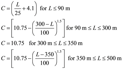 (6)
(6)
The vertical wave shear force at any hull transverse section, at navigation in rough seas, parallel with waves’ propagation direction, is obtained from the following formula:
 [kN] (7)
where:
FQ―distribution factor defined in Table 2 for positive and negative shear forces;
kQ = 30
For container ships, IACS proposed method ( [12] , Ch.S11A) and for bulk carriers and double hull oil tankers established method ( [11] , Ch4.sec4.3), similar as that above described.
Verification of sectional efforts induced by waves, calculated according to these IACS methods, may be accomplished through direct calculus and several methods based on hypothesis which reduce the complexity of calculus but not significantly affect the correctness of results beside real values were developed.
A first direct and effective method consists of ship quasi-static layout on wave.
This method ensures obtaining of accurate results for navigation in astern waves parallel with ship’s way.

Table 1. Distribution factor FM.
Table 2. Distribution factor FQ.
Note: .
.
It is theoretical and experimental proved the fact that additional vertical sectional efforts reach the maximum value when the top or hollow of the wave are amidships and the wave length is equal with the length of the ship.
For ship quasi-static layout on wave, Smith effect may be taken into account to reduce by 10% hydrostatic pressure in depth as a result of circular movement of wave particles.
Considering the ship quasi-static layout on trochoidal wave, the ship-equivalent quasi-static wave system equilibrium draught in a transversal section is given by formula:
- in case amidships is wave on hogging conditions (Figure 5);
 (8)
(8)
- in case amidships is in wave on sagging conditions (Figure 6),
 (9)
(9)
where:
F is a parameter obtained from transcendental equation:
 (10)
(10)
l―wave length [m]. Wave length is considered equal with ship’s length, L;
To―the system equilibrium draught at aft ship’s extremity referring the position of the head ship-equivalent quasi-static. wave medium plane into the ship's base plane reference (see Figure 5 and Figure 6) in [m];
y―the system equilibrium trim at aft ship’s extremity referring the position of the head ship-equivalent quasi-static. wave medium plane into the ship's base plane reference (see Figure 5 and Figure 6) in [rad];
h―wave height in [m];
L―length of ship in [m].
For simplicity, keeping accuracy of the calculations within reasonable limits, the wave also can be regarded as cosine form and then the ship-equivalent quasi-static wave system equilibrium draught in a transversal section is given by formula:
- in case amidships is wave on hogging conditions (Figure 5);
 (11)
(11)
- in case amidships is in wave on sagging conditions (Figure 6),
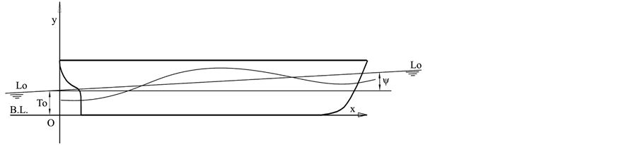
Figure 5. Ship quasi-static layout on wave on hogging conditions.
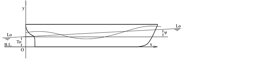
Figure 6. Ship quasi-static layout in wave on sagging conditions.
 (12)
(12)
The additional sectional efforts induced by wave alongside ship are obtained by formulae:
- additional shear force alongside ship:
 (13)
(13)
- additional bending moment alongside ship:
 (14)
(14)
where:
QTW(x) is total shear force at ship quasi-static layout on wave determined for draughts given by Formula (8), (9), (10) or (11) in [kN];
QSW(x) is shear force at quasi-static layout on still water, in [kN];
MTW(x) is total bending moment at ship quasi-static layout on wave determined for draughts given by Formula (8), (9), (10) or (11) in [kN×m];
MSW(x) is bending moment at quasi-static layout on still water, in [kN×m];
The calculus of additional sectional efforts appearing in the hull of a ship quasi-static layout on wave will be further performed by using a FORTRAN code for ship quasi-static head wave equilibrium iterative approach whose calculation method is presented in [13] .
The main flow chart of the authors’ code is shown in Figure 7.
Note 1: Equilibrium Requirements
The ship is in the quasi-static equilibrium on water, if the displacement is equal with the buoyant force and if its center of gravity G is on the same vertical with center of buoyancy C (Figure 8). In the code method they consider that the ship’s equilibrium is performed if the following relations are fulfilled:


where:
 ―specific gravity of water;
ka―appendages coefficient;
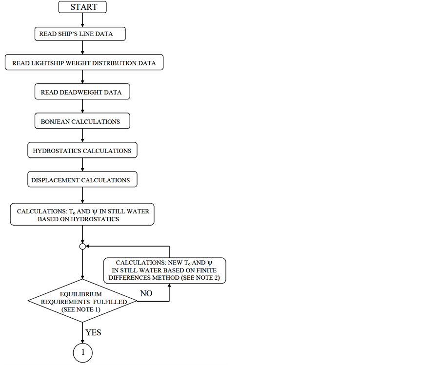
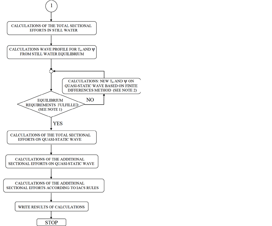
Figure 7. The main flow chart of the author’s code.

Figure 8. Ship’s quasi-static equilibrium on water.
 ―ship’s displacement;
VC―volumul of immersed hull;
xG, zG―coordinates of the center of gravity of the ship;
xC, zC―coordinates of the center of buoyancy.
 ―the maximum acceptable deviation displacement (for a precise balance, shall be adopted
 = 0.0001 Δ);
 ―maximum deviation from the vertical plane transverse of the vessel’s center of gravity and center of buoyancy (for a precise balance, shall be adopted
 = 0.0001 T).
Note 2: Finite Differences Method
Equilibrium position is found by successive calculations based on finite difference method, determining the parameters To and ψ for this position based on equilibrium conditions. To this purpose, it starts from an initial floating position and they consider that variation of area immersed Ω of a theoretical couple according to the draught T, and static moment variation of this area C in relation to base line, are linear over a small draught interval δ. This leads to solving a system of two equations having as unknowns the increasing of the draught ζ and the trim angle ψ, on reaching the equilibrium, as follows:

where:
 is submerged area of theoretical couplings for initial buoyancy;
 is submerged area of the same draft couplers for increased buoyancy with value δ from the initial buoyancy;
C0 is static moment in relation to base line of submerged area of theoretical couplings for initial buoyancy;
C is static moment static in relation to base line of submerged area of the same draft couplers for increased buoyancy with value δ from the initial buoyancy.
5.2. Test of the Code to a Parallelepiped Barge
The test of calculus of the cod was carried out to a parallelepiped barge with uniform weight distribution of 100 t/m, having the following main characteristics:
Lmax = 100.00 m―maximum length;
L = 100.00 m―length at water line;
B = 20.00 m―breadth;
D = 10.00 m―depth;
T = 5.00 m―draught on still water.
Sea water density was taken 1.025 t/m3.
The calculus were performed laying the barge on a quasi-static wave with height corrected by Smith effect equal to value C determined with IACS Formula (6), i.e. equal with 7.92 m and length equal to length of ship, (the real wave having height of 8.80 m, period of 8.0 s and length of 100 m, is found with probability of 0.22% as could be seen from statistical measurements presented in [10] ).
For this theoretical barge at its quasi-static layout on trohoidal wave, following values have been obtained through direct not automatic calculus:
- positive/negative maximum shear force: +/−12,380 kN;
- hogging/sagging maximum bending moment: +/−394,999 kN×m;
- To = 5.370 m;
- ψ = 0.00 deg.
The results obtained by code for this wave, are:
- on wave crest:
- positive maximum shear force: 12,381 kN;
- negative maximum shear force: −12,381 kN;
- hogging bending moment: 395,127 kN×m;
- To = 5.370 m;
- ψ = 0.00 deg.
- in wave hollow:
- positive maximum shear force: 12,381 kN;
- negative maximum shear force: −12,381 kN;
- sagging bending moment: −395,120 kN×m;
- To = 5.370 m;
- ψ = 0.00 deg.
Also, for this barge at its quasi-static layout on cosine wave, following values have been obtained through direct not automatic calculus:
- positive/negative maximum shear force: +/− gγCLB/4π = +/−12,681 kN;
- hogging/sagging maximum bending moment: +/− gγCL2B/4π2 = +/−403858 kN×m;
- To = 4.878 m;
- ψ = 0.00 deg.
The results obtained by the code for same wave, are:
- on wave crest:
- positive maximum shear force: 12,675 kN;
- negative maximum shear force: −12,675 kN;
- hogging bending moment: 403,449 kN×m;
- To = 4.878 m;
- ψ = 0.00 deg.
- in wave hollow:
- positive maximum shear force: 12,675 kN;
- negative maximum shear force: −12675 kN;
- sagging bending moment: −403,448 kNm;
- To = 5.00 m;
- ψ = 0.00 deg.
The results above show that differences between manual and code calculations are under 0.1% and therefore the accuracy of the code is proved.
It is worthy of note that in case of barge, differences between values of additional for ship layout on trochoidal wave and cosine wave are less than 2.5% which allow to approximate real trochoidal wave with a wave of cosine form wherewith technical assessments could be carried out effortless but maintaining correctness of results in acceptable limits.
The additional vertical sectional efforts appearing in the hull of a ship induced by wave obtained according to IACS are:
- hogging maximum bending moment: 300,960 kN×m
- sagging maximum bending moment: −296,208 kN×m
- positive maximum shear force: 8078 kN
- negative maximum shear force: −8208 kN
The gaps for this barge are: for additional bending moment 25%, and for additional shear forces 35%.
5.3. Application of the Methodology to a General Cargo Ship
The methodology for calculation of additional sectional efforts appearing in the hull of a ship quasi-static layout on wave was applied to a general cargo ship of 15,000 dwt shown in Figure 9.
The main characteristics of the ship are given below, the transversal line plan is shown in Figure 10 and the distribution weights are presented in Figure 11.
Lmax = 162.30 m -maximum length;
L = 155.00 m-length at water line;
B = 22.20 m-breadth;
D = 13.40 m-depth;
T = 10.10 m-draught.
This ship was quasi-static layed out on wave with height corrected by Smith effect equal to value C determined with Formula (6), i.e. equal with 8.997 m and length equal to length of ship, (the real wave having height of 10.000 m, period of 9.96 s and length of 155 m, is found with probability of 0.1% as could be seen from statistical measurements presented in [10] ). The results of the calculus performed by the code are presented below and graphic in Figure 12 and Figure 13.
The results obtained at quasi-static layout on trohoidal wave, are:
- on wave crest:
- maximum positive shear force: 15,164 kN;
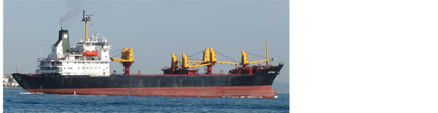
Figure 9. The analyzed general cargo ship.

Figure 10. The transversal line plan of the general cargo ship analyzed.
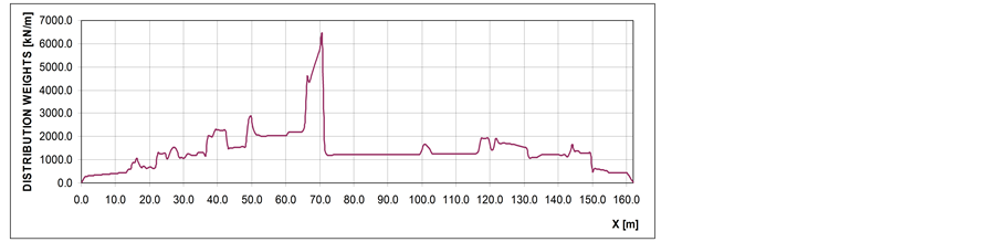
Figure 11. The distribution weights of the general cargo ship analyzed.
- maximum negative shear force: −14,314 kN;
- hogging bending moment: 599,373 kN×m;
- To = 8.119 m;
- ψ = 0.677 deg.
- in wave hollow:
- maximum positive shear force: 17,587 kN;
- maximum negative shear force: −17,111 kN;
- sagging bending moment: −797,591 kN×m;
- To = 13.117 m;
- ψ = −0.217 deg.
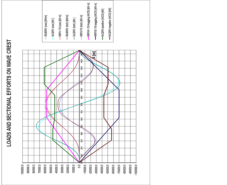
Figure 12. Additional sectional efforts at quasi-static layout on trochoidal wave on hogging conditions.
The results obtained at quasi-static layout on cosine wave, are:
- on wave crest:
- maximum positive shear force: 14,622 kN;
- maximum negative shear force: −14,115 kN;
- hogging bending moment: 589,390 kN×m;
- To = 7.599 m;
- ψ = 0.658 deg.
- in wave hollow:
- maximum positive shear force: 18,003 kN;
- maximum negative shear force: −18,943 kN;
- sagging bending moment: −838,078 kN×m;
- To = 12.630 m;
- ψ = −0.297 deg.
According to IACS method ( [12] , Ch.S11), additional efforts induced by a wave have been determined for this general cargo ship. The results obtained with this method are:
- hogging maximum bending moment: 574,646 kN×m;
- sagging maximum bending moment: −700,266 kN×m;
- positive maximum shear force: 12,353 kN;
- negative maximum shear force: −11,365 kN.
They find out that additional sectional efforts obtained through direct calculus at ship quasi-static layout on
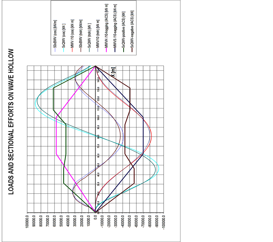
Figure 13. Additional sectional efforts at quasi-static layout on trochoidal wave on sagging conditions.
wave are greater than those obtained in conformity with IACS method. Consequently the direct calculus is more covering in what safety of ship is concerned.
Maximum additional bending moments determined through ship quasi-static layout on wave are about 14% greater than those determined based on IACS method and in case of the shear forces, differences are much bigger, reaching 51%, which means that this method leads getting of ship under scantling regarding sectional efforts induced by waves.
Also, it is noted that in case of the general cargo ship, differences between values of additional for ship quasi-static layout on trochoidal wave and cosine wave are less than 10.5%.
5.4. Application of the Methodology to a Bulk Carrier
Also, the methodology was applied to a bulk carrier of 65,000 dwt shown in Figure 14. The main characteristics of the ship are given below, the transversal line plan is shown in Figure 15 and the distribution weights are presented in Figure 16.
Lmax = 254.10 m―maximum length;
L = 250.00 m―length at water line;
B = 32.20 m―breadth;
D = 17.00 m―depth;

Figure 14. The analyzed bulk carrier.
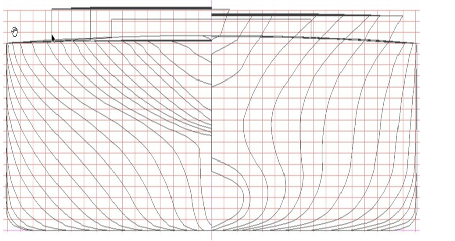
Figure 15. The transversal body lines of the analyzed bulk carrier.

Figure 16. The weight Distribution of the analyzed bulk carrier.
T = 12.3 m―draught.
This ship was quasi-static layed out on wave with height corrected by Smith effect equal to value C determined with Formula (6), i.e. equal with 10.396 m and length equal to length of ship, (the real wave having height of 11.551 m, period of 12.65 s and length of 250 m, is found with probability of 0.017% as could be seen from statistical measurements presented in [10] ). The results of the calculus performed by the code are presented below and graphic in Figure 17 and Figure 18.
The results obtained at quasi-static layout on trohoidal wave, are:
- on wave crest:
- maximum positive shear force: 51,541 kN;

Figure 17. Additional sectional efforts at quasi-static layout on trochoidal wave on hogging conditions.
- maximum negative shear force: −49,851 kN;
- hogging bending moment: 3,547,379 kN×m;
- To = 10.623 m;
- ψ = 0.958 deg.
- in wave hollow:
- maximum positive shear force: 54,467 kN;
- maximum negative shear force: −54,421 kN;
- sagging bending moment: −4,024,886 kN×m;
- To = 13.148 m;
- ψ = −0.904 deg.
The results obtained at quasi-static layout on cosine wave, are:
- on wave crest:
- maximum positive shear force: 50,134 kN;
- maximum negative shear force: −48828 kN;
- hogging bending moment: 3,468,118 kN×m;
- To = 10.116 m;
- ψ = −0.930 deg.
- in wave hollow:

Figure 18. Additional sectional efforts at quasi-static layout on trochoidal wave on sagging conditions.
- maximum positive shear force: 55,983 kN;
- maximum negative shear force: −56,032 kN;
- sagging bending moment: −4,132,476 kN×m;
- To = 12.734 m;
- ψ = −0.922 deg.
According to IACS method ( [12] , Ch4.sec4.3), additional efforts induced by a wave have been determined for this bulk carrier. The results obtained with this method are:
- hogging maximum bending moment: 3,209,681 kN×m;
- sagging maximum bending moment: −3,459,289 kN×m;
- positive maximum shear force: 37,737 kN;
- negative maximum shear force: −35,015 kN.
They find out that additional sectional efforts obtained through direct calculus at ship quasi-static layout on wave are greater than those obtained in conformity with IACS method. Consequently the direct calculus is more covering in what safety of ship is concerned.
Maximum additional bending moments determined through ship quasi-static layout on wave are about 16% greater than those determined based on IACS method and in case of the shear forces, differences are much bigger, reaching 55.4%, which means that this method leads getting of ship under scantling regarding sectional efforts induced by waves.
Also, it is noted that in case of the bulk carrier, differences between values of additional for ship layout on trochoidal wave and cosine wave are less than 3%.
6. Discussions, Conclusions and Proposals
In the paper, the problems on the sea going ships safety have been treated. The requirements of the IACS rules and methods for estimating the ship hull general strength have been presented. The methods are illustrated by two examples of the sectional efforts estimation. According to the results, certain inconveniencies after the great accidents occurring in the last decades have been expressed by the shipbuilders and operators.
The under scantling of ships in terms of wave-induced sectional efforts is confirmed by data from a Formal Safety Assessment (FSA) on Bulk Carrier Safety between 1978 and August 2000 conducted by Japan for the IMO Maritime Safety Committee [14] . The data showed that from 1126 of fatalities, 69.70% were due to side shell failures (785). Also, it was found that from 1982 to 2001, the side shell failures led to the sinking of 72 classic bulk carriers and a single with the double bottom [15] .
Furthermore, the ships were broken through deck collapse which meant that they were under scantling for sagging bending moment and consequently revising the formula for its calculation was required.
Problems come into attention of IMO, which are concluded in [16] , that the minimum thickness of side shell for bulk carriers must have at least the value given in following formulae:
 ;
;
 .
.
where:
c = 1.15 for the frame webs in way of the foremost hold;
c = 1 for the frame webs in way of other holds.
L is the ship’s length.
Furthermore, this organization imposed since 1st July 2006 through Regulation XII/6.2 of SOLAS Convention, that bulk carriers over 150 m in length to have double side [17] .
Taking into consideration those presented hereinbefore, in order to improve ship construction safety, they propose that:
- factor kH from Formula (4) to be increased with about 10% i.e. to have the value of 210 instead of 190;
- factor kS from Formula (5) to be increased with about 20% i.e. to have the value of 130 instead of 110;
- factor kQ from Formula (7) to be increased with 50% i.e. to have the value of 45 instead of 30.
By applying these revised formulae, following values have been obtained for the general cargo ship:
- hogging maximum bending moment: 635,135 kN×m;
- sagging maximum bending moment: −827,587 kN×m;
- positive maximum shear force: 18,529 kN;
- negative maximum shear force: −17,047.5 kN.
And following values are for the bulk carrier:
- hogging maximum bending moment: 3547,542 kN×m;
- sagging maximum bending moment: −408,8251 kN×m;
- positive maximum shear force: 56,605 kN;
- negative maximum shear force: −52,522 kN.
According to the new proposal, in the case of the general cargo ship, for additional maximum bending moments differences are less than 6% and for additional maximum shear forces differences are less than 5%.
In the case of the bulk carrier, for additional maximum bending moments differences are less than 1% and for additional maximum shear forces differences are less than 4%.
These differences could be considered as acceptable.
It is worth noting that formulae are revised only relating to sectional efforts determined for ship quasi-static layout on wave. It is necessary that such analysis should be carried out for dynamic layout on wave as well and if bigger efforts are obtained, this means revising again the afore-mentioned formulae.
From the assessment carried out, it shows that IACS formulae for calculation of additional sectional efforts induced by waves must be corrected because these efforts are exceeded in real situations in which ship layout is quasi-static on wave, as in cases where ship navigates with wave from astern. If uncorrected IACS formulae continue to be used, imposes as a first measure to improve ship construction safety since design phase, the determination of sectional efforts at quasi-static layout on wave through direct calculations and if those have greater values as those obtained with IACS formulae, the scantling of longitudinal structure of ship will be carried out taking into account of respective values.
Cite this paper
DumitruLupascu,IonelChirica, (2015) Assessment of Seagoing Ships Longitudinal Strength in the Context of International Rules, Important Factor for Safe Operation. World Journal of Engineering and Technology,03,291-310. doi: 10.4236/wjet.2015.34029
References
- 1. IMO, Resolution MSC.287 (87) on 20 May 2010—Adoption of the International Goal-Based Ship Construction Standards for Bulk Carriers and Oil Tankers.
- 2. Lloyd’s Register, Rules and Regulations 2015.
- 3. View Market Reports 2015. Electronic Document.
http://www.allcountries.org/uscensus/1095_merchant_vessels_ships_and_tonnage_lost.html - 4. Safety and Shipping Review (2014) Electronic Document.
http://www.imo.org/en/KnowledgeCentre/ShipsAndShippingFactsAndFigures/Statisticalresources/Casualties/Documents/FSI%2020%20INF-17%20%20Casualty%20statistics%20-%20loss%20of%20life%20from%202006%20to%20date.pdf - 5. Ship Structure Committee, BULK CARRIERS: Design, Operation, and Maintenance Concerns for Structural Safety of Bulk Carriers. Electronic Document.
http://www.shipspotting.com/gallery/photo.php?lid=810893 - 6. Steamship Mutual, Erika—The Black Tide. Electronic Document.
http://www.steamshipmutual.com/loss-prevention/ErikaDVD.htm - 7. Ship Structure Committee, PRESTIGE: Complete Hull Failure in a Single-Hull Tanker. Electronic Document.
http://www.shipstructure.org/case_studies/Prestige.pdf - 8. IMO, Resolution A.1049 (27) on 30 November 2011—International Code on the Enhanced Programme of Inspections during Surveys of Bulk Carriers and Oil Tankers, 2011 (2011 ESP Code).
- 9. Chirica, I., Lupascu, D. and Beznea, E.F. (2015) Design Solutions for Jack up Platform Retrofitting. World Journal of Engineering and Technology, 3, 134-148.
http://dx.doi.org/10.4236/wjet.2015.33015 - 10. ABS (2004) Guidance Notes on Spectral-Based Fatigue Analysis for Vessels. Electronic Document.
http://ww2.eagle.org/content/dam/eagle/rules-and-guides/current/conventional_ocean_service/125_sfaforvessels/ship_sfa_guide_e-feb12.pdf
- 11. IACS (2015) Common Structural Rules for Bulk Carriers and Double Hull Oil Tankers.
- 12. IACS (2012) Requirements Concerning Strength of Ships.
- 13. Lupascu, D. (2013) Methods for Analysis of Global and Local Strength of Ships (Scientific Report No. 2). University Dunarea de Jos of Galati, Galati.
- 14. IMO Maritime Safety Committee (2002) MSC75/5/2, Report of FSA Study on Bulk Carrier Safety.
- 15. Andreas, I. (2010) Ultimate Longitudinal Strength of Corroded and Damaged Bulk Carriers. Doctorate Thesis, “Dunarea de Jos” University of Galati, Galati.
- 16. IMO, MSC.168 (79) on 9 December 2004—Standards and Criteria for Side Structures of Bulk Carriers of Single-Side Skin Construction.
- 17. IMO (1974) International Convention for the Safety of Life at Sea (SOLAS).
NOTES

*Corresponding author.