Optics and Photonics Journal
Vol.3 No.2(2013), Article ID:33068,8 pages DOI:10.4236/opj.2013.32035
Study of OFDM Technique on RoF Passive Optical Network
Department Electrical and Computer Engineering, University of Denver, Denver, USA
Email: fahadma@hotmail.com
Copyright © 2013 Fahad Almasoudi et al. This is an open access article distributed under the Creative Commons Attribution License, which permits unrestricted use, distribution, and reproduction in any medium, provided the original work is properly cited.
Received January 30, 2013; revised March 3, 2013; accepted March 12, 2013
Keywords: OFDM; RoF; PON; ONU; RoF-OFDM; ISI; ICI; QAM
ABSTRACT
The combination of radio over fiber (RoF) and orthogonal frequency division multiplexing (OFDM) techniques has resulted in a high-data-rate at lower cost in the last mile of wireless networks. This paper investigates the use of the OFDM as a modulation technique for radio over fiber (RoF) in passive optical network (PON). A laser source of 1550 nm wavelength was used with 100 km, 140 km and 288 km single mode fiber. In the OFDM-PON a passive optical splitter of ratio 1:2 is used to connect two optical network units (ONUs). A 10 Gbits/sec transmission bit rate is used to simulate the RoF-OFDM-PON system. The proposed system can provide a flexible, cost effective and significant high data rate.
1. Introduction
The demand for high speed data rate and high capacity of bandwidth has increased due to recent advances in technology in the access networks bandwidth. The integration of wireless communication networks and fiber optic networks has provided a large number of advantages such as a high data rate, larger bandwidth and low consumption of power. One of the promising techniques to support high data rates and bandwidth is with the use of passive optical network (PON). OFDM is a practical technique used to improve the efficiency of the PON used in the long haul application. OFDM is an efficient technique when used in fiber optical networks due to its ability to reduce chromatic dispersion in the optical fiber [1]. Because of its limited Inter Symbol Interference (ISI), and lower computational complexity OFDM has been widely used in the field of wireless communication. OFDM affords the high transmission rate and the preferred spectrum utilization with low cost optical components by using different types of M-array modulation, such as Quadrature Amplitude Modulation (QAM) or Phase-ShiftKeying (PSK) [2].
OFDM is established on the parallel transmission in frequency domain. ISI can be cancelled in OFDM because the symbols are long. The modulator in the OFDM contains an M-point of inverse discrete Fourier transform (IDFT), subcarrier mapping, conversion from serial to parallel, and the addition of a cyclic prefix and filter before each OFDM symbol. A small portion of the last part of the OFDM symbol is duplicated to the prefix of the similar OFDM symbol. The prefix helps to cancel ISI and intercarrier interference (ICI), and to let the channel matrix to be circular. The IDFT in the receiver and its corresponding discrete Fourier transform (DFT) are applied with the inverse fast Fourier transform (IFFT) and the fast Fourier transform (FFT), correspondingly as shown in Figure 1 [3].
This paper will concentrate on presenting and studying the efficiency of OFDM technique in RoF-PON architecture for downstream through M-array QAM modulation.
2. System Design
The main goal of this paper is to investigate the integration of RoF (Radio over Fiber) with OFDM-PON (Passive Optical Network). The system design as shown in Figure 2 includes three main parts which are the transmission part, the transmission link and the receiver part. For the transmission part, in order to generate OFDM signal, the input signal needs to be connected to M-QAM sequence generator, which is in our case 4-QAM followed by OFDM modulator [4]. After that, to integrate the OFDM signal RF or to convert the OFDM signal to RF, a RF-IQ mixer is used [4-6]. The resulting signal is
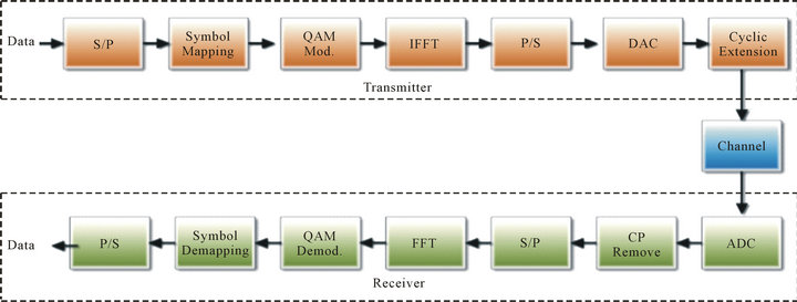
Figure 1. OFDM block diagram.
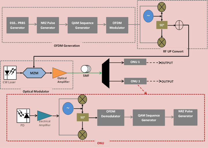
Figure 2. RoF-OFDM-PON system design.
combined with the light wave from the CW laser through an external modulator, Mach-Zehnder modulator [7-9]. The resulting signal from the modulator is transmitted over single mode optical fiber followed by a 1:2 optical splitter to make the use of the Passive Optical Network. After that, the resulting signal from the splitter is transmitted to two optical network units (ONUs). Each ONU contains a photo detector to convert the optical signal to Electrical signal, RF-IQ demux, OFDM demodulator and 4-QAM sequence generator.
To design and implement the system OptiSystem V.11 simulation software is used [10]. After designing the system, several parameters must be taken under consideration to get the right results, these parameters are defined in Table 1.
2.1. RoF-OFDM-PON-100 km-SMF System Design
The RoF-OFDM-PON design for 100 km SMF is shown in Figure 3. The OFDM transmitter was defined for 4-QAM (2 bit-per-symbol). The signal from the OFDM generation was modulated by LiNbO3 Mach-Zehnder modulator with CW laser of 193.1 THz. The modulated signal was transmitted over 100 km-SMF with EDFA of 20 dB before the SMF and EDFA of 20 dB after the SMF. The signal from the SMF was detected by a photodiode (PD). After that, the RF signal was demodulated by Quadrature demodulator followed by an OFDM Demodulator and 4-QAM decoder to get the data.
2.2. RoF-OFDM-PON-140 km-SMF System Design
Figure 4 shows the RoF-OFDM-PON design for 140 km SMF. The OFDM transmitter was defined for 4-QAM (2 bit-per-symbol). The signal from the OFDM generation was modulated by LiNbO3 Mach-Zehnder modulator with CW laser of 193.1 THz. The modulated signal was transmitted over 140 km-SMF; however, the signal was corrupted due to dispersion from the long distance. So, in order to solve this problem the EDFA before the SMF was increased to 25 dB and the EDFA after the SMF was increased to 40 dB. After that, the signal from the SMF was detected by a photodiode (PD). After that, the RF signal was demodulated by Quadrature demodulator followed by an OFDM Demodulator and 4-QAM decoder to get the data. After modifying the EDFAs the signal improved significantly.
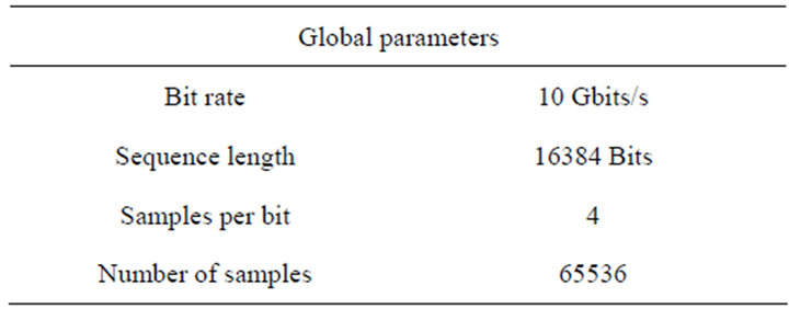
Table 1. Simulation global parameters.
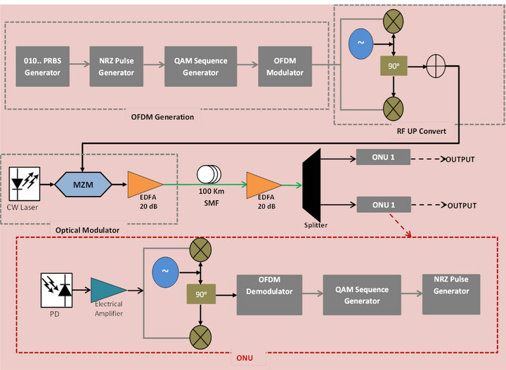
Figure 3. RoF-OFDM-PON-100 km-SMF system design.
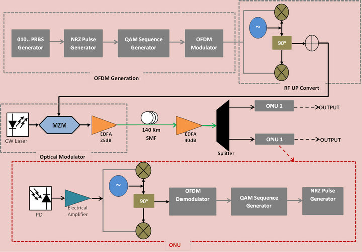
Figure 4. RoF-OFDM-PON-140 km-SMF system design.
2.3. RoF-OFDM-PON-288 km-SMF with DCF System Design
The RoF-OFDM-PON design for 100 km SMF is shown Figure 5. After increasing the SMF length to 140 km, different lengths was tested such as: 180-200-288 but even with increasing the EDFAs gain the signal was corrupted. The signal corruption is due to the chromatic dispersion because of the long distance and power attenuation. In order to solve this problem dispersion compensation must be used. So, to extend the transmission distance symmetric Dispersion Compensation Fiber (DCF) of 2XDCF and 2XSMF was designed to compensate the dispersion [12-14]. The SMF dispersion is 16 ps/nm/km and length of 120 km. for the DCF the dispersion is −80 ps/nm/km and length of 24 km. the SMF is followed by 25 dB EDFA to amplify the signal. The signal from the SMF was detected by a photodiode (PD). After that, the RF signal is demodulated by Quadrature demodulator followed by an OFDM Demodulator and 4-QAM decoder to get the data.
3. Results
The constellation diagram describes the signal that digitally modulated, presenting it as a two-dimensional dispersion diagram. Figure 6 displays a pure electrical constellation scheme for the signal transmission for 4-QAM digital modulator 2 bits at the transmitter. Constellation diagrams can measure the distortion and interference in a signal.
Figure 7 displays the constellation of the 4QAM signal at the receiver when the length of the fiber is 100 km. The signal begins to become indistinct, because Rayleigh scattering, chromatic dispersion, power attenuations, and noise when it is compared with the transmission signal in Figure 6. The blue points describe the noise that comes from the laser diode and the red points represent the signal.
The RF spectrum of 4-QAM for 7.5 GHz carrier frequency and 10 MHz bandwidth is shown in Figure 8. The signal is distributed by SMF of 100 km length. The photo detector changes the optical signal to an electrical signal. The power of the RF is measured at −60 dBm. The noise, which is showed in green color, is measured at −100 dB. The signal is showed in blue color.
The display of the electrical constellation of the signal after 140 km is shown in Figure 9, it is clearly shows that the signal is corrupted. The signal started broadening
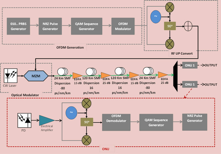
Figure 5. RoF-OFDM-PON-288 km-SMF with DCF system design.
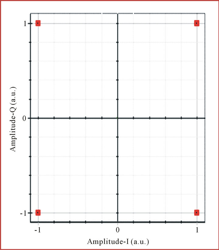
Figure 6. Constellation diagram for 7.5 GHz signal transmissions at transmitter.
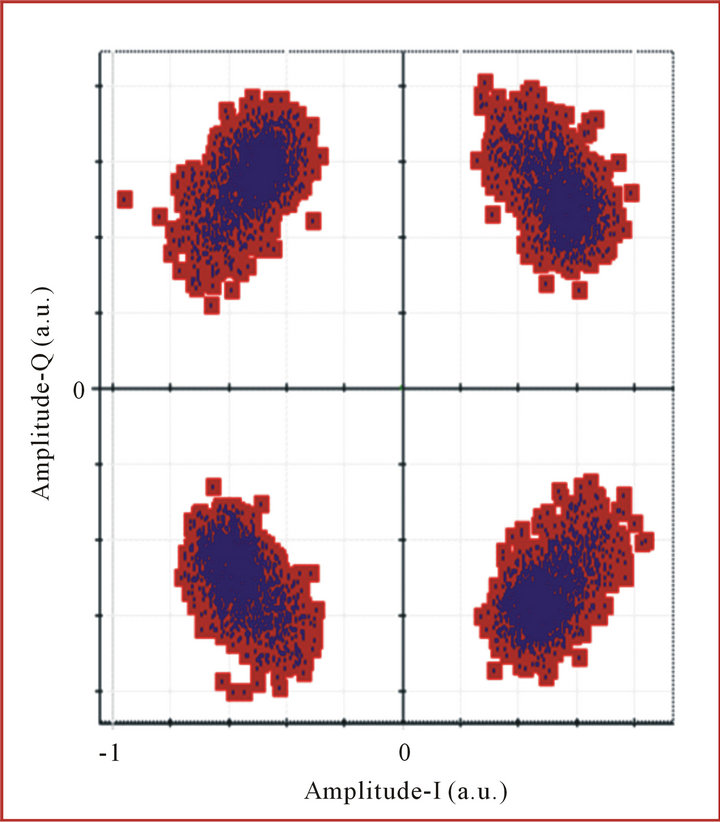
Figure 7. The Constellation diagram for SMF of 100 km length.
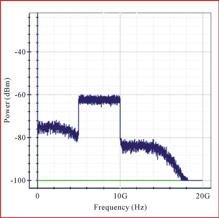
Figure 8. RF spectrum for 100 km SMF.
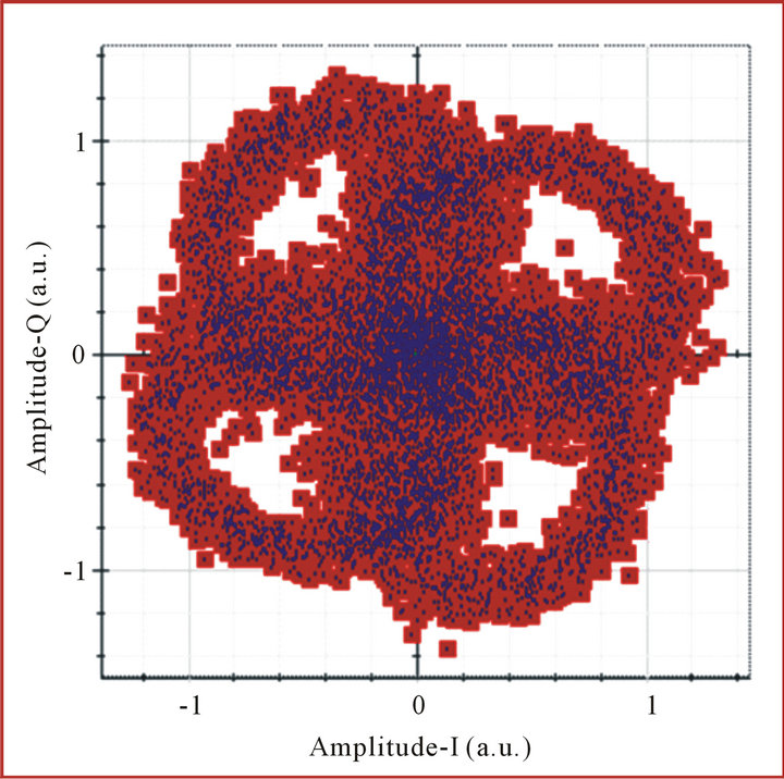
Figure 9. Signal constellation of 140 km SMF length.
when the length of the fiber exceeds 100 km. This broadening occurred in the signal due the positive dispersion in the SMF. The chromatic dispersion is a major issue in the SMF when the signal travels for a long distance. It can affect the quality of the signal and also it can increase the attenuation power.
Figure 10 presents the constellation diagram of the 140 km SMF. The EDFAs gains are increased to 25 and 40 dB, respectively to take off the dispersion from the signal. Consequently, the signal shows a great improvement when it is compared by Figure 9.
Figure 11 presents the RF spectrum of 4-QAM for 7.5
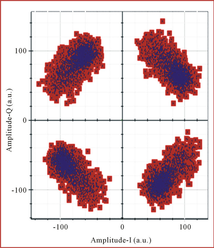
Figure 10. Constellation diagram of 140 km SMF for EDFAs power of 25 and 40 dB, respectively.
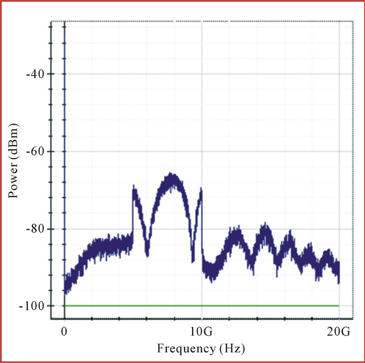
Figure 11. RF spectrum for 140 km SMF.
GHz carrier frequency and 10 MHz bandwidth. The signal is distributed by SMF of 140 km length. The result displays that the power is reduced from −60 dBm to −65 dBm when the SMF length is increased to 140 km. the reduction in the RF power is because of the attenuation in the SMF.
Afterwards, the distance of the signal transmission is increased to 288 km fiber length. The power of the EDFAs is raised to more than 75 dB but the corruption of the signal is still has not improved, as displayed in Figure 12. This means that increasing the power of the EDFAs cannot affect the quality of the signal or a fiber length of 288 km, because the EDFA just amplifies efficiently, when the signal transmitted gets low power.
Figure 13 shows the constellation diagram of 4-QAM for a fiber length of 288 km. It is clearly that the quality
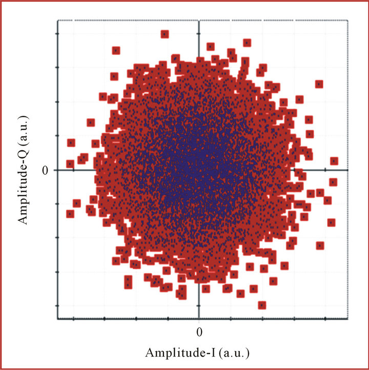
Figure 12. Constellation diagram of 288 km SMF.
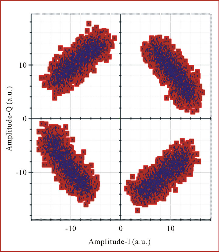
Figure 13. The constellation diagram for RoF (SMF-DCF) for SMF 288 km.
of the signal is much improved after using dispersion compensation fiber (DCF).
4. Conclusion
In this paper we studied and analyzed RoF-OFDM-PON over 100 km, 140 km, and 288 km with a DCF single mode fiber by OptiSystem simulation software. In the OFDM-PON a passive optical splitter with a ratio 1:2 was used to connect two optical network units (ONUs). A 10 Gbits/sec transmission bit rate for the total system was used to simulate the OFDM-PON system. To analyze the performance of the system, an oscilloscope visualizer was used. Furthermore, to study a RF signal and the optical signal, a RF spectrum analyzer and optical spectrum analyzer were used. The Quadrature-Phase and In-Phase signals were analyzed using Electrical Constellation visualizer. The resulting data proved the effectiveness of the RoF-OFDM-PON. The study suggests that this system is not only flexible and cost effective, but also provides a significant high data rate.
REFERENCES
- C. Chow, C. Yeh, C. Wang, C. Wu, S. Chi and C. Lin, “Study of OFDM Signal for Broadband Optical Access Networks,” IEEE Journal on Selected Areas in Communications, Vol. 28, No. 6, 2010, pp. 800-807. doi:10.1109/JSAC.2010.100805
- N. Nowshin, A. Arifuzzman and M. Tarique, “Demonstration and Performance Analysis of RoF Based OFDMPON System for Next Generation Faber Optic Communication,” International Journal of Computer Networks & Communiations, Vol. 4, No. 1, 2012, p. 193.
- N. Gomes, P. Monteiro and A. Gameiro, “Next Generation Wireless Communications using Radio over Fiber,” John Wiley & Sons, Ltd., West Sussex, 2012. doi:10.1002/9781118306017
- Y. Wong, S. Idrus and I. Ghani, “Performance Analysis of the OFDM Scheme for Wireless over Fiber Communication Link,” International Journal of Computer Theory and Engineering, Vol. 4, No. 5, 2012, p. 807.
- W. Wen, J. Liu, W. Lin and G. Sun, “Millimeter-Wave Photonic Techniques for Radio-over-Fiber Systems,” 14th International Conference on Advanced Communication Technology, PyeongChang, 19-22 February 2012, pp. 1031- 1034.
- L. Mehedy, M. bakaul, A. Nirmalathas and E. Skafidas, “OFDM versus Single Carrier Towards Spectrally Efficient 100 Gb/s Transmission with Direct Detection,” Journal of Optical Communications and Networking, Vol. 4, No. 10, 2012, pp. 779-789. doi:10.1364/JOCN.4.000779
- L. Roselli, V. Borgioni, F. Zepparelli, F. Ambrosi, M. Comez, P. Faccin and A. Casini, “Analog Laser Predistortion for Multiservice Radio-Over-Fiber Systems,” Journal of Lightwave Technology, Vol. 21, No. 5, 2003, pp. 1211-1223. doi:10.1109/JLT.2003.810931
- A. Alateeq, K. Alatawi, F. Almasoudi and M. A. Matin, “Design of Broadband RoF PON for the Last Mile,” Communications and Network, Vol. 4, No. 4, 2012, pp. 269- 277. doi:10.4236/cn.2012.44031
- N. J. Gomes, M. Morant, A. Alphones, B. Cabon, J. E. Mitchell, C. Lethien, M. Csörnyei, A. Stöhr and S. Iezekiel, “Radio-over-Fiber Transport for the Support of Wireless Broadband Services,” Journal of Optical Networking, Vol. 8, No. 2, 2009, p. 156. doi:10.1364/JON.8.000156
- OptiSystem Component Library, “Optical Communication System Design Software,” Optiwave Company, Ottawa, 2009.
- G. Keiser, “Optical Fiber Communications,” 4th Edition, McGraw-Hill Companies, Inc., New York, 2010.
- B. Hu, W. Jing, W. Wei and R. Zhao, “Analysis on Dispersion Comparison with DCF Based on Optisystem,” 2nd International Conference on Industrial and Information Systems, Dalian, 10-11 July 2010, pp. 40-43.
- V. Sharma, A. Shrivastav, A. Jain and A. Panday, “BER Performance of OFDM-BPSK, -QPSK, -QAM over AWGN Channel Using Forward Error Correcting Code,” International Journal of Engineering Research and Applications, Vol. 2, No. 3, 2012, pp. 1619-1624.
- S. Albdern and M. Matin, “The Bit Error Rate (BER) Performance in Multi Carrier OFDM and Single Carrier,” MSEE Thesis, University of Denver, Denver, 2012.