Int'l J. of Communications, Network and System Sciences
Vol. 6 No. 7 (2013) , Article ID: 34254 , 8 pages DOI:10.4236/ijcns.2013.67035
Design and Simulation of a PIFA Antenna for the Use in 4G Mobile Telecommunications Networks
1Department of Physics, Semlalia University of Sciences (FSSM), Marrakesh, Morocco
2Department of Electrical and Telecommunications Engineering, Royal Air Academy (ERA), Marrakesh, Morocco
Email: elouadih@gmail.com, a_ouladsaid@hotmail.com, hassani@uca.ac.ma
Copyright © 2013 Abdelhakim Elouadih et al. This is an open access article distributed under the Creative Commons Attribution License, which permits unrestricted use, distribution, and reproduction in any medium, provided the original work is properly cited.
Received June 4, 2013; revised July 2, 2013; accepted July 10, 2013
Keywords: PIFA; HFSS; 4G; ISM; GPS
ABSTRACT
This paper describes the design and simulation by HFSS simulator of a probe-fed and multi-band Planar Inverted-F Antenna (PIFA) for the 4G mobile networks. The antenna works in 8 bands. Five bands are auctioned by FCC for 4G (LTE and WiMax) such 710 MHz, 1900 MHz (PCS), 2.3 GHz (WCS band), 3.65 GHz (rural 4G) and 5.8 GHz (FCC unlicensed band). The antenna allows working around 910 MHz ISM band. The GPS signal can be received in GPS L2 band around the frequency 1575 MHz. The antenna offers also a wideband around 8.62 GHz. The simulation allowed the characterization of the designed antenna and the computing of different antenna parameters like S11 parameters, resonant frequency, bandwidth, radiation efficiency, gain and diagram pattern. The results are very interesting and respect mostly the requirements.
1. Introduction
In telecommunications, 4G is the fourth generation of mobile communication technology standards. It is a successor of the third generation (3G) standards. A 4G system provides mobile ultra-broadband Internet access, conceivable applications include amended mobile web access, IP telephony, gaming services, high-definition mobile TV, video conferencing, 3D television and Cloud Computing.
Two 4G candidate systems are commercially deployed: the advanced Mobile WiMAX standard and LTE (Long Term Evolution) advanced. The In the US, Sprint Nextel has deployed Mobile WiMAX networks since 2008, and MetroPCS was the first operator to offer LTE service in 2011 [1]. Also, modern mobile communication devices tend to integrate multiple communication systems into a portable handset. From the voice, the high speed internet, the 4G connectivity, Bluetooth, Wi-Fi and GPS. Since each communication protocol may operate in a distinctive frequency band, instead of using several antennas, it is highly desirable to have one broadband or multi-band antenna to meet the antenna needs of multiple applications. Knowing also that 4G equipment made for different continents are not always compatibles, because of different frequency bands. The objective is to design antennas supporting 4G in bands allowed by FCC.
There are actually precedent works to design multiband antennas for 4G [2-11], the problem is that antennas support some bands which are not allocated by the spectrum regulator with other bands allowed. For example, the 2.3, 3.65, 5.8 GHz bands auctioned for 4G by FCC are not allowed in Europe for 4G. For this, the designed antenna will then work in the following 4G FCC licensed bands like 710 MHz, 1900 MHz, 2.3 GHz, 3.65 GHz and FCC unlicensed band of 5.8 GHz. Also, the antenna will work in the following FCC bands of 910 MHz, 1575 MHZ, and 8.62 GHz. The designed antenna is a miniaturized PIFA. The PIFA consists in general of a ground plane, a top plate element, a feed wire attached between the ground plane and the top plate, and a shorting wire or strip that is connected between the ground plane and the top plate.
The antenna is fed at the base of the feed wire at the point where the wire connects to the ground plane. The PIFA is an attractive antenna for wireless systems where the space volume of the antenna for wireless systems where the space volume of the antenna is quite limited. It requires simple manufacturing, since the radiator must only be printed. The addition of a shorting strip allows a good impedance match to be achieved with a top plate that is typically less than λ/4 long. The resulting PIFA is more compact than a conventional half-wavelength probe-fed patch antenna [12].
To obtain multiple bands, the author used slots in the patch. Also, parasitic elements are used to increase bandwidth of some bands and finally the author used bent and meandered shapes of patch to respect the miniaturization requirement.
The design and simulation was done by HFSS simulator (using the finite element model) and the results respect the requirements for mostly bands.
In the next section, the author describes the designed antenna. After, he will expose the results of simulation in different bands. In the last part, the results will be discussed and compared before making conclusions.
2. The Designed Antenna
2.1. Description of the Antenna
As shown in Figures 1-3, the designed antenna has a rectangular radiating patch with two parts, one is planar (horizontal) and the other is bent vertically. The first part has a length Lp = 29.9 mm and a width Wp = 50 mm. The bent part has a deep of 10 mm and the same width Wp. The patch is placed at a height h equal to 11 mm from the ground plan. The ground plan has a length Lg equal to 90 mm and a width Wg equal to 70 mm. The patch is matched to the ground plan via a rectangular shorting plate which the width Ws is equal to 3 mm the length h. The shorting post of usual PIFA types is a good method for reducing the antenna size, but results in narrow impedance bandwidth. It is placed in the (yz) plan at a distance D equal to 19.5 mm from the edge center .The feeding point is situated at a distance p equal to 3 mm from the rear edge of the patch. The patch is fed by a 50 Ω wire, a semi-rigid coax with centre conductor that extends beyond the end of the outer conductor is used to form the PIFA feed wire. The outer conductor of the coax is soldered to the edge of a small hole drilled in the ground plane at the feed point. The volume between the radiating plate and the ground plan is filled by air except a thin region 0.8 mm under the radiating patch who is composed of FR4_epoxy (εr = 4.4). Seven slots are etched on the patch. Five slots S3 to S7 (towards the feeding point) with V shape and which dimensions are shown by Figure 4 and given by Table 1. The dimensions and position of the slot S8 witch thickness is equal to 1 mm is given by Figure 5 and Table 2. The slot S2 witch thickness is equal to 1 mm is etched along the patch perimeter (except the rear side) at a distance 0.5 mm from the patch sides.
2.2. Description of Required Bands
The required bands are grouped and presented in Table 3

Figure 1. Perspective view of the designed antenna.

Figure 2. Front view of the designed antenna.

Figure 3. Rear view of the designed antenna.

Figure 4. The slots Si (i from 3 to 7) dimensions.

Figure 5. The slot S8 exterior dimensions.
with frequency bands, theoretical resonant frequency, required bandwidth and the use for what each band was allocated by FCC.

Table 1. The Si slots dimensions.

Table 2. The S8 slot dimensions.

Table 3. The required bands.
3. The Reflection Coefficient S11
As shown in Figure 6, the designed antenna presents (along the spectrum band from 0 to 10 GHz) 8 peaks around the bands Bi. The Figures 7-14 present the S11 parameter variation for every band for more precision.
The figures curves show interesting S11 values around different required bands. The found resonant frequency of each band, the −10 dB bandwidth and also the S11 max for the whole band are grouped in Table 4.
4. Antenna Parameters
The Table 5 summarizes the mean antenna parameters for different bands. The chosen parameters peak gain and radiation efficiency.

Table 4. The reflection loss synthesis.

Table 5. Antenna parameters for different bands.
5. Antenna Radiation Pattern
The Figures 15-22 present the 2D radiation pattern (for the maximum fields) around different bands.
As the pattern shape is concerned. The antenna has no privileged antenna directivity in the bands B1, B2, B3 and B6. The antenna is more directive in other bands. The field maximum intensity becomes greater when the frequency increases. The intensity varies from 4 for the 710 MHz band to 28 V/m in the band of 8.62 GHz.
6. Simulation Results and Discussion
The peak of each band Bi is created by the slot Si. The band B1 is due to the whole patch perimeter. Except for the band B4, the designed antenna presents very interesting parameters and performance. For most bands (B2, B3, B5, B6, B7 and B8) the S11 parameter values respect the requirement of −10 dB for almost the whole frequency band. In the band B1, the S11 is under −7 dB. The antenna has a gain from 0.26 to 12.61 and a radiation efficiency from 67% to 100%. The radiation pattern is omnidirectional for bands B1 to B3 and more directive

Figure 6. S11 (frequency) in [0 - 10 GHz].

Figure 7. S11 (frequency) in B1 band.

Figure 8. S11 (frequency) in B2 band.
from B4 to B8 but without secondary lobes and with small rear lobes. If the antenna presents good values for all bands, the S11 parameter in the B4 band (PCS1900) is medium and the −10 dB bandwidth is only the quarter of the theoretical value. For this, a PCS bandwidth enhance-

Figure 9. S11 (frequency) in B3 band.
ment is necessary (without influencing the other bands). To improve the bandwidth, a parasitic element with a height of 3 mm and a bent part of 1 mm as shown by Figure 23 was introduced close by 0.5 mm to extreme left of the antenna (where there is not the short plate). The Figure 24 shows the S11 variation in the PCS band, we can notify that the maximum value is −3 dB (that value was −2 dB without parasitic element) and a −10 dB bandwidth equal to 45 MHz (instead of 32 MHz) that means 32% of the whole band (instead of 23%). A bandwidth improvement was then carried out.
7. Conclusion
In comparison with recent works [2-11] consisting on designing PIFA antennas for the 4G mobile networks (LTE and WiMax) and especially for the antennas that covers this number of bands (8) allowed by the same spectrum regulator (FCC here), the designed antenna presents a succeeded trade-off for the major requirements: large bandwidth, high gain, high radiation efficiency, regular radiation pattern and miniaturization criteria. The

Figure 10. S11 (frequency) in B4 band.

Figure 11. S11 (frequency) in B5 band.

Figure 12. S11 (frequency) in B6 band.

Figure 13. S11 (frequency) in B7 band.
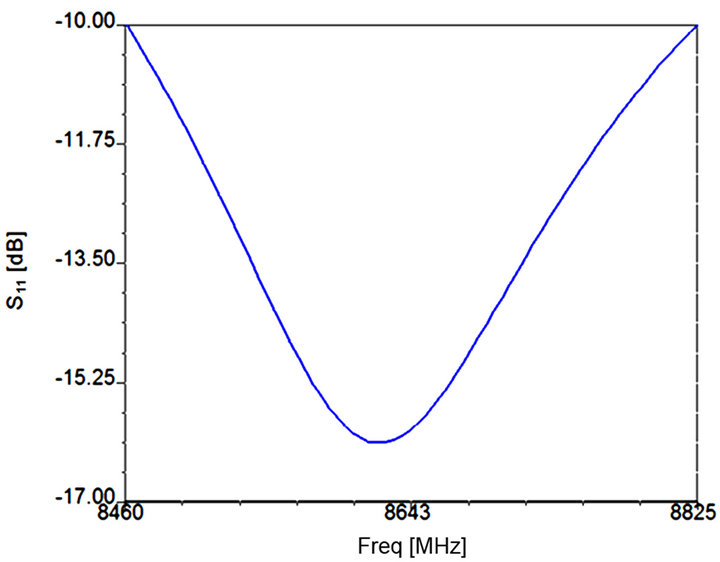
Figure 14. S11 (frequency) in B8 band.

Figure 15. 2D radiation pattern in B1 band.

Figure 16. 2D radiation pattern in B2 band.

Figure 17. 2D radiation pattern in B3 band.

Figure 18. 2D radiation pattern in B4 band.

Figure 19. 2D radiation pattern in B5 band.
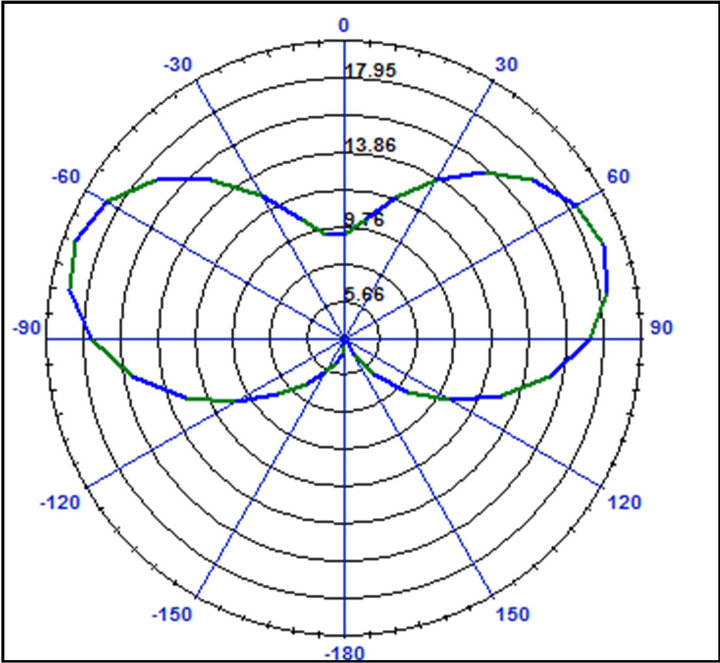
Figure 20. 2D radiation pattern in B6 band.

Figure 21. 2D radiation pattern in B7 band.

Figure 22. 2D radiation pattern in B8 band.

Figure 23. The parasitic element (in red).

Figure 24. The PCS bandwidth enhancement result.
development of antennas for the 4G and eventually the next generation (5G) will continue. The design of such antennas will depend also on the reached goal to use for 4G the same licensed frequency bands around the world.
REFERENCES
- Wikipedia Encyclopedia, “4G,” 2013. http://en.wikipedia.org/wiki/4G#United_States
- W.-J. Liao, S.-H. Chang and L.-K. Li, “A Compact Planar Multiband Antenna for Integrated Mobile Devices,” Progress in Electromagnetics Research, Vol. 109, 2010, pp. 1-16. doi:10.2528/PIER10083001
- W.-S. Chen and J.-W. Wang, “A Coupled Fed PIFA Antenna for 4G Mobile Phone Application,” 2011 IEEE International Workshop on Electromagnetics, Applications and Student Innovation, Taipei, 8-10 August 2011, pp. 1-5.
- Y.-S. Tseng, Y.-H. Tseng and W.-H. Tu, “Wideband Internal Antenna for Tablet/Laptop Applications,” 2012 Asia-Pacific Microwave conference Proceedings, Kaohsiung, 2012, pp. 310-312.
- A. N. Kulkarni and S. K. Sharman, “A Compact Multiband Antenna with MIMO Implementation for USB Size 4G LTE Wireless Devices,” Proceedings of the IEEE APSURSI, Spokane, 3-8 July 2011, pp. 2215-2218. doi:10.1109/APS.2011.5996955
- V.-A. Nguyen and S.-O. Park, “Compact Tunable-PIFA Antenna for Multiband Slim Handsets,” Proceedings of the IEEE iWAT, Chiba, 4-6 March 2008, pp. 362-365. doi:10.1109/IWAT.2008.4511355
- V.-A. Nguyen, R.-A. Bhatti and S.-O. Park, “A Simple PIFA-Based Tunable Internal Antenna for Personal Communication Handsets,” IEEE AWPS, Vol. 7, 2008, pp. 130-133. doi:10.1109/APS.2011.5996875
- R. H. Bhuiyan and M. Ali, “A Double Meander PIFA with a Parasitic Metal Box for Wideband 4G Mobile Phones,” Proceedings of the IEEE APSURSI, Spokane, 3-8 July 2011, pp. 1914-1917. doi:10.1109/APS.2011.5996875
- C. Rowell and E. Y. Lam, “Multiple Frequency Band and High Isolation Mobile Device Antennas Using a Capacitive Slot,” IEEE Transactions on Antennas and Propagation, Vol. 60, No. 8, 2012, pp. 3576-3582. doi:10.1109/TAP.2012.2201077
- C. Rowell and E. Y. Lam ”Mobile Phone Antenna Design,” IEEE Antennas and Propagation Magazine, Vol. 54, No. 4, 2012 pp. 14-34. doi:10.1109/MAP.2012.6309152
- M. A. Soliman, T. E. Taha, W. E. Swelam and A. M. Gomaa, “A Wearable Dual-Band Dielectric Patch Antenna for LTE and WLAN,” Journal of Electromagnetic Analysis and Applications, Vol. 4, No. 4, 2012 pp. 305-309.
- K. L. Virga and Y. Rahmat-Samii, “Low-Profile Enhanced Band with PIFA for Wireless Communications Packaging,” IEEE Transactions on Microwave Theory and Techniques, Vol. 45, No. 10, 1997, pp. 1879-1888. doi:10.1109/22.641786