Engineering
Vol.5 No.6(2013), Article ID:33264,6 pages DOI:10.4236/eng.2013.56064
Finite Element Modeling of Shop Built Spherical Pressure Vessels
Department of Mechanical Engineering, University of Ibadan, Ibadan, Nigeria
Email: oluwoleo2@asme.org
Copyright © 2013 Oludele Adeyefa, Oluleke Oluwole. This is an open access article distributed under the Creative Commons Attribution License, which permits unrestricted use, distribution, and reproduction in any medium, provided the original work is properly cited.
Received January 29, 2013; revised March 1, 2013; accepted March 9, 2013
Keywords: FE Modeling; Von-Mises Stresses; LNG-Spherical Vessel; Area Coordinates
ABSTRACT
This work builds on an earlier work done which used global coordinates where a large number of elements were needed to form a convergence of results for shop built spherical pressure vessels. In this work area coordinates were used. Any action that leads to an inability on the part of a structure to function as intended is known as failure. This research, therefore, investigates stresses developed in a shop built carbon steel spherical storage vessels using finite element approach as the analytical tool. 3-D finite element modeling using 3-node shallow triangular element with five degrees of freedom at each node is employed. These five degrees of freedom are the essential nodal degrees of freedom without the sixth in-plane rotation. The resulting equations from finite element analysis are coded using FORTRAN 90 computer programme. Spherical storage vessels are subjected to various internal loading pressures while nodal displacements, strains and the corresponding maximum Von-mises stresses are determined. The calculated maximum Vonmises stresses are compared with the yield strength of the shell plate material. Using specified safety factor, safety internal pressures with the corresponding shell thicknesses for shop built spherical pressure vessels are determined. The finite element modeling carried out in this research can be used to predict in-service stresses, strains, and deformations of shop built spherical pressure vessels using Von-mises yield stress as the failure criteria. The results obtained were validated by analytical method and it showed there was no significant difference (P > 0.05) with values obtained through analytical method.
1. Introduction
Considerable attention has been given to applying the finite element method in the analysis of curved structures. [1] developed conical segments for the analysis of shell of revolution. [2] modified the method and used meridional elements which were found to lead to considerably improved results for the stresses. Curved rectangular and cylindrical shell elements were also developed [3-5]. Applications have been in the area of membrane, thermal and pressure analysis [6-11].
However, to model a shell of spherical shape using the finite element method triangular and rectangular spherical shell elements are needed. [12] used curved shallow triangular element in curvilinear coordinates system to model spherical storage pressure vessels. The assumed polynomial function for the bending behaviour in their model is in term of x and y without the term x2y while the function for membrane behaviour is linear. The 3- node shallow triangular element has five degrees of freedom at each node without the in-plane rotation.
This approach gives considerable and acceptable results but at the expense of many elements leading to higher storage and computational efforts. It is observed that exclusion of tenth term in the polynomial function for the assumed polynomial represent deformation pattern for the bending of shell element accounted for the requirement for more elements. Meanwhile, to analyse the plate bending behaviour using triangular elements, in [13] classified such element as non-conforming element due to the incomplete polynomial terms in representing bending deformation pattern. [13] proposed polynomial function for the bending behaviour to be represented using area coordinated. It is said of this element derived in [13] that it passes all the patch tests and performs excellently. Indeed if the quadrature is carried out in a “reduced manner” using three quadrature points, then the element is one of the best triangles with 9 degrees of freedom that is currently available in [13]. This approach is being employed in this work for the FE modelling of spherical shell. The membrane deformation of shallow triangular shell element is represented with polynomial linear function using area coordinates. The bending deformation is assumed as it is given by in [13] for plate bending using 9 degree of freedom using area coordinates for non-conforming elements.
2. Finite Element Methodology
A detailed study of stress analysis of shop built spherical pressure vessel subjected to different internal and external pressures is carried out with the help of finite element method, which is perhaps the best currently known method available for the stress analysis of pressure vessel problems.
2.1. Displacement Field Requirements
The assumed displacement method was employed in this work to develop a shallow triangular spherical shell element without an in-plane rotation as a sixth degree of freedom. A shallow shell formulation was used to obtain the displacement fields. The element (Figure 1) has five degrees of freedom at each of the three corners [12]. Therefore, there are fifteen degrees of freedom per element. However, the assumed deformation pattern for bending of the shallow triangular shell element was according to the one given by Zienkiewicz et al. [13] in area coordinates while the deformation for the membrane is represented by linear polynomial using area coordinates as opposed to an earlier work that used global coordinates [12].
2.2. Basic Assumptions of the Analysis
The spherical shallow shell under investigation is assumed to have the following properties and to be loaded in the following manner:
• The spherical shell is taken as thin shell.
• The loads to be considered are internal pressure and external pressure.
• The displacements of the vessel are assumed to be so small that the equilibrium conditions for an element in the spherical shell is the same before and after deformation.
2.3. Displacement Functions
The assumed displacement relationships for the proposed triangular shallow shell are expressed in curvilinear coordinates in area coordinates. The use of so-called “area coordinates” is made to represent the transverse displacement, w, as a polynomial function of degree 3 as it was given by [13]. Linear polynomial equations are then used to represent the membrane displacements u and v using area coordinates, resulting in a constant strain triangle for the membrane action. The assumed displacement equations are:
 (1)
(1)
 (2)
(2)
 (3)
(3)
 (4)
(4)
 (5)
(5)
where
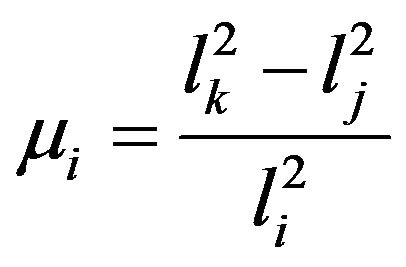
and  is the length of the side opposite node i. The modified interpolation for displacement is taken as
 (6)
(6)
to determine constants as, known displacements at nodes are substituted and the equations become
 (7)
(7)
where [δ] is the nodal degrees of freedom, [C–1] is inverse of transformation matrix and [a] is vector of independent constants.
2.4. Strain-Displacement Equations
Strain-displacement relationships for shallow thin shells as given by [14] are simplified for the shallow shell and expressed as follows in curvilinear coor-
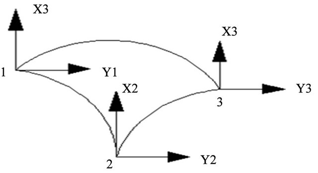
Figure 1. Shallow triangular element.
dinates.
 (8)
(8)
The above strain Equation (8) which can be written in matrix form after necessary substitutions of u, v and w given in Equations (1)-(3) into the above strain equations.
2.5. Stress in a Curved Triangular Element
Stress varies from point to point along the shell profile and also through the thickness of the shell. It is thus in reality an unknown function of two variables, therefore leads us to the equations below as it were given by [15]:
 (9)
(9)
where: M is the moment per unit length, M and  is the bending stress at the surface.
N is to be force per unit length and  which is membrane stress.
2.6. Strain Energy
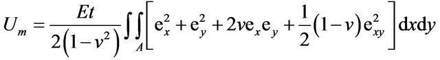
The strain energy equation for an isotropic linear shell is
 (10)
(10)
where, t = thickness of the shell, v = Poisson’s ratio and E = Modulus of elasticity.
After substitution for strains in the above expression and integration with respect to, the strain energy can be separated into the membrane energy Um and the bending energy Ub.
 (11)
(11)
 (12)
(12)
 (13)
(13)
The potential energy is then written as:  where W represents the work done by the external load on the system. In the finite element method, the potential energy of a shell is expressed as:
 (14)
(14)
where  is the potential energy of the kth element.
2.7. Stiffness Matrix
The stiffness matrix of the elements is derived from the principle of minimum potential energy, using the theory of shallow shells, which is more accurate enough for the shallow curved triangular elements considered. By writing strain energy equations in terms of area coordinates, element stiffness matrix can be determined in the usual manner,
 (15)
(15)
 (16)
(16)
km and kb are element stiffness matrices due to membrane and bending stresses respectively.
Dm and Db are elasticity matrices for membrane and bending stresses respectively.
Bm and Bb are strain matrices for membrane and bending stresses respectively.
Therefore, element total stiffness matrix is
 (17)
(17)
Element stiffness matrix is then combined to give system stiffness matrix. It is to note that stiffness matrices kb and km are in terms of area coordinates which can be integrated explicitly or in a reduced “manner” using three Gauss quadrature points. To integrate explicitly, the integral equation below as it is in [13] is very useful.
 (18)
(18)
where ![]() is the area of triangular element.
is the area of triangular element.
2.8. Consistent Load Vector
It is well known fact that the best and accurate approach for dealing with distributed loads in FEM is the use of a consistent load vector which is derived by equating the work done by the distributed load through the displacement of the element to the work done by the nodal generalized loads through the nodal displacements. If a shallow triangular shell element is acted upon by a distributed load q per unit area in the direction of w, the work done by this load is given by:
 (19)
(19)
If w is taken to be represented by:
 (20)
(20)
where [P] for the present element is given as
 (21)
(21)
where


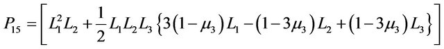
and  is as defined in Section 2.2.
The work done by the consistent nodal generalized force through the nodal displacements {δ} is given by:
 (22)
(22)
Hence, from Equations (19)-(22), the nodal forces are obtained
 (23)
(23)
Equation (23) gives the nodal forces for a single element; and the nodal forces for the whole structure are obtained by assembling the elements’ nodal forces.
2.9. Boundary Conditions
Before the system equations are ready for solution, they must be modified to account for the boundary conditions of the problem. At this junction, there is a need to give known displacement. For this system, it is assumed that displacements in all directions with the exception of radial direction are known to be zero. Also, symmetry nature of the system is taking into consideration by using 1/6th of the spherical vessel and thereby reducing the computing time. Shown in Figure 2 is a sample of the mesh with 4 elements and 6 nodes. Using area coordinates, the need for different sector angles was eliminated as was the case in [12].
3. Problem Considered
3.1. Case One
Maximum equivalent Von-Mises stresses and factor of safety determined for a spherical vessel with the material properties and simulation conditions:
Shell material specified minimum yield stress = 240 Mpa;
Shell material allowable stress = 128 Mpa;
Shell material = A516M Grade 65;
Shell material density = 7850 kg/m3;
Spherical vessel radius = 1.0 m;
Internal pressure = 10,000 N/m2;
Factor of safety based on allowable stress = 1.875.
3.2. Case Two
Maximum equivalent Von-Mises stresses and factor of safety determined for a spherical vessel with the material properties and simulation conditions:
Shell material specified minimum yield stress = 240 Mpa;
Shell material allowable stress = 128 Mpa;
Shell material = A516 M Grade 65;
Shell material density = 7850 kg/m3;
Spherical vessel radius = 1.0 m;
Internal pressure = 20,000 N/m2;
Factor of safety based on allowable stress = 1.875.
3.3. Case Three
Maximum equivalent Von-Mises stresses and factor of safety determined for a spherical vessel with the material properties and simulation conditions:
Shell material specified minimum yield stress = 240 Mpa;
Shell material allowable stress = 128 Mpa;
Shell material = A516 M Grade 65;
Shell material density = 7850 kg/m3;
Spherical vessel radius = 0.5 m;
Internal pressure = 30,000 N/m2;
Factor of safety based on allowable stress = 1.875.
4. Results and Discussions
By examining Tables 1-3, element thicknesses given
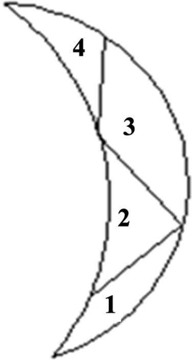
Figure 2. Typical spherical shell mesh.
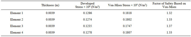
Table 1. Corresponding equivalent maximum Von-Mises stress, thickness and factor of safety internal pressure of 10.0 MPa.
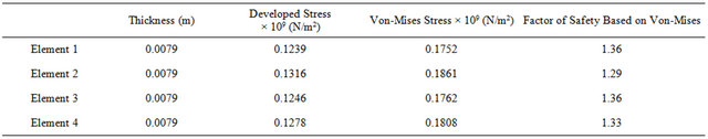
Table 2. Corresponding equivalent maximum Von-Mises stress, thickness and factor of safety internal pressure of 20.0 MPa.
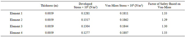
Table 3. Corresponding equivalent maximum Von-Mises stress, thickness and factor of safety internal pressure of 30.0 MPa.
in each case are uniform. This is expected because; the spherical pressure vessels in each of the cases considered was subjected to uniform internal pressure. Also, developed and Von-mises stresses calculated in each of the cases are well below the material allowable stress values as it is given by ASME sec VIII, Part D. This can be deduced from the values of factor of safety in the above tables Tables 1-3.
The thicknesses calculated are the minimum thicknesses required by the spherical shell to withstand the internal pressure. It is required of the design engineer to have the overall idea of all the possible loads/forces to act on the spherical pressure vessels. And also, the overall effects of the combination of various loads/forces.
In some cases, it is advisable to add corrosion allowance to the minimum calculated thickness. The value of corrosion allowance depends on many factors. Some of the factors are:
• The corrosion rate of the stored gas/fluid on the shell material.
• Design life of the spherical pressure vessel.
• External corrosion agents at the site.
• Corrosion control and prevention methods adopted.
Having put all these into consideration by the design engineer, minimum shell thickness due to various loads/ forces can then be determined. It is of notes that if this shell thickness is lower than the minimum shell thickness recommended by ASME code, minimum shell thickness recommended by ASME code has to be used.
REFERENCES
- P. E. Grafton and D. R. Strome, “Analysis of Axis-Symmetric Shells by the Direct Stiffness Method,” AIAA Journal, Vol. 1, No. 10, 1963, pp. 2342-2347. doi:10.2514/3.2064
- R. E. Jones and D. R. Strome, “Direct Stiffness Method Analysis of Shells of Revolution Utilizing Curved Elements,” AIAA Journal, Vol. 4, No. 9, 1966, pp. 1519- 1525. doi:10.2514/3.3729
- C. Brebbia and J. J. Connor, “Stiffness Matrix for Shallow Rectangular Shell Element,” Journal of the Engineering Mechanics Division, Vol. 93, No. 5, 1967, pp. 43- 65.
- G. Cantin and R. W. Clough, “A Curved Cylindrical Shell Finite Element,” AIAA Journal, Vol. 6, No. 6, 1968, pp. 1057-1062. doi:10.2514/3.4673
- A. B. Sabir and A. C. Lock, “A Curved Cylindrical Shell Finite Element,” International Journal Mechanical Science, Vol. 14, No. 2, 1972, pp. 125-135. doi:10.1016/0020-7403(72)90093-8
- Christchurch Convention Centre, Christchurch, 2006. http://www.contech.co.nz/uploaded/Post-tensioned%20LNG%20Storage%20Tanks.pdf
- Q. S. Chen, J. Wegrezyn and V. Prasad, “Analysis of Temperature and Pressure Changes in Liquefied Natural Gas (LNG) Cryogenic Tanks,” Cryogenics, Vol. 44, No. 10, 2004, pp. 701-709. doi:10.1016/j.cryogenics.2004.03.020
- S. J. Jeon, B.-M. Jin and Y.-J. Kim, “Consistent Thermal Analysis Procedure of LNG Storage Tank,” Structural Engineering and Mechanics, Vol. 25, No. 4, 2007, pp. 445-466.
- B. T. Oh, S. H. Hong, Y. M. Yang, I. S. Yoon and Y. K. Kim, “The Development of KOGAS Membrane for LNG Storage Tank,” Proceedings of the 13th International Offshore and Polar Engineering Conference, Honolulu, May 25-30 2003, pp. 441-446.
- M. Graczyk, T. Moan and O. Rognebakke, “Probabilistic Analysis of Characteristic Pressure for LNG Tank,” Journal of Offshore Mechanics and Arctic Engineering, Vol. 128, No. 2, 2005, pp. 128-133.
- S. R. Gorlar and O. Haddad, “Finite Element Heat Transfer and Structural Analysis of a Cone-Cylinder Pressure Vessel,” International Journal of Applied Mechanics and Engineering, Vol. 12, 2007, pp. 951-963.
- O. Adeyefa and O. Oluwole, “Finite Element Analysis of Von-Mises Stress Distribution in a Spherical Shell of Liquefied Natural Gas (LNG) Pressure Vessels,” Engineering, Vol. 3, 2011, pp. 1012-1017. doi:10.4236/eng.2011.310125
- O. C. Zienkiewicz and R. L. Taylor, “The Finite Element Method,” 5th Edition, Vol. 2, Solid Mechanics, Butterworth-Heinemann, Oxford, 2000.
- E. Reissner, “On Some Problems in Shell Theory, Proceedings of the 1st Symposium on Naval Structural Mechanics,” Stanford University, Pergaman Press Inc., New York, 1958.
- W. H. Bowes and L. T. Russell, “Stress Analysis by the Finite Element Method for Practicing Engineers,” Lexington Books, Lexington, 1975.